Brake warning lamp JEEP XJ 1995 Service And User Guide
[x] Cancel search | Manufacturer: JEEP, Model Year: 1995, Model line: XJ, Model: JEEP XJ 1995Pages: 2158, PDF Size: 81.9 MB
Page 388 of 2158
INDICATOR LAMPS
If an individual indicator lamp is inoperative, see
the diagnostic procedure under the heading for that
lamp. If more than one indicator lamp or a combina-
tion of lamps and gauges in the main cluster or the
gauge package cluster is inoperative, see Gauges in
this section for diagnosis.
ANTI-LOCK BRAKE SYSTEM LAMP
The diagnosis found here addresses an inoperative
lamp condition. If the ABS lamp stays on with the ig-
nition switch in the ON position, or comes on and
stays on while driving, refer to Group 5 - Brakes for
diagnosis. If no ABS problem is found, the following
procedure will help locate a short or open in the ABS
lamp circuit.
(1) Disconnect battery negative cable. Remove left
instrument cluster bezel and main cluster assembly.
Disconnect ABS control module connector.
(2) Install a jumper wire between cavity 6 of clus-
ter connector and a good ground. Connect battery
negative cable. Turn ignition switch to ON. Lamp
should light. If OK, remove jumper wire and go to
next step. If not OK, replace bulb.
(3) Turn ignition switch to OFF. Disconnect battery
negative cable and unplug cluster connector. Check
for continuity between cavity 6 of cluster connector
and a good ground. There should be no continuity. If
OK, go to next step. If not OK, repair short circuit as
required.
(4) Check continuity between cavity 6 of cluster
connector and cavity 52 of ABS control module con-
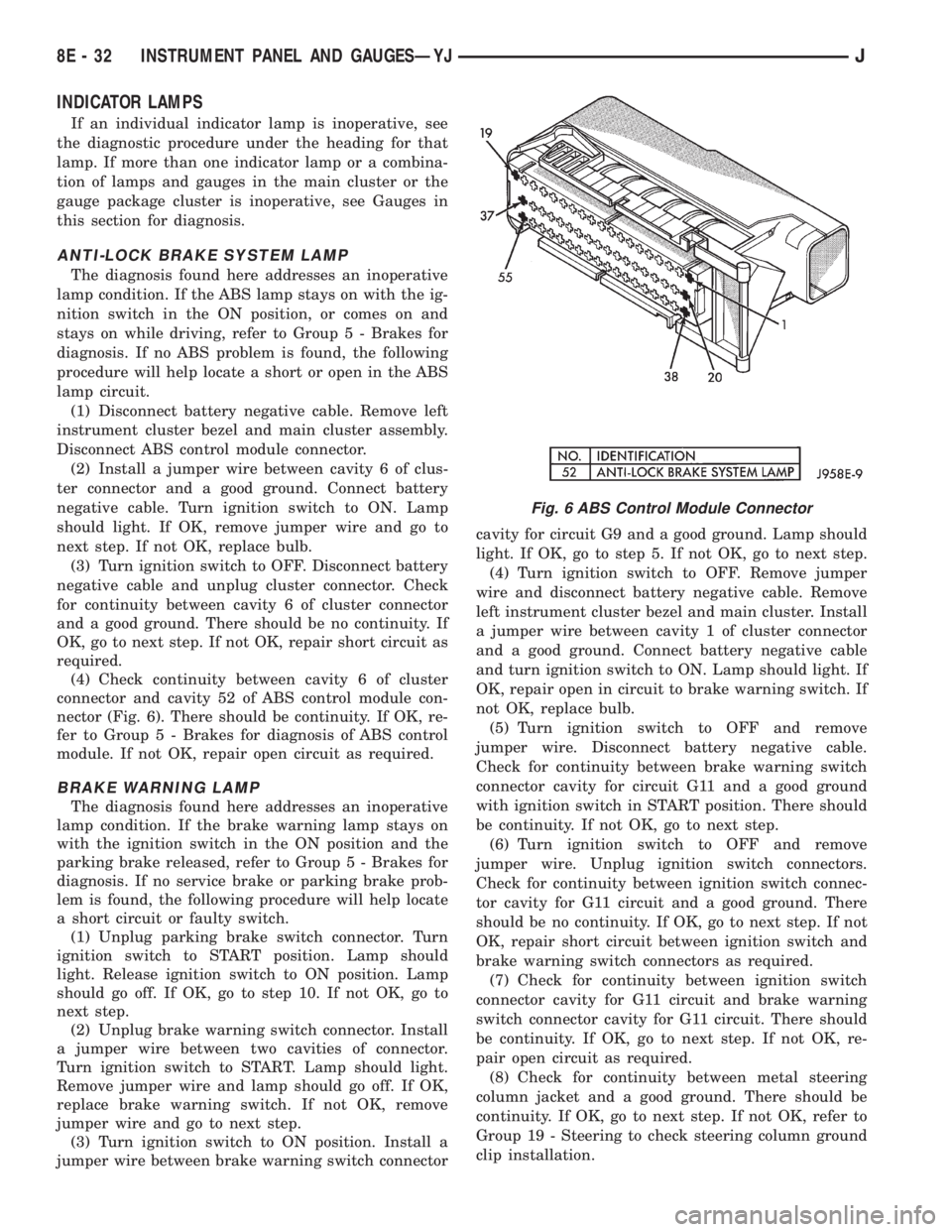
nector (Fig. 6). There should be continuity. If OK, re-
fer to Group 5 - Brakes for diagnosis of ABS control
module. If not OK, repair open circuit as required.
BRAKE WARNING LAMP
The diagnosis found here addresses an inoperative
lamp condition. If the brake warning lamp stays on
with the ignition switch in the ON position and the
parking brake released, refer to Group 5 - Brakes for
diagnosis. If no service brake or parking brake prob-
lem is found, the following procedure will help locate
a short circuit or faulty switch.
(1) Unplug parking brake switch connector. Turn
ignition switch to START position. Lamp should
light. Release ignition switch to ON position. Lamp
should go off. If OK, go to step 10. If not OK, go to
next step.
(2) Unplug brake warning switch connector. Install
a jumper wire between two cavities of connector.
Turn ignition switch to START. Lamp should light.
Remove jumper wire and lamp should go off. If OK,
replace brake warning switch. If not OK, remove
jumper wire and go to next step.
(3) Turn ignition switch to ON position. Install a
jumper wire between brake warning switch connectorcavity for circuit G9 and a good ground. Lamp should
light. If OK, go to step 5. If not OK, go to next step.
(4) Turn ignition switch to OFF. Remove jumper
wire and disconnect battery negative cable. Remove
left instrument cluster bezel and main cluster. Install
a jumper wire between cavity 1 of cluster connector
and a good ground. Connect battery negative cable
and turn ignition switch to ON. Lamp should light. If
OK, repair open in circuit to brake warning switch. If
not OK, replace bulb.
(5) Turn ignition switch to OFF and remove
jumper wire. Disconnect battery negative cable.
Check for continuity between brake warning switch
connector cavity for circuit G11 and a good ground
with ignition switch in START position. There should
be continuity. If not OK, go to next step.
(6) Turn ignition switch to OFF and remove
jumper wire. Unplug ignition switch connectors.
Check for continuity between ignition switch connec-
tor cavity for G11 circuit and a good ground. There
should be no continuity. If OK, go to next step. If not
OK, repair short circuit between ignition switch and
brake warning switch connectors as required.
(7) Check for continuity between ignition switch
connector cavity for G11 circuit and brake warning
switch connector cavity for G11 circuit. There should
be continuity. If OK, go to next step. If not OK, re-
pair open circuit as required.
(8) Check for continuity between metal steering
column jacket and a good ground. There should be
continuity. If OK, go to next step. If not OK, refer to
Group 19 - Steering to check steering column ground
clip installation.
Fig. 6 ABS Control Module Connector
8E - 32 INSTRUMENT PANEL AND GAUGESÐYJJ
Page 389 of 2158
(9) Turn ignition switch to START position and
hold there. Check for continuity between terminal for
circuit G11 of ignition switch and a good ground.
There should be continuity. If not OK, replace igni-
tion switch.
(10) Unplug brake warning switch connector.
Check for continuity between parking brake switch
connector and a good ground. There should be no
continuity. If OK, go to next step. If not OK, repair
short circuit as required.
(11) Check for continuity between parking brake
switch connector and brake warning switch connector
cavity for circuit G11. There should be continuity. If
OK, replace parking brake switch. If not OK, repair
open circuit to brake warning switch as required.
FOUR-WHEEL DRIVE INDICATOR LAMP
(1) Apply parking brake, start engine, vehicle in
4WD Lock or 4WD.
(2) Unplug switch and touch harness side of wire
to ground. Lamp should light. If OK, check switch
operation, replace if bad. If bulb is OK, repair open
to indicator.
HEADLAMP HIGH BEAM INDICATOR LAMP
(1) Check that headlamp high beams are func-
tional. If OK, go to next step. If not OK, refer to
Group 8L - Lamps for diagnosis of headlamp system.
(2) Disconnect battery negative cable. Remove left
instrument cluster bezel and main cluster assembly.
Unplug cluster connector. Connect battery negative
cable. Turn headlamps on and select high beam.
Check for battery voltage at cavity 17 of cluster con-
nector. If OK, replace indicator bulb. If not OK, re-
pair circuit to headlamp dimmer switch as required.
MALFUNCTION INDICATOR LAMP
The diagnosis found here addresses an inoperative
lamp condition. If the lamp comes on and stays on
with engine running, refer to Group 14 - Fuel System
for diagnosis. If no fuel or emission system problem
is found, the following procedure will help locate a
short or open in the lamp circuit.
(1) Disconnect battery negative cable. Unplug PCM
connector. Install a jumper wire from cavity 32 of
PCM connector (Fig. 5) to a good ground. Connect
battery negative cable. Turn ignition switch to ON.
Lamp should light. Remove jumper wire and lamp
should go OFF. If OK, refer to Powertrain Diagnostic
Procedures to check PCM. If not OK, go to next step.
(2) Turn ignition switch to OFF. Disconnect battery
negative cable. Remove left instrument cluster bezel
and main cluster assembly. Install a jumper wire
from cavity 2 of cluster connector to a good ground.
Connect battery negative cable. Turn ignition switch
to ON. Lamp should light. If OK, go to next step. If
not OK, replace bulb.(3) Turn ignition switch to OFF. Disconnect battery
negative cable. Unplug cluster connector. Check for
continuity between cavity 2 of cluster connector and
a good ground. There should be no continuity. If OK,
go to next step. If not OK, repair short circuit to
PCM as required.
(4) Check continuity between cavity 2 of cluster
connector and cavity 32 of PCM connector. There
should be continuity. If not OK, repair open circuit to
PCM as required.
SEAT BELT REMINDER LAMP
(1) Refer to Group 8U - Chime/Buzzer Warning
Systems to check chime/buzzer module operation. If
OK, go to next step. If not OK, replace chime/buzzer
module.
(2) Disconnect battery negative cable. Remove left
instrument cluster bezel and main cluster assembly.
Unplug cluster connector. Check for continuity be-
tween cavity 20 of cluster connector and a good
ground. There should be continuity. If OK, plug clus-
ter connector back into cluster and go to next step. If
not OK, repair open circuit to ground as required.
(3) Connect battery negative cable. Install a
jumper wire between a 12-volt battery feed and cav-
ity 16 of cluster connector. Lamp should light. If OK,
go to next step. If not OK, replace bulb.
(4) Disconnect battery negative cable. Unplug
chime/buzzer module from fuseblock module. Unplug
cluster connector. Check for continuity between cav-
ity 16 of cluster connector and a good ground. There
should be no continuity. If OK, go to next step. If not
OK, repair short circuit to chime/buzzer module as
required.
(5) Check continuity between cavity 16 of cluster
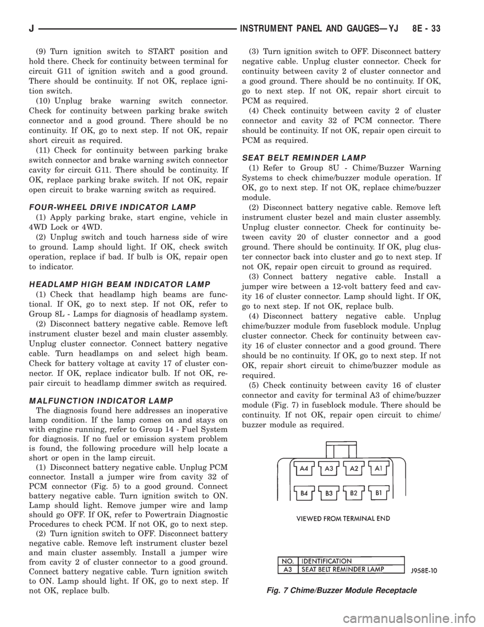
connector and cavity for terminal A3 of chime/buzzer
module (Fig. 7) in fuseblock module. There should be
continuity. If not OK, repair open circuit to chime/
buzzer module as required.
Fig. 7 Chime/Buzzer Module Receptacle
JINSTRUMENT PANEL AND GAUGESÐYJ 8E - 33
Page 422 of 2158
SPEED CONTROL SWITCH
WARNING: ON VEHICLES EQUIPPED WITH AN AIR-
BAG, REFER TO GROUP 8M - RESTRAINT SYS-
TEMS BEFORE ATTEMPTING STEERING WHEEL
COMPONENT DIAGNOSIS OR SERVICE. FAILURE
TO TAKE PROPER PRECAUTIONS COULD RESULT
IN ACCIDENTAL AIRBAG DEPLOYMENT AND POS-
SIBLE PERSONAL INJURY.
(1) Disconnect battery negative cable. Remove
speed control switch from steering wheel.
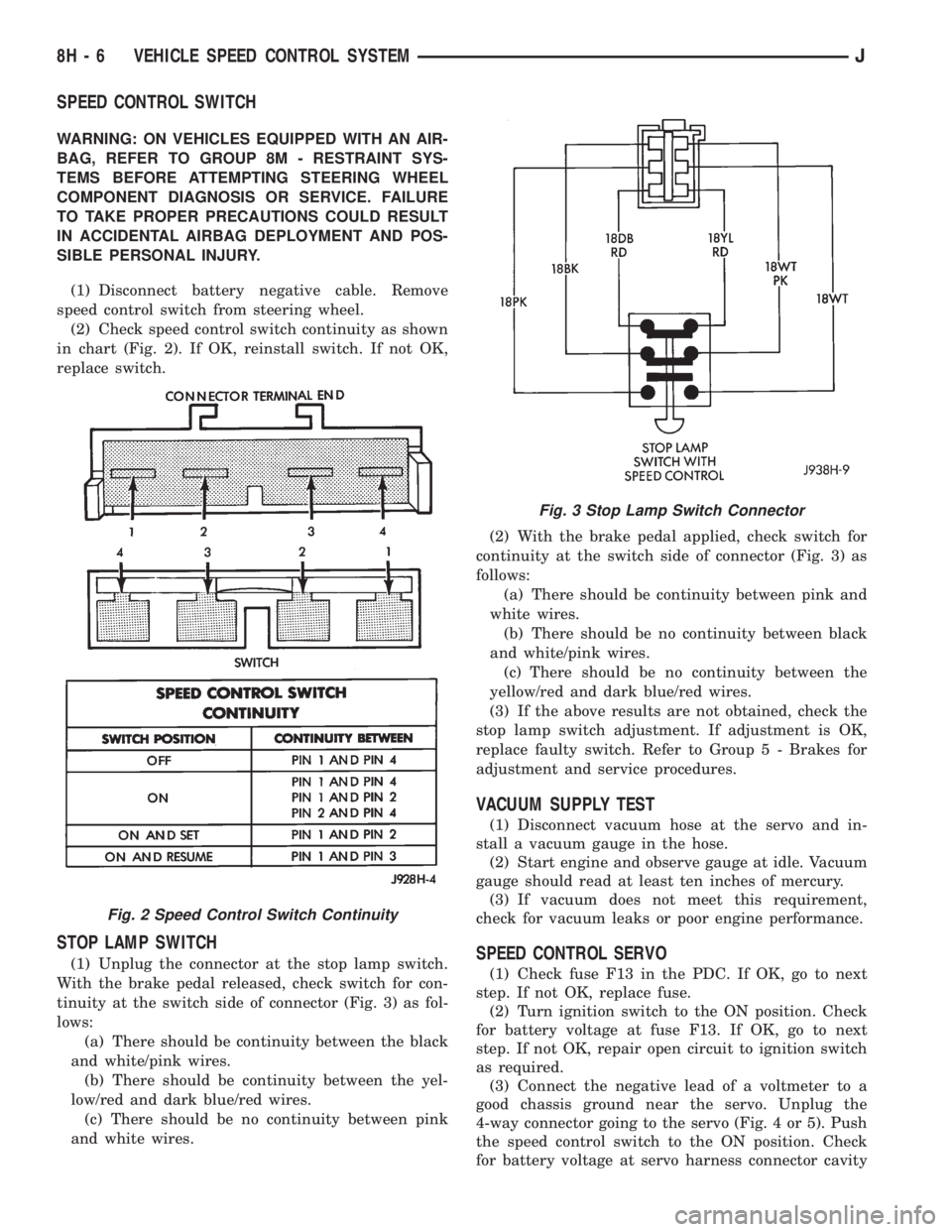
(2) Check speed control switch continuity as shown
in chart (Fig. 2). If OK, reinstall switch. If not OK,
replace switch.
STOP LAMP SWITCH
(1) Unplug the connector at the stop lamp switch.
With the brake pedal released, check switch for con-
tinuity at the switch side of connector (Fig. 3) as fol-
lows:
(a) There should be continuity between the black
and white/pink wires.
(b) There should be continuity between the yel-
low/red and dark blue/red wires.
(c) There should be no continuity between pink
and white wires.(2) With the brake pedal applied, check switch for
continuity at the switch side of connector (Fig. 3) as
follows:
(a) There should be continuity between pink and
white wires.
(b) There should be no continuity between black
and white/pink wires.
(c) There should be no continuity between the
yellow/red and dark blue/red wires.
(3) If the above results are not obtained, check the
stop lamp switch adjustment. If adjustment is OK,
replace faulty switch. Refer to Group 5 - Brakes for
adjustment and service procedures.
VACUUM SUPPLY TEST
(1) Disconnect vacuum hose at the servo and in-
stall a vacuum gauge in the hose.
(2) Start engine and observe gauge at idle. Vacuum
gauge should read at least ten inches of mercury.
(3) If vacuum does not meet this requirement,
check for vacuum leaks or poor engine performance.
SPEED CONTROL SERVO
(1) Check fuse F13 in the PDC. If OK, go to next
step. If not OK, replace fuse.
(2) Turn ignition switch to the ON position. Check
for battery voltage at fuse F13. If OK, go to next
step. If not OK, repair open circuit to ignition switch
as required.
(3) Connect the negative lead of a voltmeter to a
good chassis ground near the servo. Unplug the
4-way connector going to the servo (Fig. 4 or 5). Push
the speed control switch to the ON position. Check
for battery voltage at servo harness connector cavity
Fig. 2 Speed Control Switch Continuity
Fig. 3 Stop Lamp Switch Connector
8H - 6 VEHICLE SPEED CONTROL SYSTEMJ
Page 478 of 2158
BULB APPLICATIONÐXJ VEHICLES
GENERAL INFORMATION
The following Bulb Application Table lists the lamp
title on the left side of the column and trade number
or part number on the right.
CAUTION: Do not use bulbs that have a higher can-
dle power than the bulb listed in the Bulb Applica-
tion Table. Damage to lamp can result.
Do not touch halogen bulbs with fingers or other
oily surfaces. Bulb life will be reduced.
EXTERIOR LAMPSÐXJ
Back-up .................................................................1156
Center High Mounted Stoplamp ..........................922
Fog ............................................................................H3
Front Side Marker .................................................194
Headlamp/Sealed Beam....................................H6054
License Plate ..........................................................168
License Plate W/Outside Spare ..............................67
Park/Turn Signal ............................................2057NA
Tail/Stop ................................................................2057
Turn Signal ...........................................................1156
INTERIOR LAMPSÐXJ
Service procedures for most of the lamps in the in-
strument panel, Instrument cluster and switches are
located in Group 8E, Instrument Panel and Gauges.
Some components have lamps that can only be ser-
viced by an Authorized Service Center (ASC) after
the component is removed from the vehicle. Contact
local dealer for location of nearest ASC.
Cargo .......................................................................561
Dome .......................................................................561
Dome/Reading.........................................................906Glove Compartment ...............................................194
Overhead Console ..................................................912
Under Hood ............................................................105
Vanity Mirror ...........................................................74
Underpanel Courtesy.............................................168
INDICATOR LAMPS
Service procedures for most of the lamps in the in-
strument panel, instrument cluster and switches are
located in Group 8E, Instrument Panel and Gauges.
A/C Control ...............................................................74
Airbag ........................................................................74
Anti-lock Brake ........................................................74
Ash Receiver .........................................................1891
Brake Warning .........................................................74
Check Engine ...........................................................74
Cigar Lighter ............................................................53
Diesel Wait ...............................................................74
Fasten Seat Belts ....................................................74
Four Wheel Drive ....................................................74
Generator ................................................................194
Generator/Diesel.......................................................74
Heater Control .........................................................74
High Beam..............................................................194
Illumination ............................................................194
Low Fuel .................................................................194
Low Washer Fluid....................................................74
Radio ......................................................................ASC
Rocker Switch...........................................................37
Seat Belt ...................................................................74
Transfer Case .........................................................658
Transmission Floor Shift.......................................658
Turn Signal.............................................................194
Shift ...........................................................................74
Water In Fuel ...........................................................74
8L - 18 LAMPSÐXJ VEHICLESJ
Page 492 of 2158
BULB APPLICATIONÐYJ VEHICLES
GENERAL INFORMATION
The following Bulb Application Table lists the lamp
title on the left side of the column and trade number
or part number on the right.
CAUTION: Do not use bulbs that have a higher can-
dle power than the bulb listed in the Bulb Applica-
tion Table. Damage to lamp can result.
Do not touch halogen bulbs with fingers or other
oily surfaces. Bulb life will be reduced.
EXTERIOR LAMPSÐYJ
Back-up .................................................................1156
Center High Mounted Stoplamp ..........................912
Fog ............................................................................H3
Front Side Marker .................................................194
Headlamp/Sealed Beam....................................H6054
Park/Turn Signal..................................................3157
Tail/Stop ................................................................1157
INTERIOR LAMPSÐYJ
Service procedures for most of the lamps in the in-
strument panel, Instrument cluster and switches are
located in Group 8E, Instrument Panel and Gauges.
Some components have lamps that can only be ser-
viced by an Authorized Service Center (ASC) after
the component is removed from the vehicle. Contact
local dealer for location of nearest ASC.Dome/Cargo .........................................................212-2
Glove Compartment ...............................................194
Under Hood ............................................................105
Underpanel Courtesy...............................................89
INDICATOR LAMPS
Service procedures for most of the lamps in the in-
strument panel, instrument cluster and switches are
located in Group 8E, Instrument Panel and Gauges.
A/C Control ...............................................................74
Anti-lock Brake ........................................................74
Ash Receiver .........................................................1891
Brake Warning .........................................................74
Cigar Lighter ............................................................53
Fasten Seat Belts ....................................................74
Four Wheel Drive ....................................................74
Generator ................................................................194
Hazard.......................................................................74
Heater Control .......................................................194
High Beam..............................................................194
Illumination ............................................................194
Low Coolant..............................................................74
Radio ......................................................................ASC
Rocker Switch...........................................................74
Seat Belt ...................................................................74
Shift ...........................................................................74
Turn Signal.............................................................194
8L - 32 LAMPSÐYJ VEHICLESJ
Page 543 of 2158
WIRING DIAGRAMS
CONTENTS
page page
8W-01 GENERAL INFORMATIONÐWIRING
DIAGRAMS.................... 8W-01-1
8W-10 FUSE/FUSE BLOCK........... 8W-10-1
8W-11 POWER DISTRIBUTION........ 8W-11-1
8W-15 GROUND DISTRIBUTION....... 8W-15-1
8W-20 CHARGING SYSTEM.......... 8W-20-1
8W-21 STARTING SYSTEM........... 8W-21-1
8W-30 FUEL/IGNITION.............. 8W-30-1
8W-31 TRANSMISSION CONTROLS.... 8W-31-1
8W-32 ANTI-LOCK BRAKES.......... 8W-32-1
8W-33 VEHICLE SPEED CONTROL..... 8W-33-1
8W-40 INSTRUMENT CLUSTER....... 8W-40-1
8W-41 HORN/CIGAR LIGHTER......... 8W-41-1
8W-42 AIR CONDITIONING/HEATER.... 8W-42-1
8W-44 INTERIOR LIGHTING.......... 8W-44-1
8W-47 AUDIO SYSTEM.............. 8W-47-18W-48 HEATED REAR WINDOW....... 8W-48-1
8W-49 OVERHEAD CONSOLE......... 8W-49-1
8W-50 FRONT LIGHTING............. 8W-50-1
8W-51 REAR LIGHTING............. 8W-51-1
8W-52 TURN SIGNALS.............. 8W-52-1
8W-53 WIPERS..................... 8W-53-1
8W-54 TRAILER TOW................ 8W-54-1
8W-60 POWER WINDOWS.......... 8W-60-1
8W-61 POWER DOOR LOCKS......... 8W-61-1
8W-62 POWER MIRRORS............ 8W-62-1
8W-63 POWER SEAT................ 8W-63-1
8W-70 SPLICE INFORMATION........ 8W-70-1
8W-80 CONNECTOR PIN OUTS....... 8W-80-1
8W-90 CONNECTOR LOCATIONS...... 8W-90-1
8W-95 SPLICE LOCATIONS........... 8W-95-1
HOW TO USE THIS GROUP
The purpose of this group is to show the electrical
circuits in a clear, simple fashion and to make trou-
bleshooting easier. Components that work together
are shown together. All electrical components used in
a specific system are shown on one diagram. The feed
for a system is shown at the top of the page. All
wires, connectors, splices, and components are shown
in the flow of current to the bottom of the page. Wir-
ing which is not part of the circuit represented is ref-
erenced to another page/section, where the complete
circuit is shown. In addition, all switches, compo-
nents, and modules are shown in theat rest posi-
tion with the doors closed and the key removed
from the ignition.
If a component is part of several different circuits,
it is shown in the diagram for each. For example, the
headlamp switch is the main part of the exterior
lighting, but it also affects the interior lighting and
the chime warning system.
It is important to realize that no attempt is
made on the diagrams to represent components
and wiring as they appear on the vehicle. For
example, a short piece of wire is treated the
same as a long one. In addition, switches and
other components are shown as simply as pos-
sible, with regard to function only.
The wiring diagram show circuits for all wheel-
bases. If there is a difference in systems or compo-
nents between wheel-bases, an identifier is placed
next to the component.
SECTION IDENTIFICATION
Sections in Group 8W are organized by sub-sys-
tems. The sections contain circuit operation descrip-
tions, helpful information, and system diagrams. The
intention is to organize information by system, con-
sistently from year to year.
CONNECTOR LOCATIONS
Section 8W-90 contains Connector Location illus-
trations. The illustrations contain the connector
number and component identification. Connector Lo-
cation charts in Section 8W-90 reference the illustra-
tion number for components and connectors.
Section 8W-80 shows each connector and the cir-
cuits involved with that connector. The connectors
are identified using the number on the Diagram
pages.
SPLICE LOCATIONS
Splice Location charts in Section 8W-70 show the
entire splice, and provide references to other sections
the splice serves.
Section 8W-95 contains illustrations that show the
general location of the splices in each harness. The
illustrations show the splice by number, and provide
a written location.
JWIRING DIAGRAMSÐXJ VEHICLES 8W - 1 - 1
Page 589 of 2158
FUEL/IGNITION
INDEX
page page
Automatic Shut Down (ASD) Relay............. 1
Battery Feed.............................. 1
Brake Switch Input......................... 5
Camshaft Position Sensor.................... 3
CCDBus ................................ 5
Crankshaft Position Sensor................... 3
Data Link Connector........................ 5
Diagram Index Ð2.5L Engine.................. 6
Diagram Index Ð4.0L Engine.................. 6
Engine Coolant Temperature Sensor............ 3
Extended Idle Switch....................... 5
Fuel Injectors............................. 1
Fuel Pump Module......................... 2
Fuel Pump Relay.......................... 2
Heated Oxygen Sensor...................... 3Idle Air Control (IAC) Motor................... 2
Ignition Coil.............................. 2
Ignition Switch............................ 1
Intake Air Temperature Sensor................ 4
Malfunction Indicator Lamp (MIL)............... 5
Manifold Absolute Pressure Sensor............. 4
Park/Neutral Position Switch.................. 4
Power (Device) Ground...................... 5
Power Steering Pressure Switch............... 5
Tachometer Signal......................... 5
Throttle Position Sensor..................... 4
Torque Converter Clutch (TCC) Solenoid and
Relay................................. 4
Upshift Lamp............................. 5
Vehicle Speed Sensor....................... 2
IGNITION SWITCH
Circuit A1 from fuse 11 in the power distribution
center (PDC), supplies battery voltage to the ignition
switch. Depending upon position, the ignition switch
powers circuits A21, A38, A41, or A48.
START POSITION
In the START position, the ignition switch connects
circuit A1 to circuit A41. Circuit A41 connects to the
coil side of the starter motor relay.
Additionally in the START position, the case
grounded ignition switch provides ground for the
brake lamp switch and the warning lamps in the
instrument cluster.
START OR RUN POSITION
In the START or RUN position, the ignition switch
connects circuit A1 to circuit A21. Circuit A21 splices
to power fuse 17 in the fuse block and the coil side of
the Automatic Shut Down (ASD) relay and the fuel
pump relay.
RUN (ONLY) POSITION
When the ignition switch is in the RUN position, it
connects circuit A1 to circuit A38. Circuit A22 splices
to power fuses 1 and 7 in the fuse block.
²Fuse 1 powers the rear wiper system on circuit
V15.
²Fuse 7 feeds the Anti-Lock Brake System (ABS) on
circuit 236.
ACCESSORY OR RUN POSITIONS
In the ACCESSORY or RUN positions, the ignition
switch connects circuit A1 to circuit A48. Circuit A48
connects to a bus bar in the fuse block that feeds
fuses 2, 5, and 8.
AUTOMATIC SHUT DOWN (ASD) RELAY
When the ignition switch is in either the START or
RUN positions, it connects circuit A1 from fuse 6 in
the Power Distribution Center (PDC) to circuit A21.
Circuit A21 supplies battery voltage to the coil side of
the Automatic Shut Down (ASD) relay. The Power-
train Control Module (PCM) provides ground for the
relay on circuit K51. Circuit K51 connects to cavity 51
of the PCM.
When the PCM grounds the ASD relay, contacts
inside the relay close and connect circuit A18 from
fuse 14 in the PDC to circuit A142. Circuit A142
splices to the generator field terminal, fuel injectors,
and ignition coil. Circuit A142 also connects to cavity
57 of the PCM.
HELPFUL INFORMATION
²Along with supplying voltage to the coil side of the
ASD relay, circuit A21 also supplies voltage to the coil
side of the fuel pump relay.
BATTERY FEED
Circuit A14 from fuse 2 in the Power Distribution
Center (PDC) supplies battery voltage to cavity 3 of
the powertrain control module.
HELPFUL INFORMATION
Circuit A14 also supplies power to the contact sides
of the fuel pump relay and fuse F2 in the PDC. Fuse
F2 powers circuit A18 which supplies voltage to the
contact side of the automatic shut down relay.
FUEL INJECTORS
When the Automatic Shut Down (ASD) relay con-
tacts close, they connect circuits A14 and A142. Cir-
J8W-30 FUEL/IGNITIONÐXJ VEHICLES 8W - 30 - 1
Page 613 of 2158
ANTI-LOCK BRAKES
INDEX
page page
ABS Power Relay.......................... 1
ABS Pump Motor Relay..................... 1
ABS Warning Lamp........................ 2
Acceleration Switch......................... 1
Brake Switch Input......................... 2
Data Link Connector........................ 2Diagram Index............................ 3
General Information........................ 1
Hydraulic Control Unit....................... 2
Pump Motor Speed Sensor................... 2
Wheel Speed Sensors...................... 1
GENERAL INFORMATION
Three fuses supply power for the Anti-Lock Brake
System (ABS); fuses 8 and 10 in the Power Distribu-
tion Center (PDC) and fuse 7 in the fuse block. Fuses
8 and 10 in the PDC are connected directly to battery
voltage and are HOT all times. Fuse 7 in the fuse
block is HOT when the ignition switch is the RUN
Position.
In the RUN position, the ignition switch connects
circuit A1 from fuse 6 in the PDC with circuit A38.
Circuit A38 connects to a bus bar in the fuse block.
The bus bar feeds circuit B236 through fuse 7. Fuse 7
is a 2 amp fuse.
Circuit B236 connects to the coil side of the ABS
power relay and cavity 53 of the ABS control module.
Circuit Z1 provides ground for the ABS control mod-
ule. Circuit Z1 connects to cavities 1 and 19 of the
ABS control module.
Refer to group 5, Brakes for operational descrip-
tions of ABS system components.
WHEEL SPEED SENSORS
The all wheel anti-lock system uses four wheel
speed sensors; one for each wheel. Each sensor con-
verts wheel speed into an electrical signal that it
transmits to the ABS control module. A pair of
twisted wires connect to each sensor to provide sig-
nals to the ABS control module.
Circuits B6 and B7 provide signals to ABS control
module from right front wheel speed sensor. Circuit
B6 which provides the LOW signal connects to cavity
29 of the ABS control module. Circuit B7 connects to
cavity 47 of the module and provides the HIGH sig-
nal.
Circuits B8 and B9 provide signals to ABS control
module from left front wheel speed sensor. Circuit B8,
which provides the LOW signal, connects to cavity 30
of the ABS control module. Circuit B9 connects to
cavity 48 of the module and provides the HIGH sig-
nal.
Circuits B1 and B2 provide signals to ABS control
module from right rear wheel speed sensor. Circuit
B1 which provides the LOW signal connects to cavity45 of the ABS control module. Circuit B2 connects to
cavity 27 of the module and provides the HIGH sig-
nal.
Circuits B4 and B3 provide signals to ABS control
module from left rear wheel speed sensor. Circuit B3,
which provides the LOW signal, connects to cavity 28
of the ABS control module. Circuit B4 connects to
cavity 46 of the module and provides the HIGH sig-
nal.
ACCELERATION SWITCH
During four-wheel drive operation, the acceleration
(G) switch provides deceleration data to the ABS con-
trol module. Refer to Group 5, Brakes for additional
information.
Circuits B515, B516, and B517 connect the accel-
eration sensor to the ABS control module. Circuits
B515 and B516 provide switch states while circuit
B517 provides ground. At the ABS control module
circuit B515 connects to cavity 25, circuit B516 con-
nects to cavity 43 and circuit B517 connects to cavity
26.
ABS POWER RELAY
The ABS power relay is located in the power distri-
bution center (PDC). When the ABS module grounds
the ABS power relay on circuit B207, the relay
switches to connect circuit A20 from PDC fuse 10 to
circuit B235. Circuit B236 from fuse 7 in the fuse
block splices to feed the coil side of the ABS power
relay. Circuit B207 connects to cavity 34 of the ABS
control module.
Circuit B235 is double crimped at the ABS power
relay. One branch of circuit B235 supplies power to
the coil side of the ABS pump motor relay. The other
branch of circuit B235 splices to cavities 3 and 33 of
the ABS control module and to the hydraulic control
unit.
ABS PUMP MOTOR RELAY
The ABS pump motor relay in the power distribu-
tion center (PDC) supplies voltage to the ABS pump
motor. When the ABS power relay energizes, circuit
B235 supplies battery voltage to the coil side of the
J8W-32 ANTI-LOCK BRAKESÐXJ VEHICLES 8W - 32 - 1
Page 614 of 2158
ABS pump motor relay. The ABS control module pro-
vides ground for the relay on circuit B116. Circuit
B116 connects to cavity 15 of the ABS control mod-
ule.
When the ABS pump motor energizes, it connects
circuit A10 from PDC fuse 8 to circuit B233. Circuit
B233 supplies battery voltage to the pump motor.
Circuit Z12 provides ground for the pump motor.
PUMP MOTOR SPEED SENSOR
The input from the pump motor speed sensor tells
the ABS control module that the pump is operating.
Circuits B219 and B220 from the control module con-
nect to the speed sensor.
BRAKE SWITCH INPUT
Circuit L50 from the stop lamp provides the brake
switch input to the ABS control module. When the
brake pedal is depressed, the stop lamp switch closes
to supply battery voltage from circuit L9 to circuit
L50. Circuit L50 connects to cavity 32 of the ABS
control module. Circuit L9 originates at fuse 4 in the
Power Distribution Center (PDC).
HYDRAULIC CONTROL UNIT
When the ABS power relay energizes, two branches
of circuit B235 splice to supply voltage to the isola-
tion and dump solenoids in the hydraulic control
unit. The hydraulic control unit contains three sepa-
rate isolation solenoids and three separate dump so-
lenoids. The ABS control module activates the decay
and isolation solenoids by providing separate ground
paths for each.
The ABS module provides a ground path for the
rear isolation solenoid on circuit B251. Circuit B251
connects to cavity 54 of the ABS control module.
For the right front isolation solenoid, the ABS mod-
ule provides a ground path on circuit B249. Circuit
B249 connects to cavity 38 of the ABS control mod-
ule.
On circuit B245, the ABS module provides ground
for the left front isolation solenoid. Circuit B245 con-
nects to cavity 20 of the ABS control module.
The ABS module provides a ground path for the
rear decay solenoid on circuit B254. Circuit B254
connects to cavity 36 of the ABS control module.For the right front decay solenoid, the ABS module
provides a ground path on circuit B248. Circuit B248
connects to cavity 21 of the ABS control module.
On circuit B243, the ABS module provides ground
for the left decay solenoid. Circuit B243 connects to
cavity 2 of the ABS control module.
ABS WARNING LAMP
Circuit F87 provides power for the ABS warning
lamp at the instrument cluster. Ground for the ABS
warning lamp is provided by either the ABS control
module or by the ABS power relay when the relay is
not energized. The ABS control module illuminates
the lamp by providing ground on circuit B205.
Circuit B205 splices to connect to circuit B235
through a diode. When the ABS power relay is not
energized, it connects circuit B235 to circuit Z12. The
ground path for the warning lamp is through the di-
ode to circuit B235, through the ABS power relay to
ground on circuit Z12.
The diode between circuit B205 and B235 prevents
voltage from flowing to the ABS control module when
the ABS power relay switches to supply power on cir-
cuit B235.
DATA LINK CONNECTOR
Circuit D1 from cavity 23 of the ABS control mod-
ule receives data from the DRB scan tool through the
data link connector. The ABS control module trans-
mits data to the scan tool through the connector on
circuit D2. Circuit D2 originates at cavity 42 of the
ABS control module.
Through the data link connector, circuit Z12 pro-
vides ground for the DRB scan tool.
Circuit A4 from fuse 10 in the Power Distribution
Center (PDC) supplies power to fuse 5 in the PDC.
Fuse 5 powers circuit F39 which supplies battery
voltage to the scan tool through the diagnostic con-
nector.
HELPFUL INFORMATION
²Check fuses 10 and 5 in the PDC.
²If the vehicle is equipped with an automatic trans-
mission, circuits D1 and D2 are double crimped at
the data link connector and connect to the Power-
train Control Module (PCM).
8W - 32 - 2 8W-32 ANTI-LOCK BRAKESÐXJ VEHICLESJ
Page 625 of 2158
INSTRUMENT CLUSTER
INDEX
page page
ABS Warning Lamp........................ 2
Brake Warning Lamp....................... 2
Charging System Indicator Lamp............... 3
Cluster Ground............................ 3
Diagram Index............................. 3
Engine Coolant Temperature Gauge............ 1
Engine Coolant Temperature Warning Lamp...... 1
Fuel Gauge.............................. 1
High-Beam Indicator Lamp................... 2
Instrument Cluster......................... 1Low Fuel Warning Lamp..................... 1
Low Washer Fluid Warning Lamp.............. 2
Malfunction Indicator Lamp (MIL)............... 2
Manual Transmission Up-Shift Lamp............ 2
Oil Pressure Gauge........................ 2
Oil Pressure Warning Lamp.................. 2
Seat Belt Indicator Warning Lamp.............. 2
Speedometer............................. 2
Tachometer.............................. 2
Turn Signal Indicator Lamps.................. 2
INSTRUMENT CLUSTER
The instrument cluster contains the gauges and
warning lamps. All gauges have magnetic move-
ments.
When the ignition switch is in the START or RUN
position, circuit A21 feeds circuit F87 through fuse 17
in the fuse block. Circuit A1 from fuse 6 in the Power
Distribution Center (PDC) supplies voltage to circuit
A21. Circuit A1 is HOT at all times.
Circuit F87 connects to the cluster connector to
power the gauges and to the telltale connector to
power the warning lamps.
Circuit E2 from fuse 19 in the fuse block feeds the
illumination lamps. Circuit E2 originates at the head-
lamp switch and continues through fuse 19. The
headlamp switch powers circuit E2 when the parking
lamps or headlamp are ON.
Circuit Z2 provides ground for the indicator lamps
and illumination lamps.
ENGINE COOLANT TEMPERATURE GAUGE
Circuit G20 connects the engine coolant tempera-
ture gauge to the engine coolant temperature sensor.
The sensor is a variable resistor and case grounded to
the engine. Circuit F87 connects to the instrument
cluster left connector and supplies voltage for the
gauge.
The gauge uses two coils. Current passing through
the coils creates a magnetic field. Position of the
gauge needle is controlled by the amount of current
passing through the coils to ground at the sensor.
ENGINE COOLANT TEMPERATURE WARNING
LAMP
Circuit G20 connects the engine coolant tempera-
ture warning lamp to the engine coolant temperature
switch. When the switch closes, battery voltage from
circuit F87 flows through the lamp to ground through
the switch on circuit G20. The engine coolant tem-
perature switch is case grounded to the engine. Cir-cuit F87 connects to the instrument cluster connector
and supplies voltage for the lamp.
Circuit G20 also connects to the warning lamp to
ground when the ignition switch is in the START
position. When the ignition switch is in the START
position, the lamp illuminates for a bulb test.
FUEL GAUGE
The fuel level sensor is a variable resistor. Circuit
G4 connects the fuel level sensor to the fuel gauge in
the instrument cluster. Circuit F87 from fuse 17 in
the fuse block supplies voltage to the fuel gauge. The
fuel level sensor draws voltage from circuit F87
through the fuel gauge on circuit G4. Circuit G4
connects to circuit 57 in the fuel pump module har-
ness. Circuit 57 connects to the fuel level sensor.
Circuit 99 in the fuel pump module harness con-
nects to circuit Z1. Circuit Z1 provides the ground
path for the fuel level sensor. The grounding point for
circuit Z1 is the left side of the cowl panel.
As current flows through the coils in the fuel gauge,
it creates a magnetic field. One of the coils in the
gauge receives fixed current. The other coil is con-
nected to the level sensor. The magnetic field controls
the position of the fuel gauge pointer.
The fuel level sensor contains a variable resistor. As
the position of the float arm on the fuel level sensor
changes, the resistor changes the current flow
through second coil in the fuel gauge. A change in
current flow alters the magnetic field in the fuel
gauge, which changes the pointer position.
LOW FUEL WARNING LAMP
Circuit G4 connects the fuel level sensor to the fuel
gauge. The low fuel level module at the rear of the
gauge monitors resistance in circuit G4. The low fuel
level module powers an light emitting diode (LED)
when the resistance in circuit G4 reaches a calibrated
level. The LED illuminates the Low Fuel indicator.
Refer to Group 8E for additional information.
J8W-40 INSTRUMENT CLUSTERÐXJ VEHICLES 8W - 40 - 1