fuse JEEP XJ 1995 Service And Service Manual
[x] Cancel search | Manufacturer: JEEP, Model Year: 1995, Model line: XJ, Model: JEEP XJ 1995Pages: 2158, PDF Size: 81.9 MB
Page 517 of 2158

POWER WINDOWS
CONTENTS
page page
DIAGNOSIS............................. 1
GENERAL INFORMATION.................. 1SERVICE PROCEDURES................... 7
GENERAL INFORMATION
Power door windows are optional equipment on XJ
(Cherokee) models. The power windows operate only
with the ignition switch in the ON position. This
group covers diagnosis and service of the electrical
components peculiar to the power window system.
For service of mechanical components such as the
regulator, lift plate or window tracks refer to Group
23 - Body Components.
Following are general descriptions of the major
components in the power window system. Refer to
Group 8W - Wiring Diagrams for complete circuit de-
scriptions and diagrams.
POWER WINDOW SWITCH
Both front and rear door windows can be raised or
lowered electrically by operating the four two-way
switches on the driver's door panel. A single two-way
switch on each passenger's door panel operates only
the window on that passenger's door. The switches
cannot be repaired. If faulty, they must be replaced.
POWER WINDOW MOTOR
A permanent magnet reversible motor moves the
window regulator through a cable and drum operat-ing mechanism. A positive and negative battery con-
nection to the two motor terminals will cause the
motor to rotate in one direction. Reversing current
through these same two connections will cause the
motor to rotate in the opposite direction. In addition,
each power window motor is equipped with an inte-
gral automatic re-setting circuit breaker to protect
the motor from overloads. The power window motor
and regulator assembly cannot be repaired. If faulty,
the entire assembly must be replaced.
CIRCUIT BREAKER
An automatic re-setting circuit breaker in the fuse-
block module is used to protect the power window
system circuit. The circuit breaker can protect the
system from a short circuit, and can also protect the
system from an overload condition caused by an ob-
structed or stuck window glass or regulator. The cir-
cuit breaker can not be repaired. If faulty, it must be
replaced.
DIAGNOSIS
It is necessary that the window be free to slide up
and down for the power window system to function
properly. If the window is not free to move up and
down, the motor will overload and trip the circuit
breaker. To determine if the glass is free, disconnect
regulator plate from the glass and slide window up
and down by hand.
An alternate method is to shake the glass in the
door, with the glass positioned between the up and
down stop positions. Check that the glass can be
moved slightly from side to side, front to rear, and up
and down. Then check that window is not boundtight in the tracks. If window is free, proceed with di-
agnosis that follows. If window is not free, refer to
Group 23 - Body Components for service procedures.
CIRCUIT BREAKER
Locate correct circuit breaker in fuseblock module.
Pull out slightly, but be sure that circuit breaker ter-
minals still contact terminals in fuseblock module.
Turn ignition switch to ON position. Connect ground
wire of voltmeter to a good ground. With probe of
voltmeter positive lead, check both terminals of cir-
cuit breaker for battery voltage. If only one terminal
JPOWER WINDOWS 8S - 1
Page 525 of 2158
POWER MIRRORS
CONTENTS
page page
DIAGNOSIS............................. 1
GENERAL INFORMATION.................. 1SERVICE PROCEDURES................... 4
GENERAL INFORMATION
Power outside rear view mirrors are an available
option on XJ (Cherokee) models. Following are gen-
eral descriptions of the major components in the
power mirror system. Refer to Group 8W - Wiring Di-
agrams for complete circuit descriptions and dia-
grams.
POWER MIRROR
The power mirrors are connected to battery feed at
all times. Each mirror head contains two electric mo-
tors, two drive mechanisms and the mirror glass.
One motor and drive controls mirror up-and-down
movement, and the other controls right-and-left
movement.
The mirror glass is the only serviced replacement
part for the power mirror assembly. If any other com-ponent of the mirror unit is faulty or damaged, the
entire assembly must be replaced.
POWER MIRROR SWITCH
Both the right and left mirror are controlled by a
multi-function switch located on the front of the cen-
ter console storage compartment, directly below the
armrest. The selector switch is moved right (right
mirror control), left (left mirror control), or center to
turn power mirrors off. Then one of four directional
control buttons is depressed to control movement of
the selected mirror up, down, right, or left. The
power mirror switch is serviced only as a complete
unit.
DIAGNOSIS
POWER MIRROR SYSTEM
(1) Check fuse 16 in Power Distribution Center
(PDC) and fuse 9 in fuseblock module. If OK, go to
next step. If not OK, replace fuse.
(2) Check for battery voltage at fuse 9 in fuseblock
module. If OK, go to next step. If not OK, repair cir-
cuit to fuse 16 in PDC.
(3) Remove power mirror switch from the center
console. See Power Mirror Switch Remove/Install.
(4) Disconnect wiring harness connector from
switch. Check for battery voltage at pink wire. If OK,
go to next step. If not OK, repair circuit to fuse 9 in
fuseblock module.
(5) Check for continuity between black wire in
switch harness connector and a good ground. There
should be continuity. If OK, go to next step. If not
OK, repair circuit to ground.
(6) Check switch continuity as shown in the Mirror
Switch Continuity charts. If OK, go to next step. If
not OK, replace switch.(7) See Power Mirror Switch illustration. Connect
a jumper wire from mirror switch connector cavity
for pin E to cavity for pin F. Now connect a second
jumper from connector cavity for pin G to each of the
following pin cavities: A, B, C, then D. In each case,
the selected mirror head should move. If OK, replace
switch. If not OK, go to next step.
(8) Remove door trim panel and unplug power mir-
ror connector inside door. Connect one jumper wire to
a good ground and a second jumper wire to a battery
feed. Connect other ends of jumpers to the mirror
side of connector in door (refer to Group 8W - Wiring
Diagrams for connector cavity identification). Mirror
head should move in each of the four directions. If
OK, repair wiring between mirror switch and door
connectors. If not OK, replace mirror.
JPOWER MIRRORS 8T - 1
Page 531 of 2158
CHIME/BUZZER WARNING SYSTEMS
CONTENTS
page page
DIAGNOSIS............................. 2
GENERAL INFORMATION.................. 1SERVICE PROCEDURES................... 4
GENERAL INFORMATION
This group covers the buzzer warning system,
which is standard equipment on XJ (Cherokee)/YJ
(Wrangler) models. The system provides an audible
warning to the driver when it monitors the following
conditions:
²key is in ignition switch with the driver's door
open
²head or park lamps are on with driver's door open
(XJ only)
²driver's seat belt is not buckled with ignition
switch in ON position.
Following are general descriptions of the major
components in the buzzer warning system. Refer to
Group 8W - Wiring Diagrams for complete circuit de-
scriptions and diagrams.
BUZZER MODULE
The buzzer module is located in the fuseblock mod-
ule under the left end of the instrument panel. It re-
ceives battery voltage at all times from (fuse 15 - XJ,
fuse 3 - YJ) the fuseblock module. It also receives a
second battery feed (fuse 17 - XJ, fuse 9 - YJ) when
the ignition switch is in the ON or START position.
Other inputs to the module include the driver's door
jamb switch, the driver's seat belt switch, the ignition
key-in switch, and the headlamp switch (XJ only). The
only output of the module is a timed 4 to 8 second feed
to the seat belt reminder lamp in the message center of
the instrument cluster. The timer function begins after
the ignition switch is turned to the ON position.
The buzzer module can not be repaired. If faulty, it
must be replaced.
DRIVER'S DOOR JAMB SWITCH
The driver's door jamb switch is mounted to the
driver's door hinge pillar. The switch closes a path to
ground for the buzzer module through the key-in
switch or headlamp switch (XJ only) when the driv-
er's door is opened, and opens when the driver's door
is closed. This switch can not be repaired. If faulty, it
must be replaced.
IGNITION KEY-IN SWITCH
XJ MODELS
The key-in switch is integral to the ignition switch,
which is mounted on the right side of the steering col-
umn. It closes a path to ground for the buzzer module
when the ignition key is inserted in the ignition lock cyl-
inder and the driver's door jamb switch is closed (door
open). The switch opens when the key is removed from
the ignition lock cylinder. This switch can not be re-
paired. If faulty, the entire ignition switch must be re-
placed. Refer to Group 8D - Ignition Systems for service
procedures.
YJ MODELS
The key-in switch is mounted within the steering col-
umn in the lock cylinder housing. It closes a path to
ground for the buzzer module when the ignition key is
inserted in the ignition lock cylinder and the driver's
door jamb switch is closed (door open). The switch opens
when the key is removed from the ignition lock cylinder.
This switch is available for service replacement. Refer
to Group 19 - Steering for service procedures.
HEADLAMP SWITCH (XJ ONLY)
The headlamp switch is located in the instrument
panel. It closes a path to ground for the buzzer module
when the park or headlamps are on and the driver's
door jamb switch is closed (door open). The switch opens
the ground path when the park and headlamps are
turned off. The headlamp switch can not be repaired. If
faulty, it must be replaced. Refer to Group 8E - Instru-
ment Panel and Gauges for service procedures.
DRIVER'S SEAT BELT SWITCH
The driver's seat belt switch is integral to the driv-
er's seat belt buckle-half assembly. The switch is nor-
mally closed, providing a ground path to the buzzer
module. When the tip-half of the seat belt is inserted
into the seat belt buckle, the switch opens the buzzer
module ground path. The seat belt switch can not be
repaired. If faulty, the entire driver's seat belt buck-
le-half must be replaced. Refer to Group 23 - Body
Components for service procedures.
JCHIME/BUZZER WARNING SYSTEMS 8U - 1
Page 532 of 2158
DIAGNOSIS
BUZZER MODULE
(1) Check fuses (15 and 17 - XJ, 3 and 9 - YJ) in
the fuseblock module. If fuses are OK, go to next
step. If not OK, replace fuses as required.
(2) Check for battery voltage at fuse (15 - XJ, 3 -
YJ) in fuseblock module. If OK, go to next step. If not
OK, repair feed circuit from power distribution center
as required.
(3) Turn ignition switch to ON position. Check for
battery voltage at fuse (17 - XJ, 9 - YJ) in the fuse-
block module. If OK, go to next step. If not OK, re-
pair feed from ignition switch as required.
(4) Turn ignition switch to OFF position. Replace
buzzer module with a known good unit and test op-
eration. If not OK, remove buzzer module and go to
next step.
(5) Check for battery voltage at cavity for buzzer
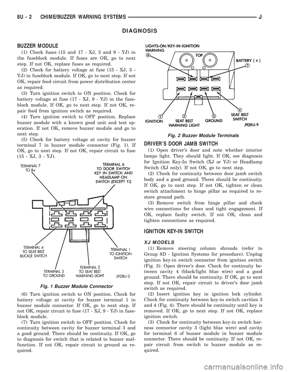
terminal 7 in buzzer module connector (Fig. 1). If
OK, go to next step. If not OK, repair circuit to fuse
(15 - XJ, 3 - YJ).
(6) Turn ignition switch to ON position. Check for
battery voltage at cavity for buzzer terminal 1 in
buzzer module connector. If OK, go to next step. If
not OK, repair circuit to fuse (17 - XJ, 9 - YJ) in fuse-
block module.
(7) Turn ignition switch to OFF position. Check for
continuity between cavity for buzzer terminal 3 and
a good ground. There should be continuity. If OK, go
to diagnosis for switch that is related to buzzer mal-
function. If not OK, repair circuit to ground as re-
quired.
DRIVER'S DOOR JAMB SWITCH
(1) Open driver's door and note whether interior
lamps light. They should light. If OK, see diagnosis
for Ignition Key-In Switch (XJ or YJ) or Headlamp
Switch (XJ only). If not OK, go to next step.
(2) Check for continuity between door jamb switch
body and a good ground. There should be continuity.
If OK, go to next step. If not OK, tighten or clean
switch attachment to hinge pillar as required to re-
store ground path.
(3) Remove switch from hinge pillar and check
wire connections for clean and tight engagement. If
OK, replace faulty switch. If not OK, clean and
tighten connections as required.
IGNITION KEY-IN SWITCH
XJ MODELS
(1) Remove steering column shrouds (refer to
Group 8D - Ignition Systems for procedure). Unplug
ignition key-in switch connector from ignition switch
(Fig. 3). Open driver's door. Check for continuity be-
tween cavity 4 (black/light blue wire) and a good
ground. There should be continuity. If OK, go to next
step. If not OK, repair circuit to driver's door jamb
switch as required.
(2) Insert ignition key in ignition lock cylinder.
Check for continuity between key-in switch cavities 3
and 4 (Fig. 4). There should be continuity until key is
removed. If OK, go to next step. If not OK, replace
ignition switch.
(3) Check for continuity between key-in switch har-
ness connector cavity 3 (light blue wire) and cavity
for terminal 6 of buzzer module in buzzer module
connector. There should be continuity. If not OK, re-
pair circuit from switch to buzzer module as re-
quired.
Fig. 1 Buzzer Module Connector
Fig. 2 Buzzer Module Terminals
8U - 2 CHIME/BUZZER WARNING SYSTEMSJ
Page 539 of 2158
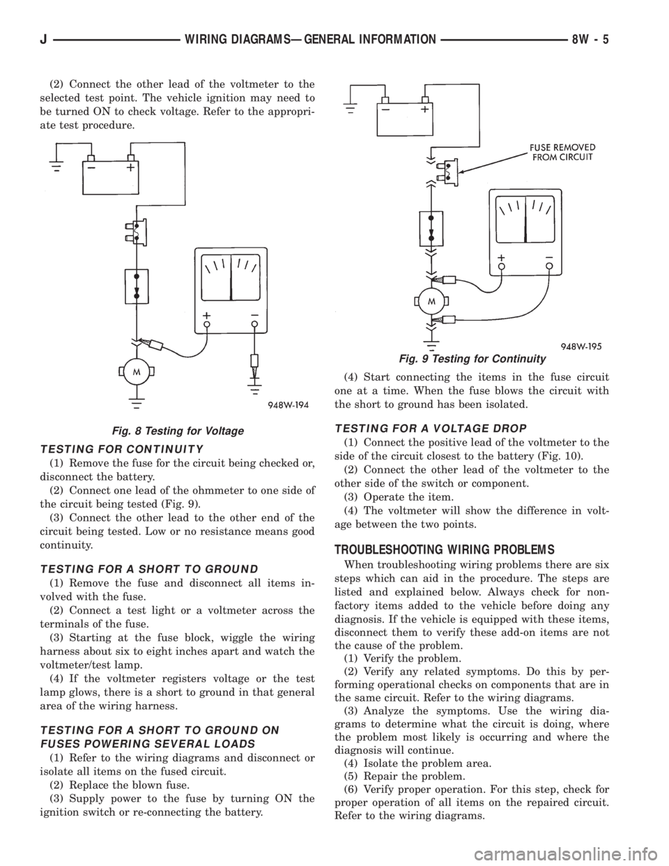
(2) Connect the other lead of the voltmeter to the
selected test point. The vehicle ignition may need to
be turned ON to check voltage. Refer to the appropri-
ate test procedure.
TESTING FOR CONTINUITY
(1) Remove the fuse for the circuit being checked or,
disconnect the battery.
(2) Connect one lead of the ohmmeter to one side of
the circuit being tested (Fig. 9).
(3) Connect the other lead to the other end of the
circuit being tested. Low or no resistance means good
continuity.
TESTING FOR A SHORT TO GROUND
(1) Remove the fuse and disconnect all items in-
volved with the fuse.
(2) Connect a test light or a voltmeter across the
terminals of the fuse.
(3) Starting at the fuse block, wiggle the wiring
harness about six to eight inches apart and watch the
voltmeter/test lamp.
(4) If the voltmeter registers voltage or the test
lamp glows, there is a short to ground in that general
area of the wiring harness.
TESTING FOR A SHORT TO GROUND ON
FUSES POWERING SEVERAL LOADS
(1) Refer to the wiring diagrams and disconnect or
isolate all items on the fused circuit.
(2) Replace the blown fuse.
(3) Supply power to the fuse by turning ON the
ignition switch or re-connecting the battery.(4) Start connecting the items in the fuse circuit
one at a time. When the fuse blows the circuit with
the short to ground has been isolated.
TESTING FOR A VOLTAGE DROP
(1) Connect the positive lead of the voltmeter to the
side of the circuit closest to the battery (Fig. 10).
(2) Connect the other lead of the voltmeter to the
other side of the switch or component.
(3) Operate the item.
(4) The voltmeter will show the difference in volt-
age between the two points.
TROUBLESHOOTING WIRING PROBLEMS
When troubleshooting wiring problems there are six
steps which can aid in the procedure. The steps are
listed and explained below. Always check for non-
factory items added to the vehicle before doing any
diagnosis. If the vehicle is equipped with these items,
disconnect them to verify these add-on items are not
the cause of the problem.
(1) Verify the problem.
(2) Verify any related symptoms. Do this by per-
forming operational checks on components that are in
the same circuit. Refer to the wiring diagrams.
(3) Analyze the symptoms. Use the wiring dia-
grams to determine what the circuit is doing, where
the problem most likely is occurring and where the
diagnosis will continue.
(4) Isolate the problem area.
(5) Repair the problem.
(6) Verify proper operation. For this step, check for
proper operation of all items on the repaired circuit.
Refer to the wiring diagrams.
Fig. 8 Testing for Voltage
Fig. 9 Testing for Continuity
JWIRING DIAGRAMSÐGENERAL INFORMATION 8W - 5
Page 543 of 2158
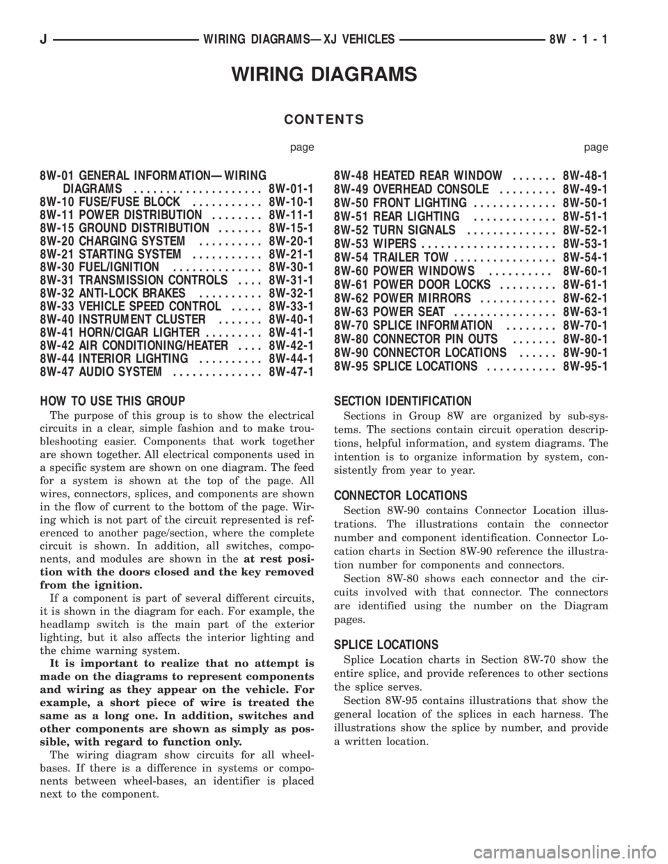
WIRING DIAGRAMS
CONTENTS
page page
8W-01 GENERAL INFORMATIONÐWIRING
DIAGRAMS.................... 8W-01-1
8W-10 FUSE/FUSE BLOCK........... 8W-10-1
8W-11 POWER DISTRIBUTION........ 8W-11-1
8W-15 GROUND DISTRIBUTION....... 8W-15-1
8W-20 CHARGING SYSTEM.......... 8W-20-1
8W-21 STARTING SYSTEM........... 8W-21-1
8W-30 FUEL/IGNITION.............. 8W-30-1
8W-31 TRANSMISSION CONTROLS.... 8W-31-1
8W-32 ANTI-LOCK BRAKES.......... 8W-32-1
8W-33 VEHICLE SPEED CONTROL..... 8W-33-1
8W-40 INSTRUMENT CLUSTER....... 8W-40-1
8W-41 HORN/CIGAR LIGHTER......... 8W-41-1
8W-42 AIR CONDITIONING/HEATER.... 8W-42-1
8W-44 INTERIOR LIGHTING.......... 8W-44-1
8W-47 AUDIO SYSTEM.............. 8W-47-18W-48 HEATED REAR WINDOW....... 8W-48-1
8W-49 OVERHEAD CONSOLE......... 8W-49-1
8W-50 FRONT LIGHTING............. 8W-50-1
8W-51 REAR LIGHTING............. 8W-51-1
8W-52 TURN SIGNALS.............. 8W-52-1
8W-53 WIPERS..................... 8W-53-1
8W-54 TRAILER TOW................ 8W-54-1
8W-60 POWER WINDOWS.......... 8W-60-1
8W-61 POWER DOOR LOCKS......... 8W-61-1
8W-62 POWER MIRRORS............ 8W-62-1
8W-63 POWER SEAT................ 8W-63-1
8W-70 SPLICE INFORMATION........ 8W-70-1
8W-80 CONNECTOR PIN OUTS....... 8W-80-1
8W-90 CONNECTOR LOCATIONS...... 8W-90-1
8W-95 SPLICE LOCATIONS........... 8W-95-1
HOW TO USE THIS GROUP
The purpose of this group is to show the electrical
circuits in a clear, simple fashion and to make trou-
bleshooting easier. Components that work together
are shown together. All electrical components used in
a specific system are shown on one diagram. The feed
for a system is shown at the top of the page. All
wires, connectors, splices, and components are shown
in the flow of current to the bottom of the page. Wir-
ing which is not part of the circuit represented is ref-
erenced to another page/section, where the complete
circuit is shown. In addition, all switches, compo-
nents, and modules are shown in theat rest posi-
tion with the doors closed and the key removed
from the ignition.
If a component is part of several different circuits,
it is shown in the diagram for each. For example, the
headlamp switch is the main part of the exterior
lighting, but it also affects the interior lighting and
the chime warning system.
It is important to realize that no attempt is
made on the diagrams to represent components
and wiring as they appear on the vehicle. For
example, a short piece of wire is treated the
same as a long one. In addition, switches and
other components are shown as simply as pos-
sible, with regard to function only.
The wiring diagram show circuits for all wheel-
bases. If there is a difference in systems or compo-
nents between wheel-bases, an identifier is placed
next to the component.
SECTION IDENTIFICATION
Sections in Group 8W are organized by sub-sys-
tems. The sections contain circuit operation descrip-
tions, helpful information, and system diagrams. The
intention is to organize information by system, con-
sistently from year to year.
CONNECTOR LOCATIONS
Section 8W-90 contains Connector Location illus-
trations. The illustrations contain the connector
number and component identification. Connector Lo-
cation charts in Section 8W-90 reference the illustra-
tion number for components and connectors.
Section 8W-80 shows each connector and the cir-
cuits involved with that connector. The connectors
are identified using the number on the Diagram
pages.
SPLICE LOCATIONS
Splice Location charts in Section 8W-70 show the
entire splice, and provide references to other sections
the splice serves.
Section 8W-95 contains illustrations that show the
general location of the splices in each harness. The
illustrations show the splice by number, and provide
a written location.
JWIRING DIAGRAMSÐXJ VEHICLES 8W - 1 - 1
Page 545 of 2158
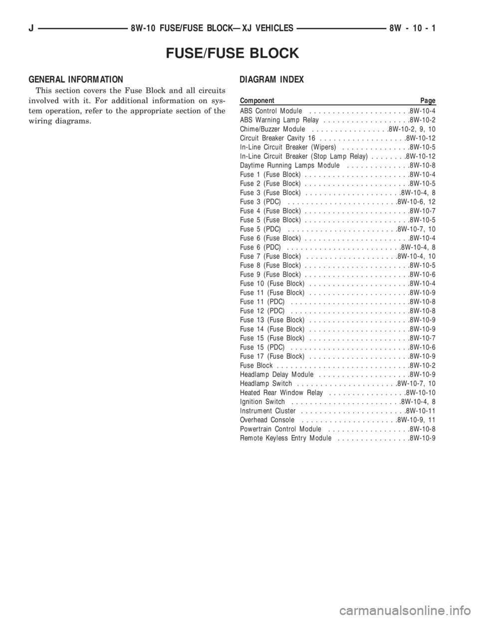
FUSE/FUSE BLOCK
GENERAL INFORMATION
This section covers the Fuse Block and all circuits
involved with it. For additional information on sys-
tem operation, refer to the appropriate section of the
wiring diagrams.
DIAGRAM INDEX
Component Page
ABS Control Module......................8W-10-4
ABS Warning Lamp Relay...................8W-10-2
Chime/Buzzer Module.................8W-10-2, 9, 10
Circuit Breaker Cavity 16...................8W-10-12
In-Line Circuit Breaker (Wipers)...............8W-10-5
In-Line Circuit Breaker (Stop Lamp Relay)........8W-10-12
Daytime Running Lamps Module..............8W-10-8
Fuse 1 (Fuse Block).......................8W-10-4
Fuse 2 (Fuse Block).......................8W-10-5
Fuse 3 (Fuse Block).....................8W-10-4, 8
Fuse 3 (PDC)........................8W-10-6, 12
Fuse 4 (Fuse Block).......................8W-10-7
Fuse 5 (Fuse Block).......................8W-10-5
Fuse 5 (PDC)........................8W-10-7, 10
Fuse 6 (Fuse Block).......................8W-10-4
Fuse 6 (PDC).........................8W-10-4, 8
Fuse 7 (Fuse Block)....................8W-10-4, 10
Fuse 8 (Fuse Block).......................8W-10-5
Fuse 9 (Fuse Block).......................8W-10-6
Fuse 10 (Fuse Block)......................8W-10-4
Fuse 11 (Fuse Block)......................8W-10-9
Fuse 11 (PDC)..........................8W-10-8
Fuse 12 (PDC)..........................8W-10-8
Fuse 13 (Fuse Block)......................8W-10-9
Fuse 14 (Fuse Block)......................8W-10-9
Fuse 15 (Fuse Block)......................8W-10-7
Fuse 15 (PDC)..........................8W-10-6
Fuse 17 (Fuse Block)......................8W-10-9
Fuse Block.............................8W-10-2
Headlamp Delay Module....................8W-10-9
Headlamp Switch......................8W-10-7, 10
Heated Rear Window Relay.................8W-10-10
Ignition Switch........................8W-10-4, 8
Instrument Cluster.......................8W-10-11
Overhead Console.....................8W-10-9, 11
Powertrain Control Module..................8W-10-8
Remote Keyless Entry Module................8W-10-9
J8W-10 FUSE/FUSE BLOCKÐXJ VEHICLES 8W - 10 - 1
Page 557 of 2158
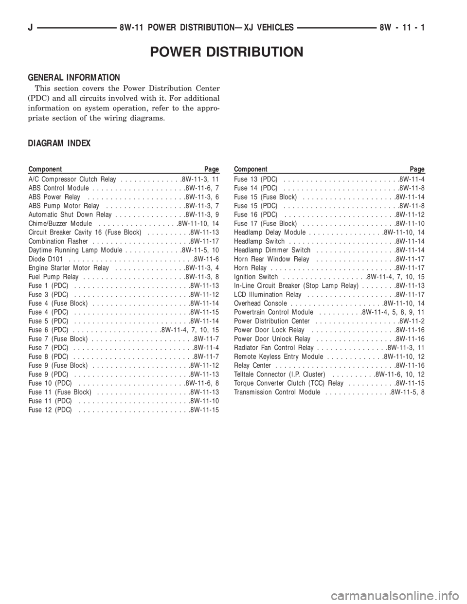
POWER DISTRIBUTION
GENERAL INFORMATION
This section covers the Power Distribution Center
(PDC) and all circuits involved with it. For additional
information on system operation, refer to the appro-
priate section of the wiring diagrams.
DIAGRAM INDEX
Component Page
A/C Compressor Clutch Relay..............8W-11-3, 11
ABS Control Module.....................8W-11-6, 7
ABS Power Relay......................8W-11-3, 6
ABS Pump Motor Relay..................8W-11-3, 7
Automatic Shut Down Relay................8W-11-3, 9
Chime/Buzzer Module..................8W-11-10, 14
Circuit Breaker Cavity 16 (Fuse Block)..........8W-11-13
Combination Flasher......................8W-11-17
Daytime Running Lamp Module.............8W-11-5, 10
Diode D101............................8W-11-6
Engine Starter Motor Relay................8W-11-3, 4
Fuel Pump Relay.......................8W-11-3, 8
Fuse 1 (PDC)..........................8W-11-13
Fuse 3 (PDC)..........................8W-11-12
Fuse 4 (Fuse Block)......................8W-11-14
Fuse 4 (PDC)..........................8W-11-15
Fuse 5 (PDC)..........................8W-11-14
Fuse 6 (PDC)....................8W-11-4, 7, 10, 15
Fuse 7 (Fuse Block).......................8W-11-7
Fuse 7 (PDC)...........................8W-11-4
Fuse 8 (PDC)...........................8W-11-7
Fuse 9 (Fuse Block)......................8W-11-12
Fuse 9 (PDC)..........................8W-11-13
Fuse 10 (PDC)........................8W-11-6, 8
Fuse 11 (Fuse Block).....................8W-11-13
Fuse 11 (PDC).........................8W-11-10
Fuse 12 (PDC).........................8W-11-15Component Page
Fuse 13 (PDC)..........................8W-11-4
Fuse 14 (PDC)..........................8W-11-8
Fuse 15 (Fuse Block).....................8W-11-14
Fuse 15 (PDC)..........................8W-11-8
Fuse 16 (PDC).........................8W-11-12
Fuse 17 (Fuse Block).....................8W-11-10
Headlamp Delay Module.................8W-11-10, 14
Headlamp Switch........................8W-11-14
Headlamp Dimmer Switch..................8W-11-14
Horn Rear Window Relay..................8W-11-17
Horn Relay............................8W-11-17
Ignition Switch...................8W-11-4, 7, 10, 15
In-Line Circuit Breaker (Stop Lamp Relay)........8W-11-13
LCD Illumination Relay....................8W-11-17
Overhead Console.....................8W-11-10, 14
Powertrain Control Module..........8W-11-4, 5, 8, 9, 11
Power Distribution Center...................8W-11-2
Power Door Lock Relay...................8W-11-16
Power Door Unlock Relay..................8W-11-16
Radiator Fan Control Relay................8W-11-3, 11
Remote Keyless Entry Module.............8W-11-10, 12
Relay Center...........................8W-11-16
Telltale Connector (I.P. Cluster)..........8W-11-6, 10, 12
Torque Converter Clutch (TCC) Relay...........8W-11-15
Transmission Control Module...............8W-11-5, 8
J8W-11 POWER DISTRIBUTIONÐXJ VEHICLES 8W - 11 - 1
Page 581 of 2158
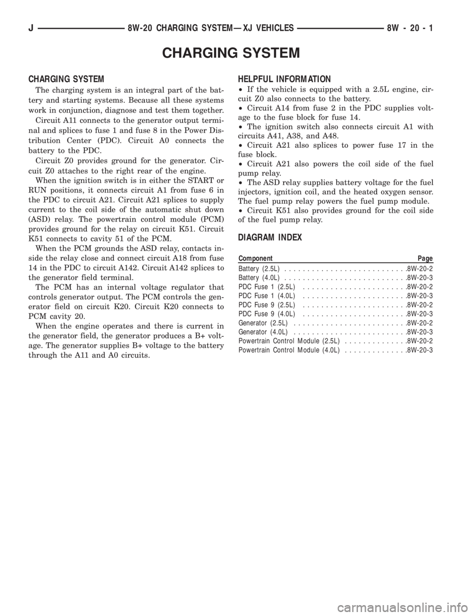
CHARGING SYSTEM
CHARGING SYSTEM
The charging system is an integral part of the bat-
tery and starting systems. Because all these systems
work in conjunction, diagnose and test them together.
Circuit A11 connects to the generator output termi-
nal and splices to fuse 1 and fuse 8 in the Power Dis-
tribution Center (PDC). Circuit A0 connects the
battery to the PDC.
Circuit Z0 provides ground for the generator. Cir-
cuit Z0 attaches to the right rear of the engine.
When the ignition switch is in either the START or
RUN positions, it connects circuit A1 from fuse 6 in
the PDC to circuit A21. Circuit A21 splices to supply
current to the coil side of the automatic shut down
(ASD) relay. The powertrain control module (PCM)
provides ground for the relay on circuit K51. Circuit
K51 connects to cavity 51 of the PCM.
When the PCM grounds the ASD relay, contacts in-
side the relay close and connect circuit A18 from fuse
14 in the PDC to circuit A142. Circuit A142 splices to
the generator field terminal.
The PCM has an internal voltage regulator that
controls generator output. The PCM controls the gen-
erator field on circuit K20. Circuit K20 connects to
PCM cavity 20.
When the engine operates and there is current in
the generator field, the generator produces a B+ volt-
age. The generator supplies B+ voltage to the battery
through the A11 and A0 circuits.
HELPFUL INFORMATION
²If the vehicle is equipped with a 2.5L engine, cir-
cuit Z0 also connects to the battery.
²Circuit A14 from fuse 2 in the PDC supplies volt-
age to the fuse block for fuse 14.
²The ignition switch also connects circuit A1 with
circuits A41, A38, and A48.
²Circuit A21 also splices to power fuse 17 in the
fuse block.
²Circuit A21 also powers the coil side of the fuel
pump relay.
²The ASD relay supplies battery voltage for the fuel
injectors, ignition coil, and the heated oxygen sensor.
The fuel pump relay powers the fuel pump module.
²Circuit K51 also provides ground for the coil side
of the fuel pump relay.
DIAGRAM INDEX
Component Page
Battery (2.5L)...........................8W-20-2
Battery (4.0L)...........................8W-20-3
PDC Fuse 1 (2.5L).......................8W-20-2
PDC Fuse 1 (4.0L).......................8W-20-3
PDC Fuse 9 (2.5L).......................8W-20-2
PDC Fuse 9 (4.0L).......................8W-20-3
Generator (2.5L).........................8W-20-2
Generator (4.0L).........................8W-20-3
Powertrain Control Module (2.5L)..............8W-20-2
Powertrain Control Module (4.0L)..............8W-20-3
J8W-20 CHARGING SYSTEMÐXJ VEHICLES 8W - 20 - 1
Page 585 of 2158
STARTING SYSTEM
INDEX
page page
Diagram Index............................ 1Starting System........................... 1
STARTING SYSTEM
AUTOMATIC TRANSMISSIONS
Circuit A0 from the battery is double crimped at
the positive battery post. One branch of circuit A0
(battery positive cable) connects to the engine starter
motor. The other A0 branch supplies voltage to the
bus bar in the power distribution center (PDC).
Fuse 7 in the PDC supplies battery voltage to the
contact side of the engine starter motor relay on cir-
cuit A4. When the coil side of the engine starter mo-
tor relay energizes, the contacts close and connect
circuit A4 to circuit T40. Circuit T40 supplies battery
voltage to the starter motor solenoid.
The ignition switch supplies battery voltage to the
coil side of the starter motor relay on circuit A41
when the key is moved to the START position and
the PARK/NEUTRAL position switch is closed.
Ground for the coil side of the starter motor relay is
supplied by the case grounded PARK/NEUTRAL po-
sition switch. Circuit T41 connects the coil side of the
relay to the PARK/NEUTRAL position switch.
When the starter motor relay energizes and the
contacts close, circuit T40 supplies battery voltage to
the starter motor solenoid. Circuit A0 from the bat-
tery supplies voltage to the starter motor when the
solenoid energizes.
MANUAL TRANSMISSIONS
Circuit A0 from the battery is double crimped at
the positive battery post. One branch of circuit A0
(battery positive cable) connects to the battery
starter motor. The other A0 branch supplies voltage
to the buss bar in the power distribution center
(PDC).
Fuse 7 in the PDC supplies battery voltage to the
contact side of the engine starter motor relay on cir-
cuit A4. When the coil side of the engine starter mo-
tor relay energizes, the contacts close and connect
circuit A4 to circuit T40. Circuit T40 supplies battery
voltage to the starter motor solenoid.The ignition switch supplies battery voltage to the
coil side of the starter motor relay on circuit A41
when the key is moved to the START position. Cir-
cuit Z12 provides ground for the coil side of the relay.
When the starter motor relay energizes and the
contacts close, circuit T40 supplies battery voltage to
the starter motor solenoid. Circuit A0 from the bat-
tery supplies voltage to the starter motor when the
solenoid energizes.
HELPFUL INFORMATION
²The Park/Neutral switch closes when the trans-
mission is in either the PARK or NEUTRAL posi-
tions.
²Circuit T41 also connects to cavity 30 of the pow-
ertrain control module (PCM). This input tells the
PCM the operator is starting the vehicle.
²Circuit A4 is double crimped at the contact side of
the starter motor relay. The A4 branch leaving the
relay powers fuse 13 in the PDC.
DIAGRAM INDEX
Component Page
Battery (2.5L)...........................8W-21-2
Battery (4.0L)...........................8W-21-3
Engine Starter Motor (2.5L)..................8W-21-2
Engine Starter Motor (4.0L)..................8W-21-3
Engine Starter Motor Relay (2.5L)..............8W-21-2
Engine Starter Motor Relay (4.0L)..............8W-21-3
Ignition Switch (2.5L)......................8W-21-2
Ignition Switch (4.0L)......................8W-21-3
PDC Fuse 6 (2.5L).......................8W-21-2
PDC Fuse 6 (4.0L).......................8W-21-3
PDC Fuse 7 (2.5L).......................8W-21-2
PDC Fuse 7 (4.0L).......................8W-21-3
Powertrain Control Module (2.5L)..............8W-21-2
Powertrain Control Module (4.0L)..............8W-21-3
Park/Neutral Position Switch (2.5L).............8W-21-2
Park/Neutral Position Switch (4.0L).............8W-21-3
J8W-21 STARTING SYSTEMÐXJ VEHICLES 8W - 21 - 1