spark plugs replace JEEP YJ 1995 Service And User Guide
[x] Cancel search | Manufacturer: JEEP, Model Year: 1995, Model line: YJ, Model: JEEP YJ 1995Pages: 2158, PDF Size: 81.9 MB
Page 338 of 2158
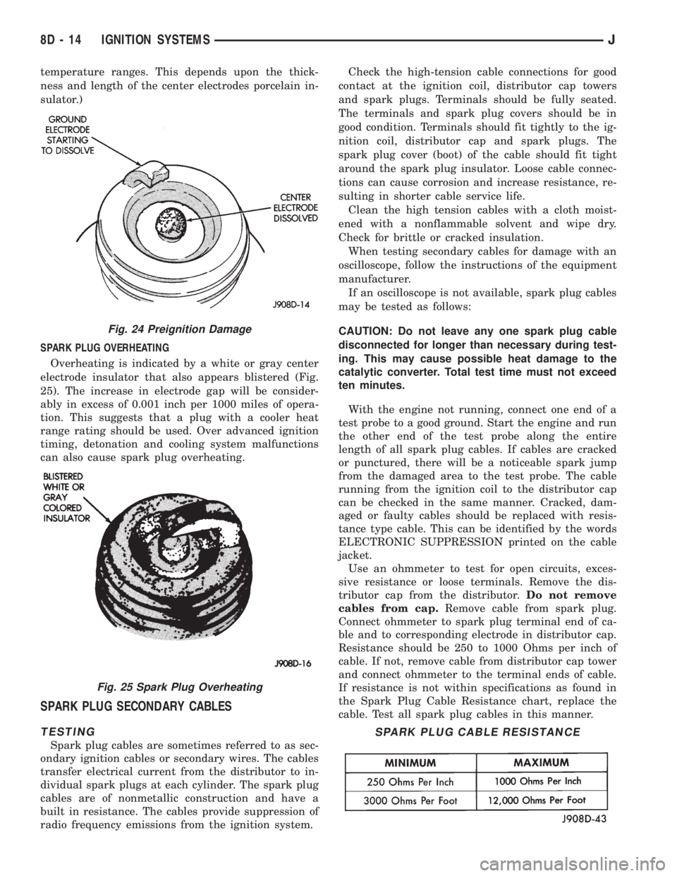
temperature ranges. This depends upon the thick-
ness and length of the center electrodes porcelain in-
sulator.)
SPARK PLUG OVERHEATING
Overheating is indicated by a white or gray center
electrode insulator that also appears blistered (Fig.
25). The increase in electrode gap will be consider-
ably in excess of 0.001 inch per 1000 miles of opera-
tion. This suggests that a plug with a cooler heat
range rating should be used. Over advanced ignition
timing, detonation and cooling system malfunctions
can also cause spark plug overheating.
SPARK PLUG SECONDARY CABLES
TESTING
Spark plug cables are sometimes referred to as sec-
ondary ignition cables or secondary wires. The cables
transfer electrical current from the distributor to in-
dividual spark plugs at each cylinder. The spark plug
cables are of nonmetallic construction and have a
built in resistance. The cables provide suppression of
radio frequency emissions from the ignition system.Check the high-tension cable connections for good
contact at the ignition coil, distributor cap towers
and spark plugs. Terminals should be fully seated.
The terminals and spark plug covers should be in
good condition. Terminals should fit tightly to the ig-
nition coil, distributor cap and spark plugs. The
spark plug cover (boot) of the cable should fit tight
around the spark plug insulator. Loose cable connec-
tions can cause corrosion and increase resistance, re-
sulting in shorter cable service life.
Clean the high tension cables with a cloth moist-
ened with a nonflammable solvent and wipe dry.
Check for brittle or cracked insulation.
When testing secondary cables for damage with an
oscilloscope, follow the instructions of the equipment
manufacturer.
If an oscilloscope is not available, spark plug cables
may be tested as follows:
CAUTION: Do not leave any one spark plug cable
disconnected for longer than necessary during test-
ing. This may cause possible heat damage to the
catalytic converter. Total test time must not exceed
ten minutes.
With the engine not running, connect one end of a
test probe to a good ground. Start the engine and run
the other end of the test probe along the entire
length of all spark plug cables. If cables are cracked
or punctured, there will be a noticeable spark jump
from the damaged area to the test probe. The cable
running from the ignition coil to the distributor cap
can be checked in the same manner. Cracked, dam-
aged or faulty cables should be replaced with resis-
tance type cable. This can be identified by the words
ELECTRONIC SUPPRESSION printed on the cable
jacket.
Use an ohmmeter to test for open circuits, exces-
sive resistance or loose terminals. Remove the dis-
tributor cap from the distributor.Do not remove
cables from cap.Remove cable from spark plug.
Connect ohmmeter to spark plug terminal end of ca-
ble and to corresponding electrode in distributor cap.
Resistance should be 250 to 1000 Ohms per inch of
cable. If not, remove cable from distributor cap tower
and connect ohmmeter to the terminal ends of cable.
If resistance is not within specifications as found in
the Spark Plug Cable Resistance chart, replace the
cable. Test all spark plug cables in this manner.
Fig. 24 Preignition Damage
Fig. 25 Spark Plug Overheating
SPARK PLUG CABLE RESISTANCE
8D - 14 IGNITION SYSTEMSJ
Page 402 of 2158

ANTENNA
All models use a fixed-length stainless steel rod-
type antenna mast, installed at the right front (fend-
er on XJ, cowl side on YJ) of the vehicle. The
antenna mast is connected to the center wire of the
coaxial antenna cable and is not grounded to any
part of the vehicle.
To eliminate static, the antenna base must have a
good ground. The coaxial antenna cable shield (the
outer wire mesh of the cable) is grounded to the an-
tenna base and the radio chassis.
The factory installed ETRs automatically compen-
sate for radio antenna trim. Therefore, no antenna
trimmer adjustment is required or possible when re-
placing the receiver or the antenna.
RADIO NOISE SUPPRESSION
Radio Frequency Interference (RFI) and Electro-
Magnetic Interference (EMI) noise suppression is ac-
complished primarily through circuitry internal to
the radio receivers. These internal suppression de-
vices are only serviced as a part of the radio receiver.External suppression devices that are serviceable
and should be checked in the case of RFI or EMI
noise complaints include the following:
²radio antenna base ground
²engine-to-body ground strap
²resistor-type spark plugs
²radio suppression-type secondary ignition wiring.
In addition, if the source of RFI or EMI noise is
identified as a component on the vehicle (i.e.:genera-
tor, blower motor, etc.), the ground path for that com-
ponent should be checked. If excessive resistance is
found in that circuit, repair as required before con-
sidering any component replacement.
Fleet vehicles are available with an extra-cost RFI-
suppressed Powertrain Control Module (PCM). This
unit reduces interference generated by the PCM on
some radio frequencies used in two-way radio com-
munications. However, this unit will not resolve com-
plaints of RFI in the commercial AM or FM radio
frequency ranges.
DIAGNOSIS
RADIO
CAUTION: Do not operate the radio with speaker
leads detached since damage to the transistors
may result.
(1) Check fuse 2 in fuseblock module and fuse in
back of radio chassis. If OK, go to next step. If not
OK, replace fuse.
(2) Turn ignition switch to ON position. Check for
battery voltage at fuse 2. If OK, go to next step. If
not OK, repair circuit to ignition switch as required.
(3) Turn ignition switch to OFF position. Discon-
nect battery negative cable. Remove instrument clus-
ter bezel. Remove radio, but do not unplug any
connections. Check for continuity between the radio
chassis and a good ground. There should be continu-
ity. If OK, go to next step. If not OK, repair radio
ground circuit as required.
(4) Connect battery negative cable. Turn ignition
switch to ON position. See Radio Connections chart.
Check for battery voltage at cavity 3 of radio connec-
tor. If OK, go to next step. If not OK, repair circuit to
fuse 2 as required.
(5) Turn ignition switch to OFF position. Check for
battery voltage at cavity 4 of radio connector. If OK,
replace radio. If not OK, repair circuit to IOD fuse in
PDC as required.
SPEAKERS
CAUTION: Do not operate the radio with speaker
leads detached since damage to the transistors
may result.
(1) Turn radio on and adjust balance and fader
controls to check performance of each individual
speaker. Note the speaker locations that are not per-
forming correctly. Go to next step.
(2) Turn radio off. Disconnect battery negative ca-
ble. Remove instrument cluster bezel and remove ra-
dio. See Radio Connections chart. Check both the
speaker feed and return cavities at radio for continu-
ity to a good ground. There should be no continuity.
If OK, go to next step. If not OK, repair wiring cir-
cuit as required.
(3) Check resistance between speaker feed and re-
turn cavities. Meter should read between 3 and 8
ohms (speaker impedance). If OK, see diagnosis for
Radio. If not OK, go to next step.
(4) Unplug speaker wiring connector. Check for
continuity between speaker feed cavity at radio and
at speaker. Repeat check between speaker return
cavity at radio and at speaker. If OK, replace
speaker. If not OK, repair wiring circuit as required.
8F - 2 AUDIO SYSTEMSJ
Page 405 of 2158
(5) The coil ground terminal (85) is connected to
the electromagnet in the relay. Check as follows:
(a) On YJ models, it is grounded at all times.
There should be continuity to ground at cavity for
relay terminal 85 at all times. If not, repair circuit
to ground as required.
(b) On XJ models, it is energized when the head-
lamp switch is on. There should be battery voltage
at cavity for relay terminal 85 with the headlamp
switch on. If not, repair circuit to headlamp switch
as required.
ANTENNA
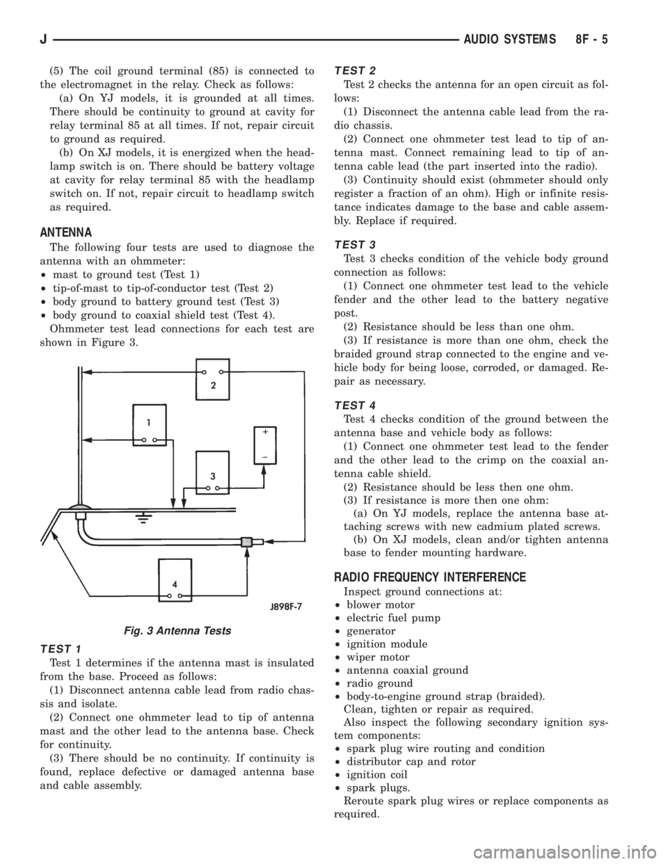
The following four tests are used to diagnose the
antenna with an ohmmeter:
²mast to ground test (Test 1)
²tip-of-mast to tip-of-conductor test (Test 2)
²body ground to battery ground test (Test 3)
²body ground to coaxial shield test (Test 4).
Ohmmeter test lead connections for each test are
shown in Figure 3.
TEST 1
Test 1 determines if the antenna mast is insulated
from the base. Proceed as follows:
(1) Disconnect antenna cable lead from radio chas-
sis and isolate.
(2) Connect one ohmmeter lead to tip of antenna
mast and the other lead to the antenna base. Check
for continuity.
(3) There should be no continuity. If continuity is
found, replace defective or damaged antenna base
and cable assembly.
TEST 2
Test 2 checks the antenna for an open circuit as fol-
lows:
(1) Disconnect the antenna cable lead from the ra-
dio chassis.
(2) Connect one ohmmeter test lead to tip of an-
tenna mast. Connect remaining lead to tip of an-
tenna cable lead (the part inserted into the radio).
(3) Continuity should exist (ohmmeter should only
register a fraction of an ohm). High or infinite resis-
tance indicates damage to the base and cable assem-
bly. Replace if required.
TEST 3
Test 3 checks condition of the vehicle body ground
connection as follows:
(1) Connect one ohmmeter test lead to the vehicle
fender and the other lead to the battery negative
post.
(2) Resistance should be less than one ohm.
(3) If resistance is more than one ohm, check the
braided ground strap connected to the engine and ve-
hicle body for being loose, corroded, or damaged. Re-
pair as necessary.
TEST 4
Test 4 checks condition of the ground between the
antenna base and vehicle body as follows:
(1) Connect one ohmmeter test lead to the fender
and the other lead to the crimp on the coaxial an-
tenna cable shield.
(2) Resistance should be less then one ohm.
(3) If resistance is more then one ohm:
(a) On YJ models, replace the antenna base at-
taching screws with new cadmium plated screws.
(b) On XJ models, clean and/or tighten antenna
base to fender mounting hardware.
RADIO FREQUENCY INTERFERENCE
Inspect ground connections at:
²blower motor
²electric fuel pump
²generator
²ignition module
²wiper motor
²antenna coaxial ground
²radio ground
²body-to-engine ground strap (braided).
Clean, tighten or repair as required.
Also inspect the following secondary ignition sys-
tem components:
²spark plug wire routing and condition
²distributor cap and rotor
²ignition coil
²spark plugs.
Reroute spark plug wires or replace components as
required.
Fig. 3 Antenna Tests
JAUDIO SYSTEMS 8F - 5
Page 1281 of 2158
minutes). The use of a locating dowel is recom-
mended during assembly to prevent smearing the
material off location.
Mopar Gasket Maker should be applied sparingly
to one gasket surface. The sealant diameter should
be 1.00 mm (0.04 inch) or less. Be certain the mate-
rial surrounds each mounting hole. Excess material
can easily be wiped off. Components should be
torqued in place within 15 minutes. The use of a lo-
cating dowel is recommended during assembly to pre-
vent smearing the material off location.
ENGINE PERFORMANCE
To provide best vehicle performance and lowest ve-
hicle emissions, it is most important that the tune-up
be done accurately. Use the specifications listed on
the Vehicle Emission Control Information label found
on the engine compartment hood.
(1) Test battery specific gravity. Add water, if nec-
essary. Clean and tighten battery connections.
(2) Test cranking amperage draw (refer to Group
8B, Battery/Starter Service for the proper proce-
dures).
(3) Tighten the intake manifold bolts (refer to
Group 11, Exhaust System and Intake Manifold for
the proper specifications).
(4) Perform cylinder compression test:
(a) Check engine oil level and add oil, if neces-
sary.
(b) Drive the vehicle until engine reaches normal
operating temperature.
(c) Select a route free from traffic and other
forms of congestion, observe all traffic laws and
briskly accelerate through the gears several times.
The higher engine speed may help clean out valve
seat deposits which can prevent accurate compres-
sion readings.
CAUTION: DO NOT overspeed the engine.
(d) Remove all spark plugs from engine. As spark
plugs are being removed, check electrodes for ab-
normal firing indicatorsÐfouled, hot, oily, etc.
Record cylinder number of spark plug for future
reference.
(e) Disconnect coil wire from distributor and se-
cure to good ground to prevent a spark from start-
ing a fire.
(f) Be sure throttle blades are fully open during
the compression check.
(g) Insert compression gage adaptor into the
No.1 spark plug hole. Crank engine until maximum
pressure is reached on gauge. Record this pressure
as No.1 cylinder pressure.
(h) Repeat Step 4g for all remaining cylinders.
(i) Compression should not be less than 689 kPa
(100 psi) and not vary more than 172 kPa (25 psi)
from cylinder to cylinder.(j) If cylinder(s) have abnormally low compres-
sion pressures, repeat steps 4a through 4h.
(k) If the same cylinder(s) repeat an abnormally
low reading, it could indicate the existence of a
problem in the cylinder.
The recommended compression pressures are
to be used only as a guide to diagnosing engine
problems. An engine should NOT be disassem-
bled to determine the cause of low compression
unless some malfunction is present.
(5) Clean or replace spark plugs as necessary. Ad-
just gap (refer to Group 8D, Ignition System for gap
adjustment and torque).
(6) Test resistance of spark plug cables (refer to
Group 8D, Ignition System).
(7) Inspect the primary wire. Test coil output volt-
age, primary and secondary resistance. Replace parts
as necessary (refer to Group 8D, Ignition System and
make necessary adjustment).
(8) Perform a combustion analysis.
(9) Test fuel pump for pressure (refer to Group 14,
Fuel System for the proper specifications).
(10) Inspect air filter element (refer to Group 0,
Lubrication and Maintenance for the proper proce-
dure).
(11) Inspect crankcase ventilation system (refer to
Group 0, Lubrication and Maintenance for the proper
procedure).
(12) For emission controls refer to Group 25, Emis-
sion Controls System for service procedures.
(13) Inspect and adjust accessory belt drives (refer
to Group 7, Cooling System for the proper adjust-
ments).
(14) Road test vehicle as a final test.
HONING CYLINDER BORES
Before honing, stuff plenty of clean shop towels un-
der the bores and over the crankshaft to keep abra-
sive materials from entering the crankshaft area.
(1) Used carefully, the Cylinder Bore Sizing Hone
C-823 equipped with 220 grit stones, is the best tool
for this job. In addition to deglazing, it will reduce
taper and out-of-round as well as removing light
scuffing, scoring or scratches. Usually a few strokes
will clean up a bore and maintain the required lim-
its.
CAUTION: DO NOT use rigid type hones to remove
cylinder wall glaze.
(2) Deglazing of the cylinder walls may be done if
the cylinder bore is straight and round. Use a cylin-
der surfacing hone, Honing Tool C-3501, equipped
with 280 grit stones (C-3501-3810). 20-60 strokes, de-
pending on the bore condition, will be sufficient to
provide a satisfactory surface. Using honing oil
C-3501-3880 or a light honing oil available from ma-
jor oil distributors.
9 - 2 ENGINESJ
Page 1283 of 2158
CONNECTING ROD BEARING CLEARANCE
Engine connecting rod bearing clearances can be
determined by use of Plastigage, or equivalent. The
following is the recommended procedures for the use
of Plastigage:
(1) Remove oil film from surface to be checked.
Plastigage is soluble in oil.
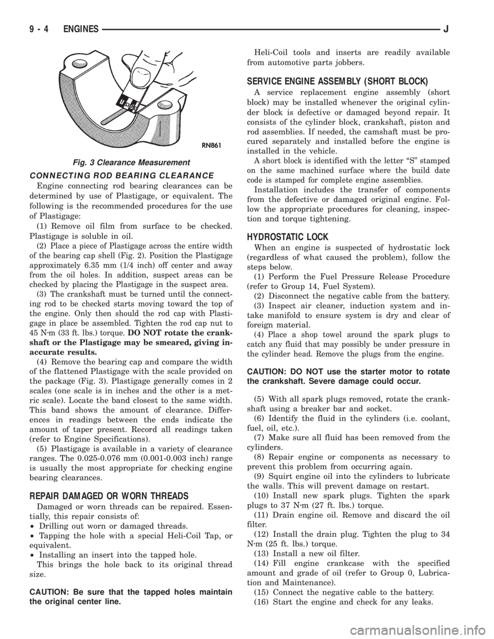
(2) Place a piece of Plastigage across the entire width
of the bearing cap shell (Fig. 2). Position the Plastigage
approximately 6.35 mm (1/4 inch) off center and away
from the oil holes. In addition, suspect areas can be
checked by placing the Plastigage in the suspect area.
(3) The crankshaft must be turned until the connect-
ing rod to be checked starts moving toward the top of
the engine. Only then should the rod cap with Plasti-
gage in place be assembled. Tighten the rod cap nut to
45 Nzm (33 ft. lbs.) torque.DO NOT rotate the crank-
shaft or the Plastigage may be smeared, giving in-
accurate results.
(4) Remove the bearing cap and compare the width
of the flattened Plastigage with the scale provided on
the package (Fig. 3). Plastigage generally comes in 2
scales (one scale is in inches and the other is a met-
ric scale). Locate the band closest to the same width.
This band shows the amount of clearance. Differ-
ences in readings between the ends indicate the
amount of taper present. Record all readings taken
(refer to Engine Specifications).
(5) Plastigage is available in a variety of clearance
ranges. The 0.025-0.076 mm (0.001-0.003 inch) range
is usually the most appropriate for checking engine
bearing clearances.
REPAIR DAMAGED OR WORN THREADS
Damaged or worn threads can be repaired. Essen-
tially, this repair consists of:
²Drilling out worn or damaged threads.
²Tapping the hole with a special Heli-Coil Tap, or
equivalent.
²Installing an insert into the tapped hole.
This brings the hole back to its original thread
size.
CAUTION: Be sure that the tapped holes maintain
the original center line.Heli-Coil tools and inserts are readily available
from automotive parts jobbers.
SERVICE ENGINE ASSEMBLY (SHORT BLOCK)
A service replacement engine assembly (short
block) may be installed whenever the original cylin-
der block is defective or damaged beyond repair. It
consists of the cylinder block, crankshaft, piston and
rod assemblies. If needed, the camshaft must be pro-
cured separately and installed before the engine is
installed in the vehicle.
A short block is identified with the letter ``S'' stamped
on the same machined surface where the build date
code is stamped for complete engine assemblies.
Installation includes the transfer of components
from the defective or damaged original engine. Fol-
low the appropriate procedures for cleaning, inspec-
tion and torque tightening.
HYDROSTATIC LOCK
When an engine is suspected of hydrostatic lock
(regardless of what caused the problem), follow the
steps below.
(1) Perform the Fuel Pressure Release Procedure
(refer to Group 14, Fuel System).
(2) Disconnect the negative cable from the battery.
(3) Inspect air cleaner, induction system and in-
take manifold to ensure system is dry and clear of
foreign material.
(4) Place a shop towel around the spark plugs to
catch any fluid that may possibly be under pressure in
the cylinder head. Remove the plugs from the engine.
CAUTION: DO NOT use the starter motor to rotate
the crankshaft. Severe damage could occur.
(5) With all spark plugs removed, rotate the crank-
shaft using a breaker bar and socket.
(6) Identify the fluid in the cylinders (i.e. coolant,
fuel, oil, etc.).
(7) Make sure all fluid has been removed from the
cylinders.
(8) Repair engine or components as necessary to
prevent this problem from occurring again.
(9) Squirt engine oil into the cylinders to lubricate
the walls. This will prevent damage on restart.
(10) Install new spark plugs. Tighten the spark
plugs to 37 Nzm (27 ft. lbs.) torque.
(11) Drain engine oil. Remove and discard the oil
filter.
(12) Install the drain plug. Tighten the plug to 34
Nzm (25 ft. lbs.) torque.
(13) Install a new oil filter.
(14) Fill engine crankcase with the specified
amount and grade of oil (refer to Group 0, Lubrica-
tion and Maintenance).
(15) Connect the negative cable to the battery.
(16) Start the engine and check for any leaks.
Fig. 3 Clearance Measurement
9 - 4 ENGINESJ
Page 1305 of 2158
(9) If equipped, disconnect the power steering
pump bracket. Set the pump and bracket aside. DO
NOT disconnect the hoses.
(10) Remove the fuel lines and vacuum advance
hose.
(11) Remove the intake and engine exhaust mani-
folds from the engine cylinder head (refer to Group
11, Exhaust System and Intake Manifold for the
proper procedures).
(12) Disconnect the ignition wires and remove the
spark plugs.
(13) Disconnect the temperature sending unit wire
connector.
(14) Remove the ignition coil and bracket assem-
bly.
(15) Remove the engine cylinder head bolts.
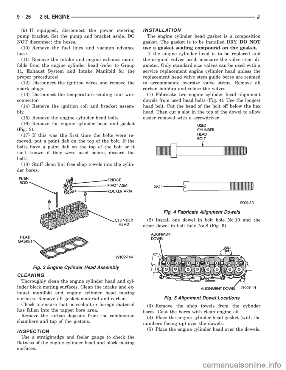
(16) Remove the engine cylinder head and gasket
(Fig. 3).
(17) If this was the first time the bolts were re-
moved, put a paint dab on the top of the bolt. If the
bolts have a paint dab on the top of the bolt or it
isn't known if they were used before, discard the
bolts.
(18) Stuff clean lint free shop towels into the cylin-
der bores.
CLEANING
Thoroughly clean the engine cylinder head and cyl-
inder block mating surfaces. Clean the intake and ex-
haust manifold and engine cylinder head mating
surfaces. Remove all gasket material and carbon.
Check to ensure that no coolant or foreign material
has fallen into the tappet bore area.
Remove the carbon deposits from the combustion
chambers and top of the pistons.
INSPECTION
Use a straightedge and feeler gauge to check the
flatness of the engine cylinder head and block mating
surfaces.
INSTALLATION
The engine cylinder head gasket is a composition
gasket. The gasket is to be installed DRY.DO NOT
use a gasket sealing compound on the gasket.
If the engine cylinder head is to be replaced and
the original valves used, measure the valve stem di-
ameter. Only standard size valves can be used with a
service replacement engine cylinder head unless the
replacement head valve stem guide bores are reamed
to accommodate oversize valve stems. Remove all
carbon buildup and reface the valves.
(1) Fabricate two engine cylinder head alignment
dowels from used head bolts (Fig. 4). Use the longest
head bolt. Cut the head of the bolt off below the hex
head. Then cut a slot in the top of the dowel to allow
easier removal with a screwdriver.
(2) Install one dowel in bolt hole No.10 and the
other dowel in bolt hole No.8 (Fig. 5).
(3) Remove the shop towels from the cylinder
bores. Coat the bores with clean engine oil.
(4) Place the engine cylinder head gasket (with the
numbers facing up) over the dowels.
(5) Place the engine cylinder head over the dowels.
Fig. 3 Engine Cylinder Head Assembly
Fig. 4 Fabricate Alignment Dowels
Fig. 5 Alignment Dowel Locations
9 - 26 2.5L ENGINEJ
Page 1306 of 2158
CAUTION: Engine cylinder head bolts should be re-
used only once. Replace the head bolts if they were
used before or if they have a paint dab on the top
of the bolt.
(6) Coat the threads of bolt No.7, only, with Loctite
PST sealant or equivalent.
(7) Install all head bolts, except No.8 and No.10.
(8) Remove the dowels.
(9) Install No.8 and No.10 head bolts.
(10) Tighten the engine cylinder head bolts in se-
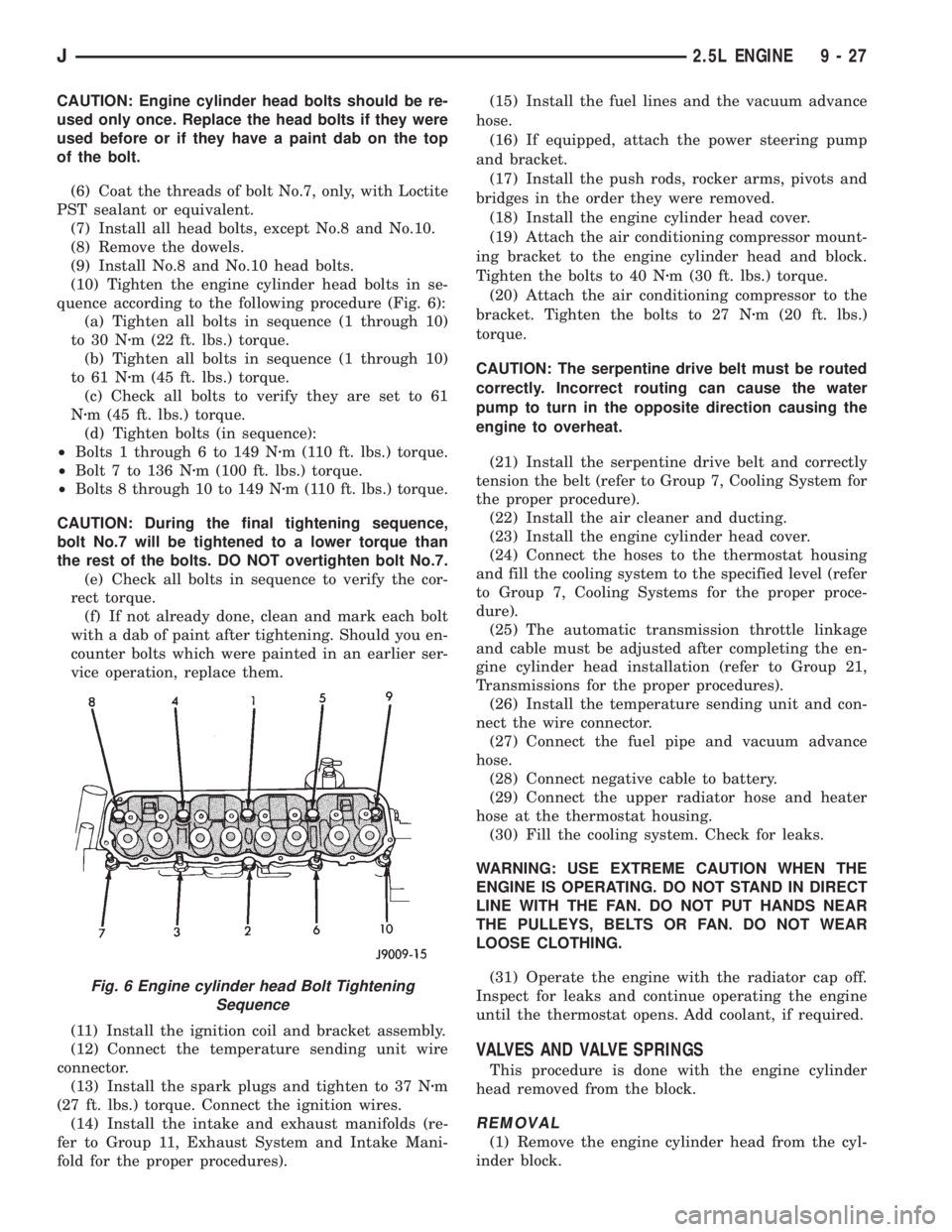
quence according to the following procedure (Fig. 6):
(a) Tighten all bolts in sequence (1 through 10)
to 30 Nzm (22 ft. lbs.) torque.
(b) Tighten all bolts in sequence (1 through 10)
to 61 Nzm (45 ft. lbs.) torque.
(c) Check all bolts to verify they are set to 61
Nzm (45 ft. lbs.) torque.
(d) Tighten bolts (in sequence):
²Bolts 1 through 6 to 149 Nzm (110 ft. lbs.) torque.
²Bolt 7 to 136 Nzm (100 ft. lbs.) torque.
²Bolts 8 through 10 to 149 Nzm (110 ft. lbs.) torque.
CAUTION: During the final tightening sequence,
bolt No.7 will be tightened to a lower torque than
the rest of the bolts. DO NOT overtighten bolt No.7.
(e) Check all bolts in sequence to verify the cor-
rect torque.
(f) If not already done, clean and mark each bolt
with a dab of paint after tightening. Should you en-
counter bolts which were painted in an earlier ser-
vice operation, replace them.
(11) Install the ignition coil and bracket assembly.
(12) Connect the temperature sending unit wire
connector.
(13) Install the spark plugs and tighten to 37 Nzm
(27 ft. lbs.) torque. Connect the ignition wires.
(14) Install the intake and exhaust manifolds (re-
fer to Group 11, Exhaust System and Intake Mani-
fold for the proper procedures).(15) Install the fuel lines and the vacuum advance
hose.
(16) If equipped, attach the power steering pump
and bracket.
(17) Install the push rods, rocker arms, pivots and
bridges in the order they were removed.
(18) Install the engine cylinder head cover.
(19) Attach the air conditioning compressor mount-
ing bracket to the engine cylinder head and block.
Tighten the bolts to 40 Nzm (30 ft. lbs.) torque.
(20) Attach the air conditioning compressor to the
bracket. Tighten the bolts to 27 Nzm (20 ft. lbs.)
torque.
CAUTION: The serpentine drive belt must be routed
correctly. Incorrect routing can cause the water
pump to turn in the opposite direction causing the
engine to overheat.
(21) Install the serpentine drive belt and correctly
tension the belt (refer to Group 7, Cooling System for
the proper procedure).
(22) Install the air cleaner and ducting.
(23) Install the engine cylinder head cover.
(24) Connect the hoses to the thermostat housing
and fill the cooling system to the specified level (refer
to Group 7, Cooling Systems for the proper proce-
dure).
(25) The automatic transmission throttle linkage
and cable must be adjusted after completing the en-
gine cylinder head installation (refer to Group 21,
Transmissions for the proper procedures).
(26) Install the temperature sending unit and con-
nect the wire connector.
(27) Connect the fuel pipe and vacuum advance
hose.
(28) Connect negative cable to battery.
(29) Connect the upper radiator hose and heater
hose at the thermostat housing.
(30) Fill the cooling system. Check for leaks.
WARNING: USE EXTREME CAUTION WHEN THE
ENGINE IS OPERATING. DO NOT STAND IN DIRECT
LINE WITH THE FAN. DO NOT PUT HANDS NEAR
THE PULLEYS, BELTS OR FAN. DO NOT WEAR
LOOSE CLOTHING.
(31) Operate the engine with the radiator cap off.
Inspect for leaks and continue operating the engine
until the thermostat opens. Add coolant, if required.
VALVES AND VALVE SPRINGS
This procedure is done with the engine cylinder
head removed from the block.
REMOVAL
(1) Remove the engine cylinder head from the cyl-
inder block.
Fig. 6 Engine cylinder head Bolt Tightening
Sequence
J2.5L ENGINE 9 - 27
Page 1309 of 2158
at the engine cylinder head. Also tap the top of the
retainer to seat the valve locks.
(8) Install the engine cylinder head.
VALVE TIMING
Disconnect the spark plug wires and remove the
spark plugs.
Remove the engine cylinder head cover.
Remove the capscrews, bridge and pivot assembly,
and rocker arms from above the No.1 cylinder.
Alternately loosen each capscrew, one turn at a
time, to avoid damaging the bridge.
Rotate the crankshaft until the No.4 piston is at
top dead center (TDC) on the compression stroke.
Rotate the crankshaft counterclockwise (viewed
from the front of the engine) 90É.
Install a dial indicator on the end of the No.1 cyl-
inder intake valve push rod. Use rubber tubing to se-
cure the indicator stem on the push rod.
Set the dial indicator pointer at zero.
Rotate the crankshaft clockwise (viewed from the
front of the engine) until the dial indicator pointer
indicates 0.305 mm (0.012 inch) travel distance (lift).
The timing notch index on the vibration damper
should be aligned with the TDC mark on the timing
degree scale.
If the timing notch is more than 13 mm (1/2 inch)
away from the TDC mark in either direction, the
valve timing is incorrect.
If the valve timing is incorrect, the cause may be a
broken camshaft pin. It is not necessary to replace
the camshaft because of pin failure. A spring pin is
available for service replacement.
VIBRATION DAMPER
REMOVAL
(1) Disconnect negative cable from battery.
(2) Remove the serpentine drive belt and fan
shroud.
(3) Remove the vibration damper retaining bolt
and washer.
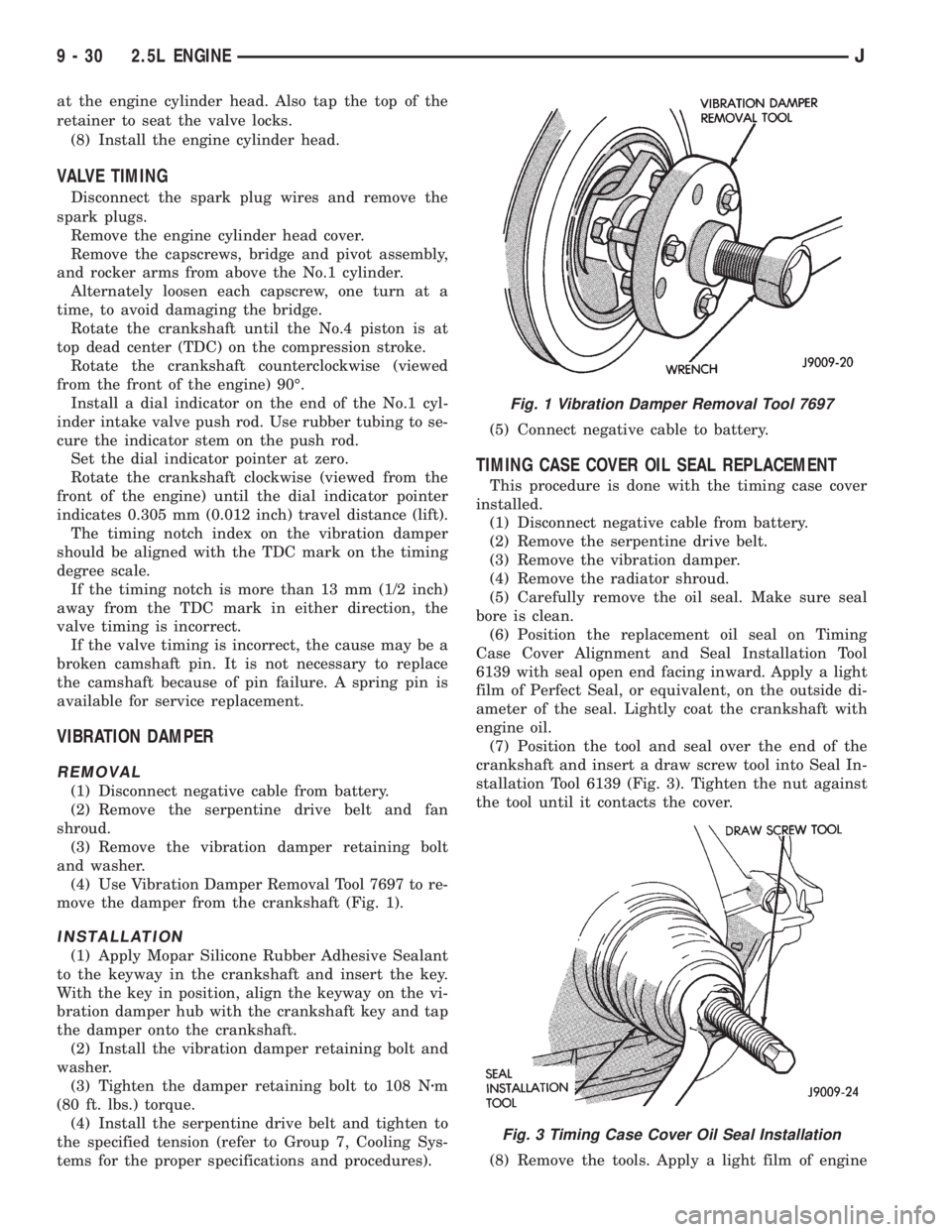
(4) Use Vibration Damper Removal Tool 7697 to re-
move the damper from the crankshaft (Fig. 1).
INSTALLATION
(1) Apply Mopar Silicone Rubber Adhesive Sealant
to the keyway in the crankshaft and insert the key.
With the key in position, align the keyway on the vi-
bration damper hub with the crankshaft key and tap
the damper onto the crankshaft.
(2) Install the vibration damper retaining bolt and
washer.
(3) Tighten the damper retaining bolt to 108 Nzm
(80 ft. lbs.) torque.
(4) Install the serpentine drive belt and tighten to
the specified tension (refer to Group 7, Cooling Sys-
tems for the proper specifications and procedures).(5) Connect negative cable to battery.
TIMING CASE COVER OIL SEAL REPLACEMENT
This procedure is done with the timing case cover
installed.
(1) Disconnect negative cable from battery.
(2) Remove the serpentine drive belt.
(3) Remove the vibration damper.
(4) Remove the radiator shroud.
(5) Carefully remove the oil seal. Make sure seal
bore is clean.
(6) Position the replacement oil seal on Timing
Case Cover Alignment and Seal Installation Tool
6139 with seal open end facing inward. Apply a light
film of Perfect Seal, or equivalent, on the outside di-
ameter of the seal. Lightly coat the crankshaft with
engine oil.
(7) Position the tool and seal over the end of the
crankshaft and insert a draw screw tool into Seal In-
stallation Tool 6139 (Fig. 3). Tighten the nut against
the tool until it contacts the cover.
(8) Remove the tools. Apply a light film of engine
Fig. 1 Vibration Damper Removal Tool 7697
Fig. 3 Timing Case Cover Oil Seal Installation
9 - 30 2.5L ENGINEJ
Page 1324 of 2158
CAUTION: Verify that the oil squirt holes in the rods
face the camshaft and that the arrows on the pis-
tons face the front of the engine.
(7) Install the oil pan and gaskets as outlined in
the installation procedure.
(8) Lower the vehicle.
(9) Install the engine cylinder head, push rods,
rocker arms, bridges, pivots and engine cylinder head
cover.
(10) Fill the crankcase with engine oil.
CRANKSHAFT MAIN BEARINGS
REMOVAL
(1) Disconnect negative cable from battery.
(2) Remove the spark plugs.
(3) Raise the vehicle.
(4) Remove the oil pan and oil pump.
(5) Remove only one main bearing cap and lower
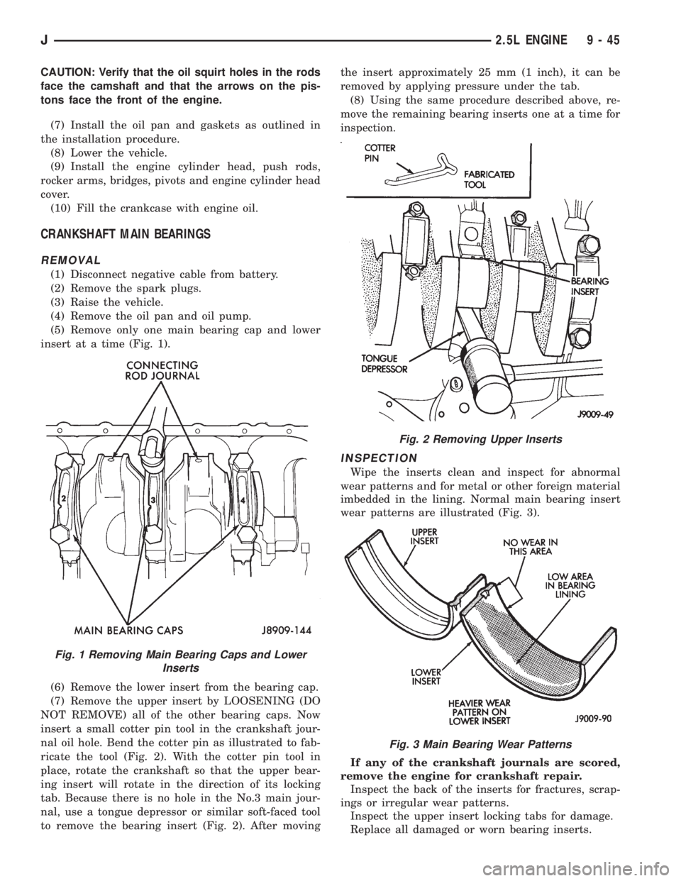
insert at a time (Fig. 1).
(6) Remove the lower insert from the bearing cap.
(7) Remove the upper insert by LOOSENING (DO
NOT REMOVE) all of the other bearing caps. Now
insert a small cotter pin tool in the crankshaft jour-
nal oil hole. Bend the cotter pin as illustrated to fab-
ricate the tool (Fig. 2). With the cotter pin tool in
place, rotate the crankshaft so that the upper bear-
ing insert will rotate in the direction of its locking
tab. Because there is no hole in the No.3 main jour-
nal, use a tongue depressor or similar soft-faced tool
to remove the bearing insert (Fig. 2). After movingthe insert approximately 25 mm (1 inch), it can be
removed by applying pressure under the tab.
(8) Using the same procedure described above, re-
move the remaining bearing inserts one at a time for
inspection.
INSPECTION
Wipe the inserts clean and inspect for abnormal
wear patterns and for metal or other foreign material
imbedded in the lining. Normal main bearing insert
wear patterns are illustrated (Fig. 3).
If any of the crankshaft journals are scored,
remove the engine for crankshaft repair.
Inspect the back of the inserts for fractures, scrap-
ings or irregular wear patterns.
Inspect the upper insert locking tabs for damage.
Replace all damaged or worn bearing inserts.
Fig. 1 Removing Main Bearing Caps and Lower
Inserts
Fig. 2 Removing Upper Inserts
Fig. 3 Main Bearing Wear Patterns
J2.5L ENGINE 9 - 45
Page 1328 of 2158
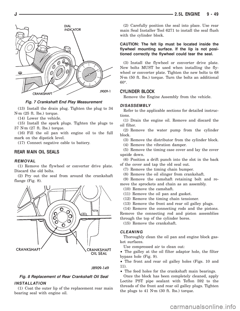
(13) Install the drain plug. Tighten the plug to 34
Nzm (25 ft. lbs.) torque.
(14) Lower the vehicle.
(15) Install the spark plugs. Tighten the plugs to
37 Nzm (27 ft. lbs.) torque.
(16) Fill the oil pan with engine oil to the full
mark on the dipstick level.
(17) Connect negative cable to battery.
REAR MAIN OIL SEALS
REMOVAL
(1) Remove the flywheel or converter drive plate.
Discard the old bolts.
(2) Pry out the seal from around the crankshaft
flange (Fig. 8).
INSTALLATION
(1) Coat the outer lip of the replacement rear main
bearing seal with engine oil.(2) Carefully position the seal into place. Use rear
main Seal Installer Tool 6271 to install the seal flush
with the cylinder block.
CAUTION: The felt lip must be located inside the
flywheel mounting surface. If the lip is not posi-
tioned correctly the flywheel could tear the seal.
(3) Install the flywheel or converter drive plate.
New bolts MUST be used when installing the fly-
wheel or converter plate. Tighten the new bolts to 68
Nzm (50 ft. lbs.) torque. Turn the bolts an additional
60É.
CYLINDER BLOCK
Remove the Engine Assembly from the vehicle.
DISASSEMBLY
Refer to the applicable sections for detailed instruc-
tions.
(1) Drain the engine oil. Remove and discard the
oil filter.
(2) Remove the water pump from the cylinder
block.
(3) Remove the distributor from the cylinder block.
(4) Remove the vibration damper.
(5) Remove the timing case cover and lay the cover
upside down.
(6) Position a drift punch into the slot in the back
of the cover and tap the old seal out.
(7) Remove the timing chain bumper.
(8) Remove the oil slinger from crankshaft.
(9) Remove the camshaft retaining bolt and re-
move the sprockets and chain as an assembly.
(10) Remove the camshaft.
(11) Remove the oil pan and gasket.
(12) Remove the timing chain tensioner.
(13) Remove the front and rear oil galley plugs.
(14) Remove the connecting rods and the pistons.
Remove the connecting rod and piston assemblies
through the top of the cylinder bores.
(15) Remove the crankshaft.
CLEANING
Thoroughly clean the oil pan and engine block gas-
ket surfaces.
Use compressed air to clean out:
²The galley at the oil filter adaptor hole, the filter
bypass hole (Fig. 9).
²The front and rear oil galley holes (Figs. 10 and
11).
²The feed holes for the crankshaft main bearings.
Once the block has been completely cleaned, apply
Loctite PST pipe sealant with Teflon 592 to the
threads of the front and rear oil galley plugs. Tighten
the plugs to 41 Nzm (30 ft. lbs.) torque.
Fig. 7 Crankshaft End Play Measurement
Fig. 8 Replacement of Rear Crankshaft Oil Seal
J2.5L ENGINE 9 - 49