JEEP YJ 1995 Service And Repair Manual
Manufacturer: JEEP, Model Year: 1995, Model line: YJ, Model: JEEP YJ 1995Pages: 2158, PDF Size: 81.9 MB
Page 211 of 2158
If the brake drums are heavily coated with rust,
clean and inspect them carefully. Rust damage on
high mileage drums can be severe enough to require
replacement.
New drums have a protective coating that should
be removed before installation.It is not necessary
to machine a drum to remove this coating. The
coating is easily removed with Mopar carb
cleaner followed by a rinse with Mopar brake
cleaner. A scotch brite pad, or steel wool can
also be used to help loosen and remove the
coating if desired.
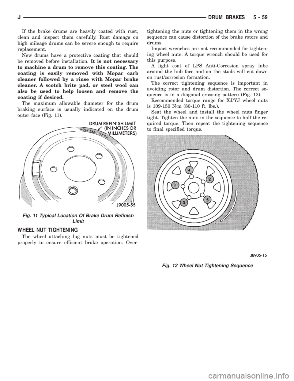
The maximum allowable diameter for the drum
braking surface is usually indicated on the drum
outer face (Fig. 11).
WHEEL NUT TIGHTENING
The wheel attaching lug nuts must be tightened
properly to ensure efficient brake operation. Over-tightening the nuts or tightening them in the wrong
sequence can cause distortion of the brake rotors and
drums.
Impact wrenches are not recommended for tighten-
ing wheel nuts. A torque wrench should be used for
this purpose.
A light coat of LPS Anti-Corrosion spray lube
around the hub face and on the studs will cut down
on rust/corrosion formation.
The correct tightening sequence is important in
avoiding rotor and drum distortion. The correct se-
quence is in a diagonal crossing pattern (Fig. 12).
Recommended torque range for XJ/YJ wheel nuts
is 109-150 Nzm (80-110 ft. lbs.).
Seat the wheel and install the wheel nuts finger
tight. Tighten the nuts in the sequence to half the re-
quired torque. Then repeat the tightening sequence
to final specified torque.
Fig. 11 Typical Location Of Brake Drum Refinish
Limit
Fig. 12 Wheel Nut Tightening Sequence
JDRUM BRAKES 5 - 59
Page 212 of 2158
PARKING BRAKES
INDEX
page page
General Service Information................. 60
Parking Brake Cable Tensioner Adjustment (XJ/YJ).. 68
Parking Brake Cable Tensioner Replacement (XJ) . 65
Parking Brake Front Cable Replacement (YJ).... 67
Parking Brake Lever Installation (XJ with Full
Console).............................. 64
Parking Brake Lever Installation (XJ with Mini
Console).............................. 63
Parking Brake Lever Installation (XJ Without
Console).............................. 65Parking Brake Lever Removal (XJ with Full Console).63
Parking Brake Lever Removal (XJ with Mini
Console).............................. 62
Parking Brake Lever Removal (XJ Without Console).64
Parking Brake Operation.................... 60
Parking Brake Pedal Installation (YJ)........... 66
Parking Brake Pedal Removal (YJ)............ 66
Parking Brake Rear Cable Replacement (XJ)..... 66
Parking Brake Rear Cable Replacement (YJ)..... 68
Parking Brake Switch...................... 68
GENERAL SERVICE INFORMATION
Parking brake adjustment is controlled by a cable ten-
sioner mechanism.
The cable tensioner, once adjusted at the factory,
should not need further adjustment under normal
circumstances. There are only two instances when
adjustment is required. The first is when a new ten-
sioner, or cables have been installed. And the second,
is when the tensioner and cables are disconnected for
access to other brake components.
PARKING BRAKE OPERATION
The rear brakes are utilized for the parking brake
function. They are actuated hydraulically during nor-
mal brake operation but are mechanically actuated
for parking brake operation.
Parking Brake Components
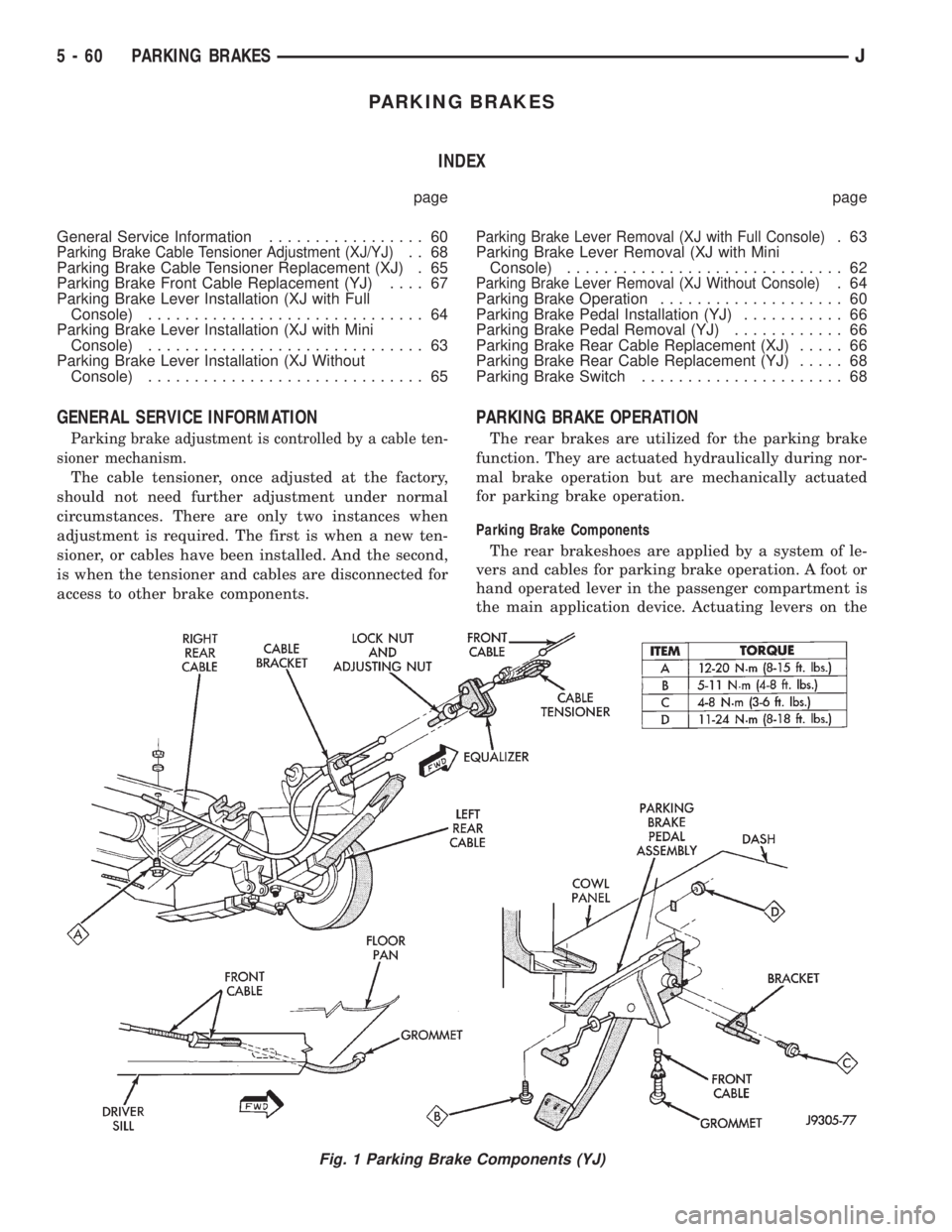
The rear brakeshoes are applied by a system of le-
vers and cables for parking brake operation. A foot or
hand operated lever in the passenger compartment is
the main application device. Actuating levers on the
Fig. 1 Parking Brake Components (YJ)
5 - 60 PARKING BRAKESJ
Page 213 of 2158
secondary brakeshoes move the shoes directly into
contact with the drum braking surface. The actuating
levers are interconnected by a system of cables and a
tensioner mechanism. The tensioner mechanism con-
trols parking brake adjustment.
A parking brake switch is used on all models. It is
mounted on the parking brake lever or foot pedal and
is actuated by movement of the lever/pedal. The
switch, which is in circuit with the red warning light
in the dash, will illuminate the warning light when-
ever the parking brakes are applied.
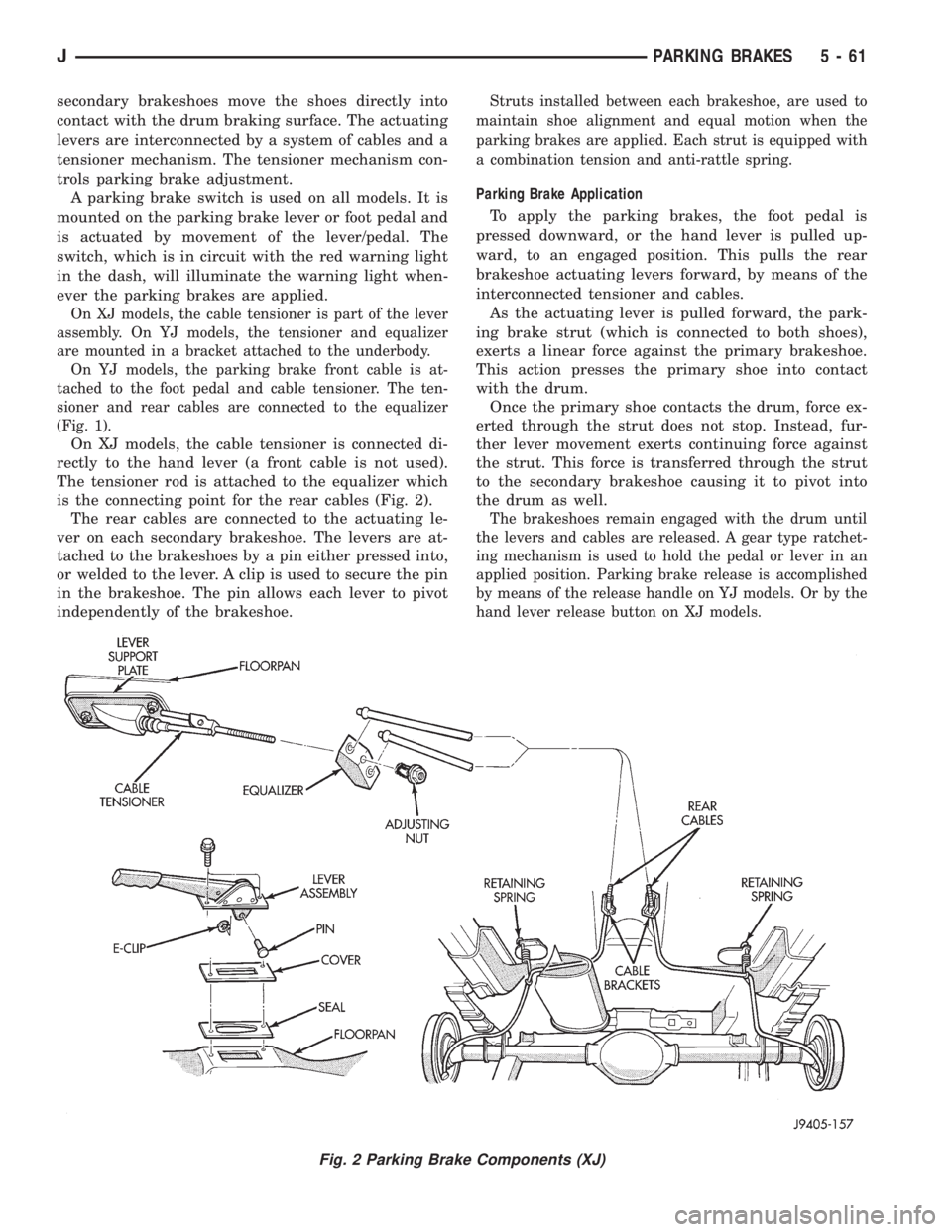
On XJ models, the cable tensioner is part of the lever
assembly. On YJ models, the tensioner and equalizer
are mounted in a bracket attached to the underbody.
On YJ models, the parking brake front cable is at-
tached to the foot pedal and cable tensioner. The ten-
sioner and rear cables are connected to the equalizer
(Fig. 1).
On XJ models, the cable tensioner is connected di-
rectly to the hand lever (a front cable is not used).
The tensioner rod is attached to the equalizer which
is the connecting point for the rear cables (Fig. 2).
The rear cables are connected to the actuating le-
ver on each secondary brakeshoe. The levers are at-
tached to the brakeshoes by a pin either pressed into,
or welded to the lever. A clip is used to secure the pin
in the brakeshoe. The pin allows each lever to pivot
independently of the brakeshoe.
Struts installed between each brakeshoe, are used to
maintain shoe alignment and equal motion when the
parking brakes are applied. Each strut is equipped with
a combination tension and anti-rattle spring.
Parking Brake Application
To apply the parking brakes, the foot pedal is
pressed downward, or the hand lever is pulled up-
ward, to an engaged position. This pulls the rear
brakeshoe actuating levers forward, by means of the
interconnected tensioner and cables.
As the actuating lever is pulled forward, the park-
ing brake strut (which is connected to both shoes),
exerts a linear force against the primary brakeshoe.
This action presses the primary shoe into contact
with the drum.
Once the primary shoe contacts the drum, force ex-
erted through the strut does not stop. Instead, fur-
ther lever movement exerts continuing force against
the strut. This force is transferred through the strut
to the secondary brakeshoe causing it to pivot into
the drum as well.
The brakeshoes remain engaged with the drum until
the levers and cables are released. A gear type ratchet-
ing mechanism is used to hold the pedal or lever in an
applied position. Parking brake release is accomplished
by means of the release handle on YJ models. Or by the
hand lever release button on XJ models.
Fig. 2 Parking Brake Components (XJ)
JPARKING BRAKES 5 - 61
Page 214 of 2158
PARKING BRAKE LEVER REMOVAL (XJ WITH MINI
CONSOLE)
(1) Release parking brakes, if necessary.
(2) Raise vehicle.
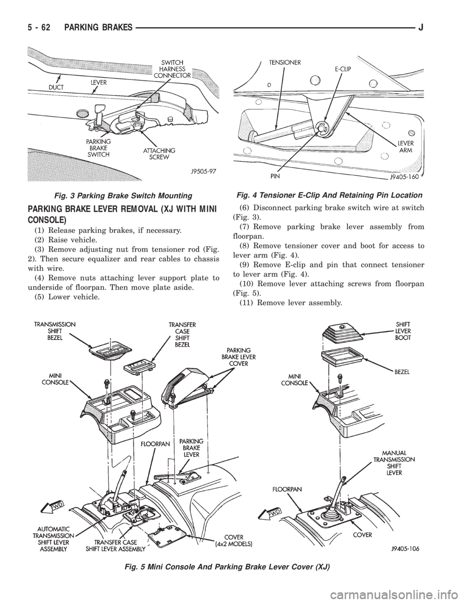
(3) Remove adjusting nut from tensioner rod (Fig.
2). Then secure equalizer and rear cables to chassis
with wire.
(4) Remove nuts attaching lever support plate to
underside of floorpan. Then move plate aside.
(5) Lower vehicle.(6) Disconnect parking brake switch wire at switch
(Fig. 3).
(7) Remove parking brake lever assembly from
floorpan.
(8) Remove tensioner cover and boot for access to
lever arm (Fig. 4).
(9) Remove E-clip and pin that connect tensioner
to lever arm (Fig. 4).
(10) Remove lever attaching screws from floorpan
(Fig. 5).
(11) Remove lever assembly.
Fig. 3 Parking Brake Switch MountingFig. 4 Tensioner E-Clip And Retaining Pin Location
Fig. 5 Mini Console And Parking Brake Lever Cover (XJ)
5 - 62 PARKING BRAKESJ
Page 215 of 2158
(12) Parking brake switch can be serviced at this
time, if necessary.
PARKING BRAKE LEVER INSTALLATION (XJ WITH
MINI CONSOLE)
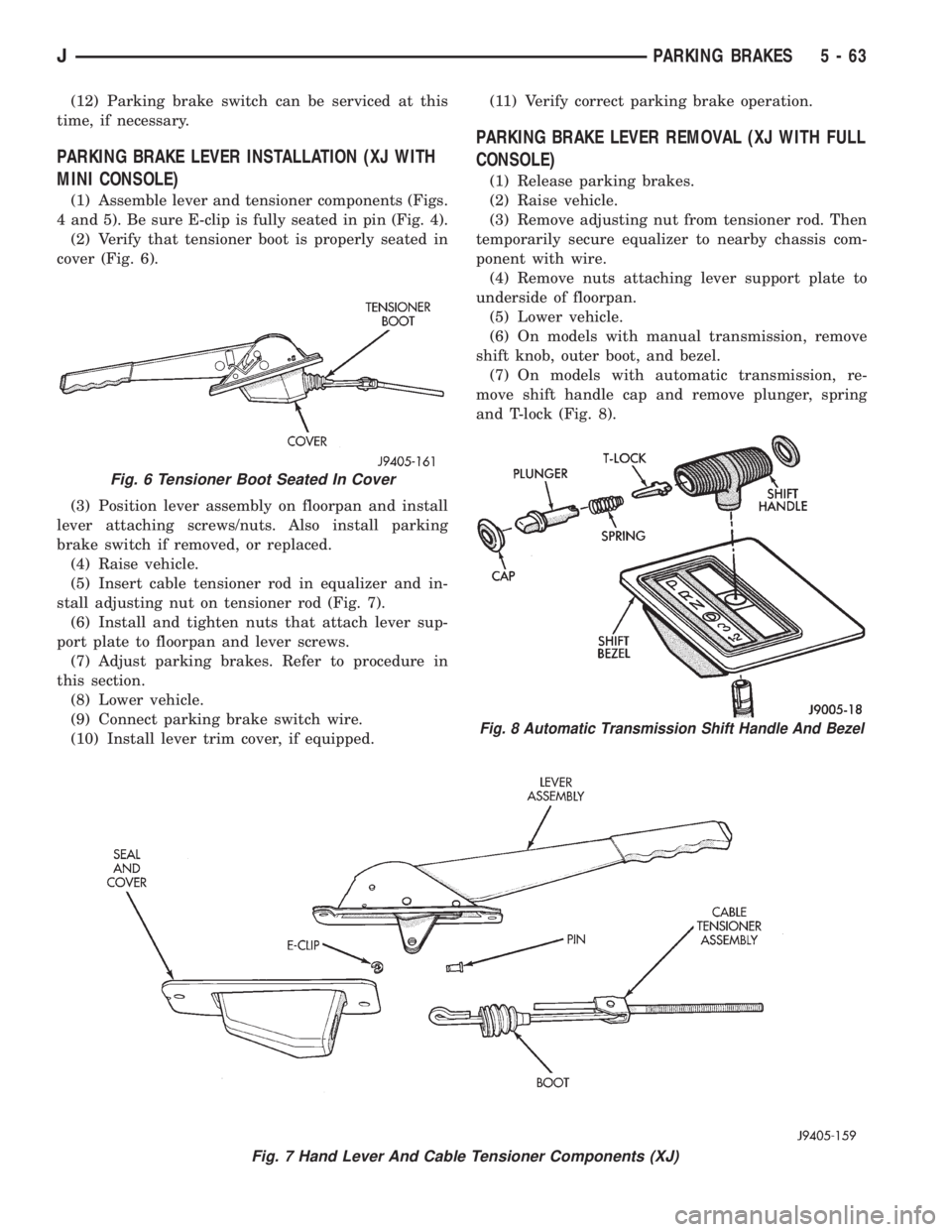
(1) Assemble lever and tensioner components (Figs.
4 and 5). Be sure E-clip is fully seated in pin (Fig. 4).
(2) Verify that tensioner boot is properly seated in
cover (Fig. 6).
(3) Position lever assembly on floorpan and install
lever attaching screws/nuts. Also install parking
brake switch if removed, or replaced.
(4) Raise vehicle.
(5) Insert cable tensioner rod in equalizer and in-
stall adjusting nut on tensioner rod (Fig. 7).
(6) Install and tighten nuts that attach lever sup-
port plate to floorpan and lever screws.
(7) Adjust parking brakes. Refer to procedure in
this section.
(8) Lower vehicle.
(9) Connect parking brake switch wire.
(10) Install lever trim cover, if equipped.(11) Verify correct parking brake operation.
PARKING BRAKE LEVER REMOVAL (XJ WITH FULL
CONSOLE)
(1) Release parking brakes.
(2) Raise vehicle.
(3) Remove adjusting nut from tensioner rod. Then
temporarily secure equalizer to nearby chassis com-
ponent with wire.
(4) Remove nuts attaching lever support plate to
underside of floorpan.
(5) Lower vehicle.
(6) On models with manual transmission, remove
shift knob, outer boot, and bezel.
(7) On models with automatic transmission, re-
move shift handle cap and remove plunger, spring
and T-lock (Fig. 8).
Fig. 7 Hand Lever And Cable Tensioner Components (XJ)
Fig. 6 Tensioner Boot Seated In Cover
Fig. 8 Automatic Transmission Shift Handle And Bezel
JPARKING BRAKES 5 - 63
Page 216 of 2158
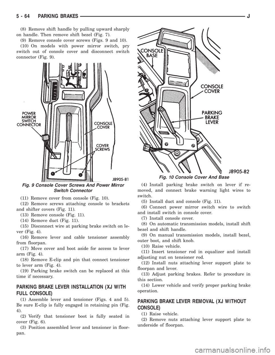
(8) Remove shift handle by pulling upward sharply
on handle. Then remove shift bezel (Fig. 7).
(9) Remove console cover screws (Figs. 9 and 10).
(10) On models with power mirror switch, pry
switch out of console cover and disconnect switch
connector (Fig. 9).
(11) Remove cover from console (Fig. 10).
(12) Remove screws attaching console to brackets
and shifter covers (Fig. 11).
(13) Remove console (Fig. 11).
(14) Remove duct (Fig. 11).
(15) Disconnect wire at parking brake switch on le-
ver (Fig. 4).
(16) Remove lever and cable tensioner assembly
from floorpan.
(17) Move cover and boot aside for access to lever
arm (Fig. 4).
(18) Remove E-clip and pin that connect tensioner
to lever arm (Fig. 4).
(19) Parking brake switch can be replaced at this
time if necessary.
PARKING BRAKE LEVER INSTALLATION (XJ WITH
FULL CONSOLE)
(1) Assemble lever and tensioner (Figs. 4 and 5).
Be sure E-clip is fully engaged in retaining pin (Fig.
4).
(2) Verify that tensioner boot is fully seated in
cover (Fig. 6).
(3) Position assembled lever and tensioner in floor-
pan.(4) Install parking brake switch on lever if re-
moved, and connect brake warning light wires to
switch.
(5) Install duct and console (Fig. 11).
(6) Connect power mirror switch wire to switch
and install switch in console cover.
(7) Install console cover.
(8) On automatic transmission models, install shift
bezel and shift handle.
(9) On manual transmission models, install bezel,
outer boot, and shift knob.
(10) Raise vehicle.
(11) Insert tensioner rod in equalizer and install
adjusting nut on tensioner rod.
(12) Install nuts attaching lever support plate to
floorpan and lever.
(13) Adjust parking brakes. Refer to procedure in
this section.
(14) Lower vehicle and verify proper parking brake
operation.PARKING BRAKE LEVER REMOVAL (XJ WITHOUT
CONSOLE)
(1) Raise vehicle.
(2) Remove nuts attaching lever support plate to
underside of floorpan.
Fig. 9 Console Cover Screws And Power Mirror
Switch Connector
Fig. 10 Console Cover And Base
5 - 64 PARKING BRAKESJ
Page 217 of 2158
(3) Remove adjusting nut from tensioner rod. Then
temporarily secure equalizer and cables to nearby
chassis component with wire.
(4) Lower vehicle.
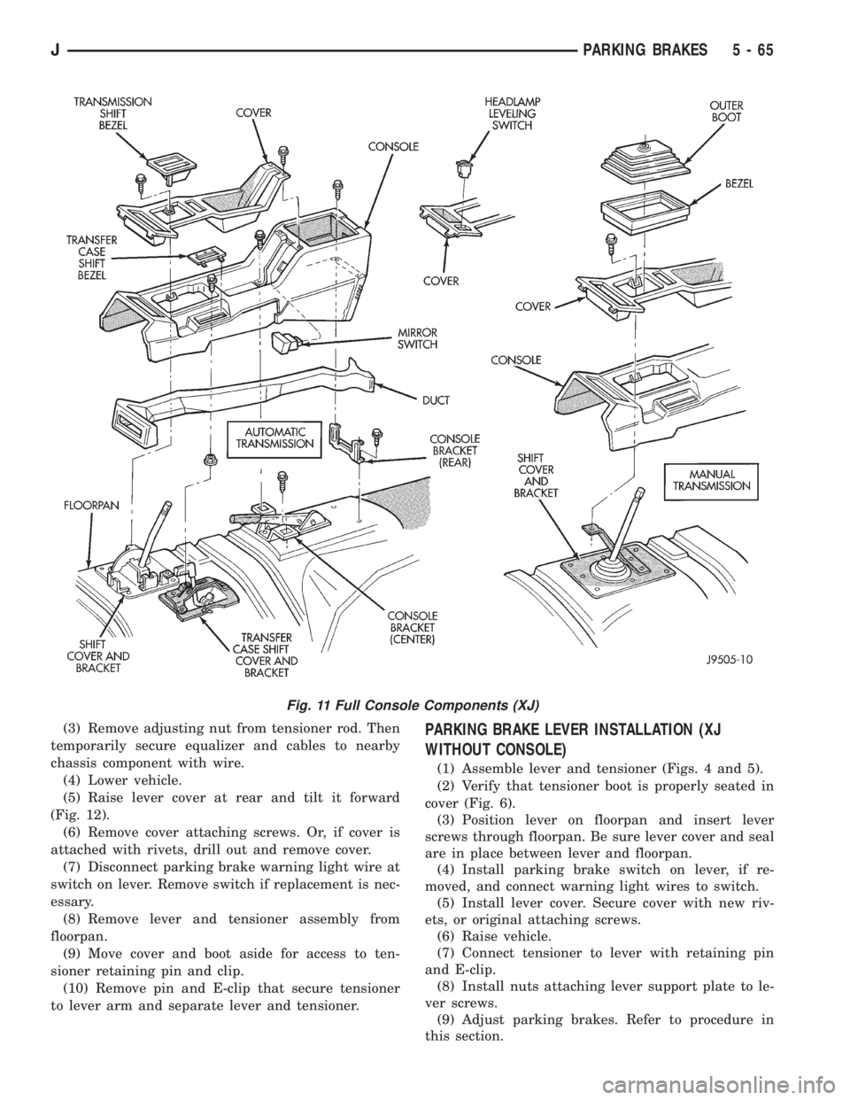
(5) Raise lever cover at rear and tilt it forward
(Fig. 12).
(6) Remove cover attaching screws. Or, if cover is
attached with rivets, drill out and remove cover.
(7) Disconnect parking brake warning light wire at
switch on lever. Remove switch if replacement is nec-
essary.
(8) Remove lever and tensioner assembly from
floorpan.
(9) Move cover and boot aside for access to ten-
sioner retaining pin and clip.
(10) Remove pin and E-clip that secure tensioner
to lever arm and separate lever and tensioner.PARKING BRAKE LEVER INSTALLATION (XJ
WITHOUT CONSOLE)
(1) Assemble lever and tensioner (Figs. 4 and 5).
(2) Verify that tensioner boot is properly seated in
cover (Fig. 6).
(3) Position lever on floorpan and insert lever
screws through floorpan. Be sure lever cover and seal
are in place between lever and floorpan.
(4) Install parking brake switch on lever, if re-
moved, and connect warning light wires to switch.
(5) Install lever cover. Secure cover with new riv-
ets, or original attaching screws.
(6) Raise vehicle.
(7) Connect tensioner to lever with retaining pin
and E-clip.
(8) Install nuts attaching lever support plate to le-
ver screws.
(9) Adjust parking brakes. Refer to procedure in
this section.
Fig. 11 Full Console Components (XJ)
JPARKING BRAKES 5 - 65
Page 218 of 2158
PARKING BRAKE CABLE TENSIONER
REPLACEMENT (XJ)
(1) Raise vehicle.
(2) Remove adjuster nut from tensioner rod. Secure
equalizer and cables to nearby chassis component
with wire.
(3) Remove nuts attaching lever assembly to sup-
port plate and floorpan.
(4) Lower vehicle.
(5) Remove console components and lever assembly
cover.
(6) Remove lever and tensioner assembly.
(7) Move cover and boot for access to tensioner re-
taining pin.
(8) Remove E-clip and pin that attach tensioner to
lever arm (Fig. 4).
(9) Remove tensioner from cover.
(10) Transfer boot to new tensioner if necessary.
(11) Attach tensioner to lever arm with pin and E-
clip.
(12) Verify that E-clip is fully engaged in pin (Fig.
4).
(13) Align cover and seal on lever flange.
(14) Verify that tensioner boot is seated in cover
(Fig. 6).
(15) Install assembled lever and tensioner in floor-
pan.
(16) Install necessary console components.
(17) Adjust parking brakes as described in this sec-
tion.
PARKING BRAKE PEDAL REMOVAL (YJ)
(1) Raise vehicle.
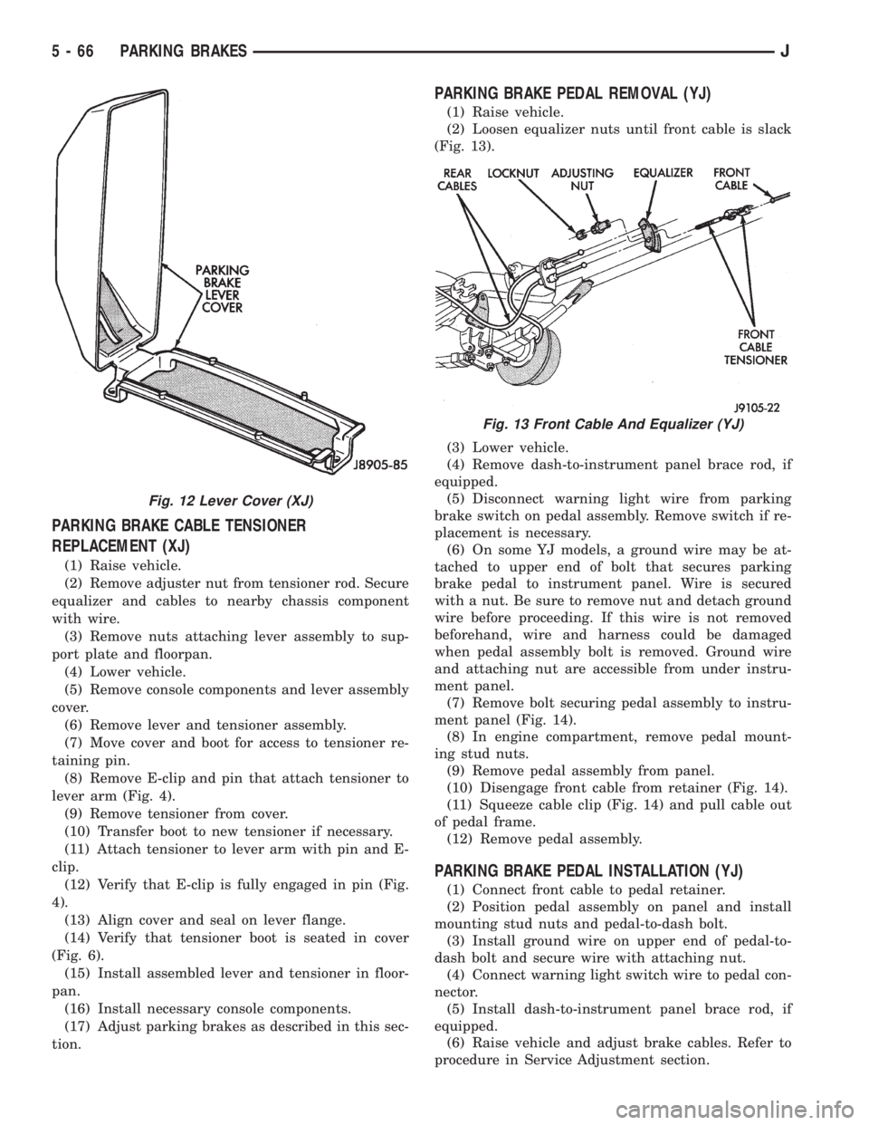
(2) Loosen equalizer nuts until front cable is slack
(Fig. 13).
(3) Lower vehicle.
(4) Remove dash-to-instrument panel brace rod, if
equipped.
(5) Disconnect warning light wire from parking
brake switch on pedal assembly. Remove switch if re-
placement is necessary.
(6) On some YJ models, a ground wire may be at-
tached to upper end of bolt that secures parking
brake pedal to instrument panel. Wire is secured
with a nut. Be sure to remove nut and detach ground
wire before proceeding. If this wire is not removed
beforehand, wire and harness could be damaged
when pedal assembly bolt is removed. Ground wire
and attaching nut are accessible from under instru-
ment panel.
(7) Remove bolt securing pedal assembly to instru-
ment panel (Fig. 14).
(8) In engine compartment, remove pedal mount-
ing stud nuts.
(9) Remove pedal assembly from panel.
(10) Disengage front cable from retainer (Fig. 14).
(11) Squeeze cable clip (Fig. 14) and pull cable out
of pedal frame.
(12) Remove pedal assembly.
PARKING BRAKE PEDAL INSTALLATION (YJ)
(1) Connect front cable to pedal retainer.
(2) Position pedal assembly on panel and install
mounting stud nuts and pedal-to-dash bolt.
(3) Install ground wire on upper end of pedal-to-
dash bolt and secure wire with attaching nut.
(4) Connect warning light switch wire to pedal con-
nector.
(5) Install dash-to-instrument panel brace rod, if
equipped.
(6) Raise vehicle and adjust brake cables. Refer to
procedure in Service Adjustment section.
Fig. 12 Lever Cover (XJ)
Fig. 13 Front Cable And Equalizer (YJ)
5 - 66 PARKING BRAKESJ
Page 219 of 2158
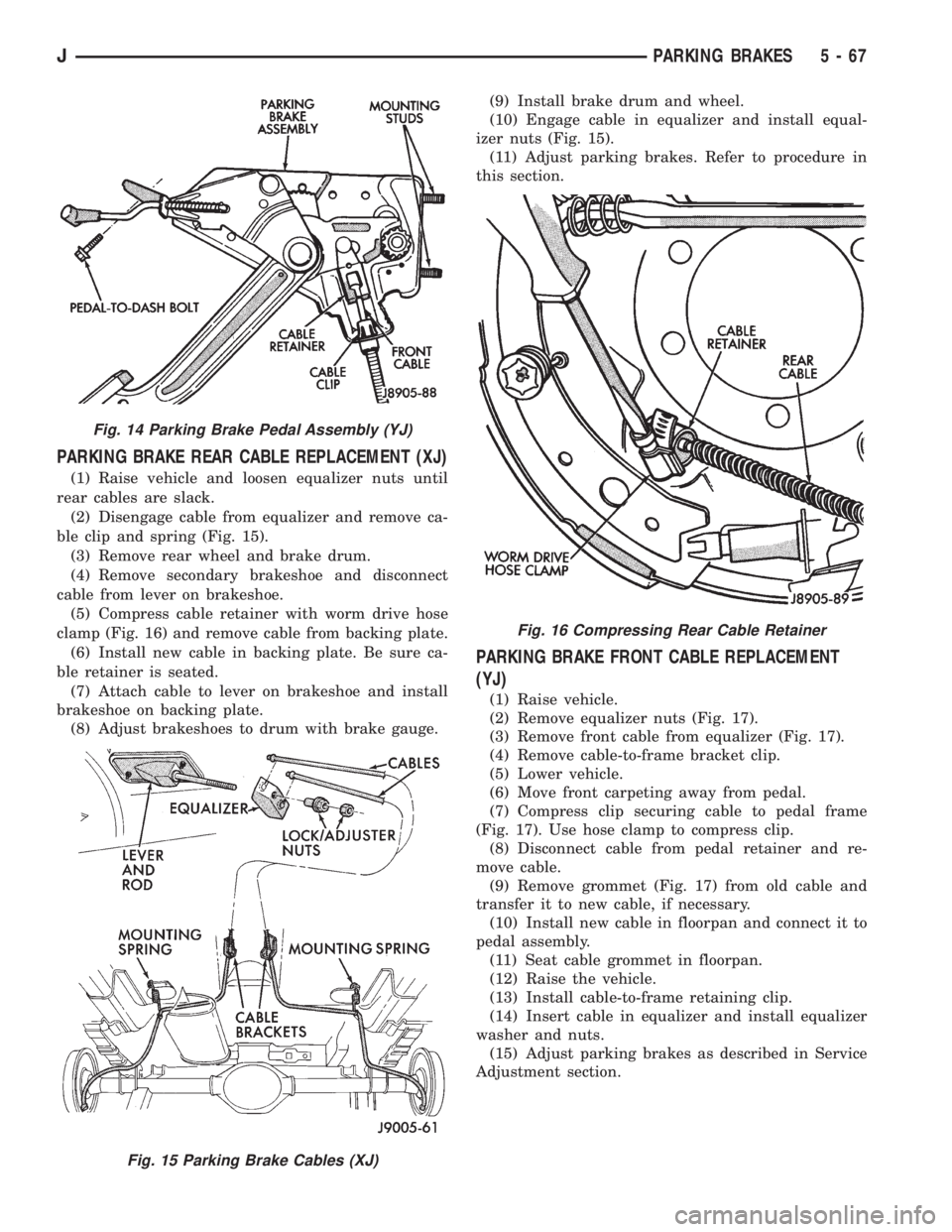
PARKING BRAKE REAR CABLE REPLACEMENT (XJ)
(1) Raise vehicle and loosen equalizer nuts until
rear cables are slack.
(2) Disengage cable from equalizer and remove ca-
ble clip and spring (Fig. 15).
(3) Remove rear wheel and brake drum.
(4) Remove secondary brakeshoe and disconnect
cable from lever on brakeshoe.
(5) Compress cable retainer with worm drive hose
clamp (Fig. 16) and remove cable from backing plate.
(6) Install new cable in backing plate. Be sure ca-
ble retainer is seated.
(7) Attach cable to lever on brakeshoe and install
brakeshoe on backing plate.
(8) Adjust brakeshoes to drum with brake gauge.(9) Install brake drum and wheel.
(10) Engage cable in equalizer and install equal-
izer nuts (Fig. 15).
(11) Adjust parking brakes. Refer to procedure in
this section.
PARKING BRAKE FRONT CABLE REPLACEMENT
(YJ)
(1) Raise vehicle.
(2) Remove equalizer nuts (Fig. 17).
(3) Remove front cable from equalizer (Fig. 17).
(4) Remove cable-to-frame bracket clip.
(5) Lower vehicle.
(6) Move front carpeting away from pedal.
(7) Compress clip securing cable to pedal frame
(Fig. 17). Use hose clamp to compress clip.
(8) Disconnect cable from pedal retainer and re-
move cable.
(9) Remove grommet (Fig. 17) from old cable and
transfer it to new cable, if necessary.
(10) Install new cable in floorpan and connect it to
pedal assembly.
(11) Seat cable grommet in floorpan.
(12) Raise the vehicle.
(13) Install cable-to-frame retaining clip.
(14) Insert cable in equalizer and install equalizer
washer and nuts.
(15) Adjust parking brakes as described in Service
Adjustment section.
Fig. 14 Parking Brake Pedal Assembly (YJ)
Fig. 15 Parking Brake Cables (XJ)
Fig. 16 Compressing Rear Cable Retainer
JPARKING BRAKES 5 - 67
Page 220 of 2158
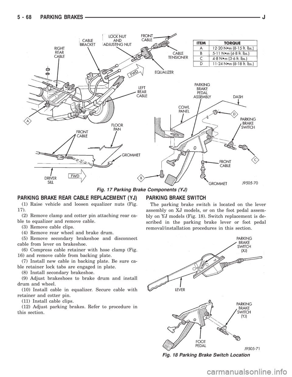
PARKING BRAKE REAR CABLE REPLACEMENT (YJ)
(1) Raise vehicle and loosen equalizer nuts (Fig.
17).
(2) Remove clamp and cotter pin attaching rear ca-
ble to equalizer and remove cable.
(3) Remove cable clips.
(4) Remove rear wheel and brake drum.
(5) Remove secondary brakeshoe and disconnect
cable from lever on brakeshoe.
(6) Compress cable retainer with hose clamp (Fig.
16) and remove cable from backing plate.
(7) Install new cable in backing plate. Be sure ca-
ble retainer lock tabs are engaged in plate.
(8) Install secondary brakeshoe.
(9) Adjust brakeshoes to brake drum and install
drum and wheel.
(10) Install cable in equalizer. Secure cable with
retainer and cotter pin.
(11) Install cable clips.
(12) Adjust parking brakes. Refer to procedure in
this section.
PARKING BRAKE SWITCH
The parking brake switch is located on the lever
assembly on XJ models, or on the foot pedal assem-
bly on YJ models (Fig. 18). Switch replacement is de-
scribed in the parking brake lever or foot pedal
removal/installation procedures in this section.
Fig. 17 Parking Brake Components (YJ)
Fig. 18 Parking Brake Switch Location
5 - 68 PARKING BRAKESJ