relay JEEP YJ 1995 Service And Owner's Manual
[x] Cancel search | Manufacturer: JEEP, Model Year: 1995, Model line: YJ, Model: JEEP YJ 1995Pages: 2158, PDF Size: 81.9 MB
Page 401 of 2158
AUDIO SYSTEMS
CONTENTS
page page
DIAGNOSIS............................. 2
GENERAL INFORMATION.................. 1SERVICE PROCEDURES................... 6
GENERAL INFORMATION
Following are general descriptions of major compo-
nents used in XJ (Cherokee)/YJ (Wrangler) audio sys-
tems. Refer to Group 8W - Wiring Diagrams for
complete circuit descriptions and diagrams.
RADIOS
Radio options for the XJ and YJ models include an
AM/FM stereo or an AM/FM stereo/cassette receiver.
Both units are Electronically-Tuned Radios (ETR)
and include a clock function. For more information
on radio features, setting procedures, and control
functions refer to the owner's manual.
IN-LINE FUSE
Each radio receives fused battery feed when the ig-
nition switch is in the ON or ACCESSORY position.
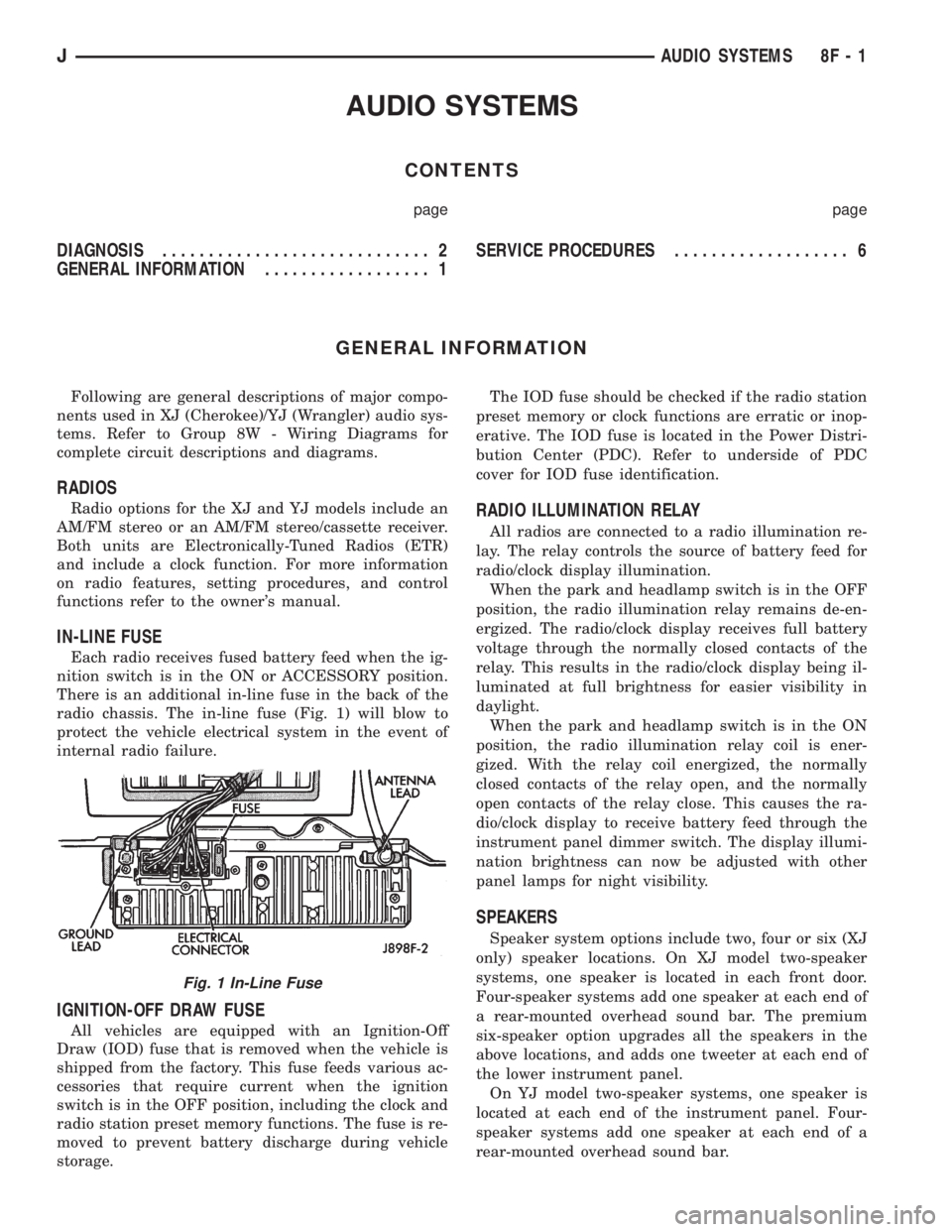
There is an additional in-line fuse in the back of the
radio chassis. The in-line fuse (Fig. 1) will blow to
protect the vehicle electrical system in the event of
internal radio failure.
IGNITION-OFF DRAW FUSE
All vehicles are equipped with an Ignition-Off
Draw (IOD) fuse that is removed when the vehicle is
shipped from the factory. This fuse feeds various ac-
cessories that require current when the ignition
switch is in the OFF position, including the clock and
radio station preset memory functions. The fuse is re-
moved to prevent battery discharge during vehicle
storage.The IOD fuse should be checked if the radio station
preset memory or clock functions are erratic or inop-
erative. The IOD fuse is located in the Power Distri-
bution Center (PDC). Refer to underside of PDC
cover for IOD fuse identification.
RADIO ILLUMINATION RELAY
All radios are connected to a radio illumination re-
lay. The relay controls the source of battery feed for
radio/clock display illumination.
When the park and headlamp switch is in the OFF
position, the radio illumination relay remains de-en-
ergized. The radio/clock display receives full battery
voltage through the normally closed contacts of the
relay. This results in the radio/clock display being il-
luminated at full brightness for easier visibility in
daylight.
When the park and headlamp switch is in the ON
position, the radio illumination relay coil is ener-
gized. With the relay coil energized, the normally
closed contacts of the relay open, and the normally
open contacts of the relay close. This causes the ra-
dio/clock display to receive battery feed through the
instrument panel dimmer switch. The display illumi-
nation brightness can now be adjusted with other
panel lamps for night visibility.
SPEAKERS
Speaker system options include two, four or six (XJ
only) speaker locations. On XJ model two-speaker
systems, one speaker is located in each front door.
Four-speaker systems add one speaker at each end of
a rear-mounted overhead sound bar. The premium
six-speaker option upgrades all the speakers in the
above locations, and adds one tweeter at each end of
the lower instrument panel.
On YJ model two-speaker systems, one speaker is
located at each end of the instrument panel. Four-
speaker systems add one speaker at each end of a
rear-mounted overhead sound bar.
Fig. 1 In-Line Fuse
JAUDIO SYSTEMS 8F - 1
Page 404 of 2158
RADIO ILLUMINATION RELAY
If the relay fails any one of Relay Tests, it is faulty
and should be replaced. If the relay passes the Relay
Tests, proceed to the Relay Circuit Tests.
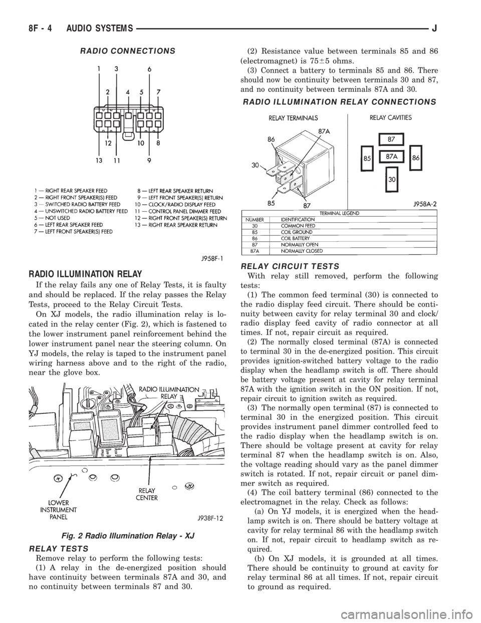
On XJ models, the radio illumination relay is lo-
cated in the relay center (Fig. 2), which is fastened to
the lower instrument panel reinforcement behind the
lower instrument panel near the steering column. On
YJ models, the relay is taped to the instrument panel
wiring harness above and to the right of the radio,
near the glove box.
RELAY TESTS
Remove relay to perform the following tests:
(1) A relay in the de-energized position should
have continuity between terminals 87A and 30, and
no continuity between terminals 87 and 30.(2) Resistance value between terminals 85 and 86
(electromagnet) is 7565 ohms.
(3) Connect a battery to terminals 85 and 86. There
should now be continuity between terminals 30 and 87,
and no continuity between terminals 87A and 30.
RELAY CIRCUIT TESTS
With relay still removed, perform the following
tests:
(1) The common feed terminal (30) is connected to
the radio display feed circuit. There should be conti-
nuity between cavity for relay terminal 30 and clock/
radio display feed cavity of radio connector at all
times. If not, repair circuit as required.
(2) The normally closed terminal (87A) is connected
to terminal 30 in the de-energized position. This circuit
provides ignition-switched battery voltage to the radio
display when the headlamp switch is off. There should
be battery voltage present at cavity for relay terminal
87A with the ignition switch in the ON position. If not,
repair circuit to ignition switch as required.
(3) The normally open terminal (87) is connected to
terminal 30 in the energized position. This circuit
provides instrument panel dimmer controlled feed to
the radio display when the headlamp switch is on.
There should be voltage present at cavity for relay
terminal 87 when the headlamp switch is on. Also,
the voltage reading should vary as the panel dimmer
switch is rotated. If not, repair circuit or panel dim-
mer switch as required.
(4) The coil battery terminal (86) connected to the
electromagnet in the relay. Check as follows:
(a) On YJ models, it is energized when the head-
lamp switch is on. There should be battery voltage at
cavity for relay terminal 86 with the headlamp switch
on. If not, repair circuit to headlamp switch as re-
quired.
(b) On XJ models, it is grounded at all times.
There should be continuity to ground at cavity for
relay terminal 86 at all times. If not, repair circuit
to ground as required.
RADIO CONNECTIONS
Fig. 2 Radio Illumination Relay - XJ
RADIO ILLUMINATION RELAY CONNECTIONS
8F - 4 AUDIO SYSTEMSJ
Page 405 of 2158
(5) The coil ground terminal (85) is connected to
the electromagnet in the relay. Check as follows:
(a) On YJ models, it is grounded at all times.
There should be continuity to ground at cavity for
relay terminal 85 at all times. If not, repair circuit
to ground as required.
(b) On XJ models, it is energized when the head-
lamp switch is on. There should be battery voltage
at cavity for relay terminal 85 with the headlamp
switch on. If not, repair circuit to headlamp switch
as required.
ANTENNA
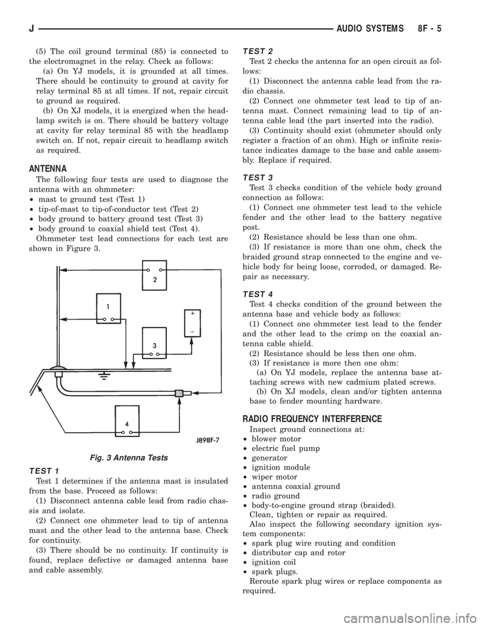
The following four tests are used to diagnose the
antenna with an ohmmeter:
²mast to ground test (Test 1)
²tip-of-mast to tip-of-conductor test (Test 2)
²body ground to battery ground test (Test 3)
²body ground to coaxial shield test (Test 4).
Ohmmeter test lead connections for each test are
shown in Figure 3.
TEST 1
Test 1 determines if the antenna mast is insulated
from the base. Proceed as follows:
(1) Disconnect antenna cable lead from radio chas-
sis and isolate.
(2) Connect one ohmmeter lead to tip of antenna
mast and the other lead to the antenna base. Check
for continuity.
(3) There should be no continuity. If continuity is
found, replace defective or damaged antenna base
and cable assembly.
TEST 2
Test 2 checks the antenna for an open circuit as fol-
lows:
(1) Disconnect the antenna cable lead from the ra-
dio chassis.
(2) Connect one ohmmeter test lead to tip of an-
tenna mast. Connect remaining lead to tip of an-
tenna cable lead (the part inserted into the radio).
(3) Continuity should exist (ohmmeter should only
register a fraction of an ohm). High or infinite resis-
tance indicates damage to the base and cable assem-
bly. Replace if required.
TEST 3
Test 3 checks condition of the vehicle body ground
connection as follows:
(1) Connect one ohmmeter test lead to the vehicle
fender and the other lead to the battery negative
post.
(2) Resistance should be less than one ohm.
(3) If resistance is more than one ohm, check the
braided ground strap connected to the engine and ve-
hicle body for being loose, corroded, or damaged. Re-
pair as necessary.
TEST 4
Test 4 checks condition of the ground between the
antenna base and vehicle body as follows:
(1) Connect one ohmmeter test lead to the fender
and the other lead to the crimp on the coaxial an-
tenna cable shield.
(2) Resistance should be less then one ohm.
(3) If resistance is more then one ohm:
(a) On YJ models, replace the antenna base at-
taching screws with new cadmium plated screws.
(b) On XJ models, clean and/or tighten antenna
base to fender mounting hardware.
RADIO FREQUENCY INTERFERENCE
Inspect ground connections at:
²blower motor
²electric fuel pump
²generator
²ignition module
²wiper motor
²antenna coaxial ground
²radio ground
²body-to-engine ground strap (braided).
Clean, tighten or repair as required.
Also inspect the following secondary ignition sys-
tem components:
²spark plug wire routing and condition
²distributor cap and rotor
²ignition coil
²spark plugs.
Reroute spark plug wires or replace components as
required.
Fig. 3 Antenna Tests
JAUDIO SYSTEMS 8F - 5
Page 411 of 2158
HORNS
CONTENTS
page page
DIAGNOSIS............................. 2
GENERAL INFORMATION.................. 1SERVICE PROCEDURES................... 3
SPECIFICATIONS......................... 5
GENERAL INFORMATION
Following are general descriptions of the major
components in the XJ (Cherokee)/YJ (Wrangler) horn
systems. Refer to Group 8W - Wiring Diagrams for
complete circuit descriptions and diagrams.
HORN SWITCH
XJ
Two horn switches are installed in the steering
wheel, one on each side of the center-mounted driv-
er's airbag module. When either switch is depressed
it completes a circuit to ground for the coil side of the
horn relay. The steering wheel and steering column
must be properly grounded for the horn switches to
function. The horn switches are only serviced as a set
with their wiring. If either switch should fail, both
switches must be replaced.
YJ
A single switch is installed in the center of the
steering wheel, directly under the horn button. When
the horn button is depressed the switch completes a
circuit to ground for the coil side of the horn relay.
The steering wheel and steering column must be
properly grounded for the horn switch to function.
The horn switch is available for service.
HORN RELAY
On XJ models, the horn relay is a mini-relay in-
stalled in the relay center, which is mounted to the
lower instrument panel reinforcement inboard of thesteering column. On YJ models, the horn relay is a
ISO relay installed in the Power Distribution Center
(PDC) near the battery tray. Refer to underside of
PDC cover for relay identification.
One side of the horn relay electromagnetic coil re-
ceives battery voltage at all times. When a horn
switch is depressed, the other side of the relay coil is
grounded. The energized relay coil causes the nor-
mally open relay contacts to close, providing battery
voltage to the horn.
If a problem is encountered with a continuously
sounding horn, it can usually be quickly resolved by
removing the horn relay until further diagnosis is
completed.
HORNS
On YJ models, a standard single, low-note, dia-
phragm-type horn is mounted and grounded to the
left inner fender shield under the hood. Dual horns
are standard equipment on XJ models. The high-note
diaphragm-type horn is mounted and grounded to
the left radiator closure panel brace behind the front
bumper. The low-note diaphragm-type horn is con-
nected in parallel with the high-note horn and is
mounted and grounded to the right radiator closure
panel brace behind the front bumper.
On XJ models, a cadmium-plated screw is
used to attach the horns to the body. Do not
substitute other types of screws as they may be-
come corroded and cause a loss of ground.
JHORNS 8G - 1
Page 412 of 2158
DIAGNOSIS
WARNING: ON VEHICLES EQUIPPED WITH AN AIR-
BAG, REFER TO GROUP 8M - RESTRAINT SYS-
TEMS BEFORE ATTEMPTING STEERING WHEEL
COMPONENT DIAGNOSIS OR SERVICE. FAILURE
TO TAKE PROPER PRECAUTIONS COULD RESULT
IN ACCIDENTAL AIRBAG DEPLOYMENT AND POS-
SIBLE PERSONAL INJURY.
(1) Inspect fuses (F8 and F16 in PDC on YJ)(11 in
fuseblock module and F14 in PDC on XJ). Replace
fuses, as required.
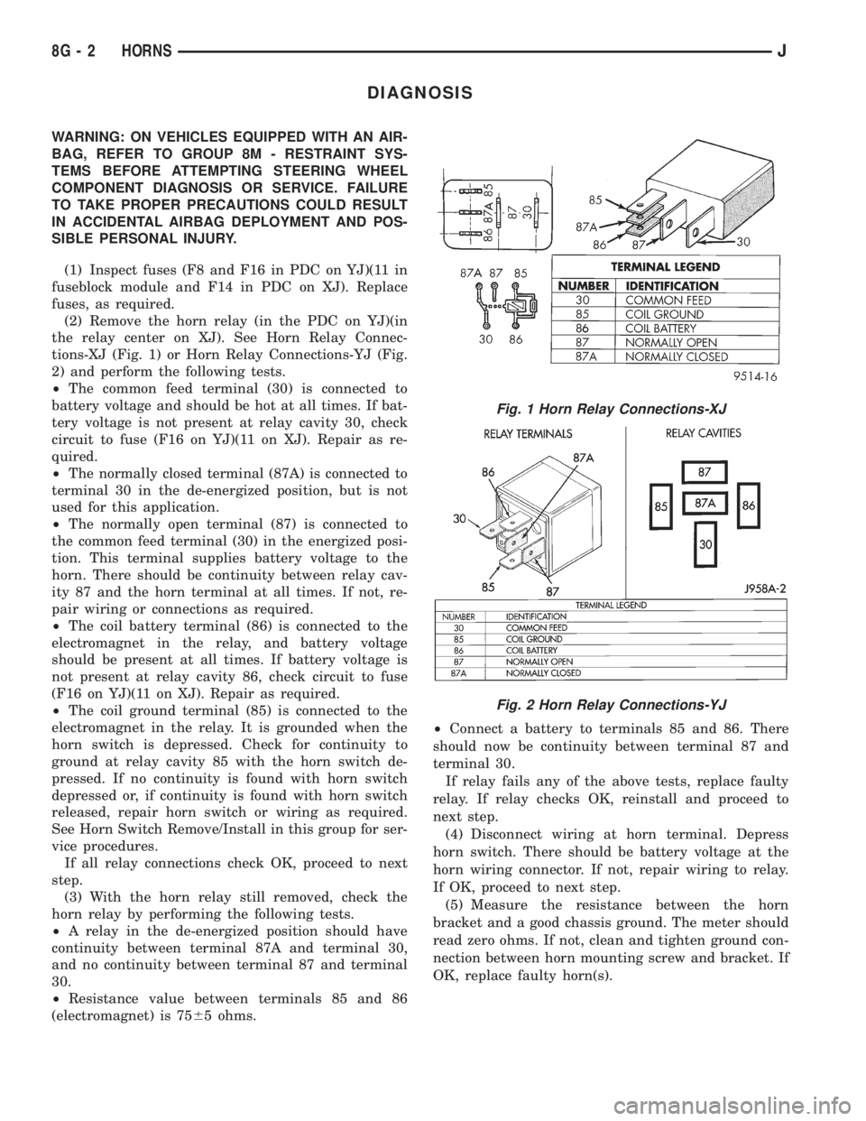
(2) Remove the horn relay (in the PDC on YJ)(in
the relay center on XJ). See Horn Relay Connec-
tions-XJ (Fig. 1) or Horn Relay Connections-YJ (Fig.
2) and perform the following tests.
²The common feed terminal (30) is connected to
battery voltage and should be hot at all times. If bat-
tery voltage is not present at relay cavity 30, check
circuit to fuse (F16 on YJ)(11 on XJ). Repair as re-
quired.
²The normally closed terminal (87A) is connected to
terminal 30 in the de-energized position, but is not
used for this application.
²The normally open terminal (87) is connected to
the common feed terminal (30) in the energized posi-
tion. This terminal supplies battery voltage to the
horn. There should be continuity between relay cav-
ity 87 and the horn terminal at all times. If not, re-
pair wiring or connections as required.
²The coil battery terminal (86) is connected to the
electromagnet in the relay, and battery voltage
should be present at all times. If battery voltage is
not present at relay cavity 86, check circuit to fuse
(F16 on YJ)(11 on XJ). Repair as required.
²The coil ground terminal (85) is connected to the
electromagnet in the relay. It is grounded when the
horn switch is depressed. Check for continuity to
ground at relay cavity 85 with the horn switch de-
pressed. If no continuity is found with horn switch
depressed or, if continuity is found with horn switch
released, repair horn switch or wiring as required.
See Horn Switch Remove/Install in this group for ser-
vice procedures.
If all relay connections check OK, proceed to next
step.
(3) With the horn relay still removed, check the
horn relay by performing the following tests.
²A relay in the de-energized position should have
continuity between terminal 87A and terminal 30,
and no continuity between terminal 87 and terminal
30.
²Resistance value between terminals 85 and 86
(electromagnet) is 7565 ohms.²Connect a battery to terminals 85 and 86. There
should now be continuity between terminal 87 and
terminal 30.
If relay fails any of the above tests, replace faulty
relay. If relay checks OK, reinstall and proceed to
next step.
(4) Disconnect wiring at horn terminal. Depress
horn switch. There should be battery voltage at the
horn wiring connector. If not, repair wiring to relay.
If OK, proceed to next step.
(5) Measure the resistance between the horn
bracket and a good chassis ground. The meter should
read zero ohms. If not, clean and tighten ground con-
nection between horn mounting screw and bracket. If
OK, replace faulty horn(s).
Fig. 1 Horn Relay Connections-XJ
Fig. 2 Horn Relay Connections-YJ
8G - 2 HORNSJ
Page 428 of 2158
allowing current flow to the lamps. As the bimetal
strip cools, the contact points are pushed open and
the cycle repeats.
COMBINATION FLASHER (XJ ONLY)
The combination flasher functions as both the turn
signal and hazard warning flasher on XJ models. The
combination flasher is a smart relay that is located in
the relay center under the lower instrument panel
and inboard of the steering column. The combination
flasher can not be repaired. If faulty, it must be
replaced.
The combination flasher is designed to handle the
current flow requirements of the factory installed
lighting. If supplemental lighting is added to the turn
signal circuits such as when towing a trailer with
lights, the combination flasher will automatically
compensate. This allows the flash rate to remain the
same, regardless of electrical load increases. However,
if a bulb fails in the turn signal or hazard warning
circuits, the flash rate of the remaining bulbs in that
circuit will increase to 120 flashes per minute or
higher.
TURN SIGNAL/HAZARD WARNING SWITCH
(YJ ONLY)
The turn signal and hazard warning switches are
combined into a single unit mounted within the upper
steering column bowl and beneath the steering wheel.
The turn signal lever on the left side of the steering
column is moved up or down to select the right or left
turn signal switch position. The turn signals will only
operate with the ignition switch in the ACCESSORY
or ON position.
The hazard warning button on the right side of the
steering column is pushed in to turn the hazard
warning system on, or pulled out to turn the system
off. The hazard warning system will operate regard-
less of ignition switch position. The turn signal/haz-
ard warning switch can not be repaired. If faulty, the
entire unit must be replaced.
MULTI-FUNCTION SWITCH (XJ ONLY)
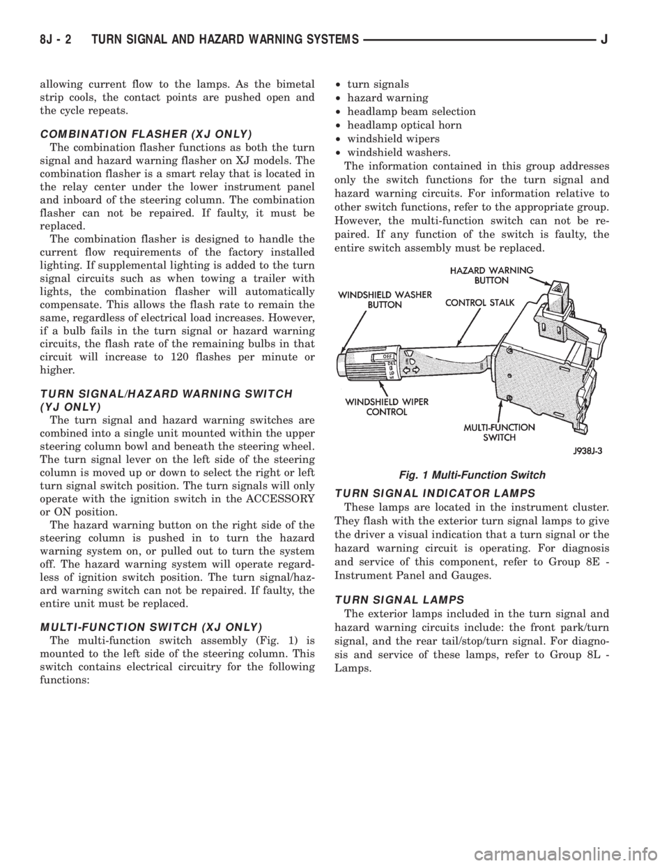
The multi-function switch assembly (Fig. 1) is
mounted to the left side of the steering column. This
switch contains electrical circuitry for the following
functions:²turn signals
²hazard warning
²headlamp beam selection
²headlamp optical horn
²windshield wipers
²windshield washers.
The information contained in this group addresses
only the switch functions for the turn signal and
hazard warning circuits. For information relative to
other switch functions, refer to the appropriate group.
However, the multi-function switch can not be re-
paired. If any function of the switch is faulty, the
entire switch assembly must be replaced.
TURN SIGNAL INDICATOR LAMPS
These lamps are located in the instrument cluster.
They flash with the exterior turn signal lamps to give
the driver a visual indication that a turn signal or the
hazard warning circuit is operating. For diagnosis
and service of this component, refer to Group 8E -
Instrument Panel and Gauges.
TURN SIGNAL LAMPS
The exterior lamps included in the turn signal and
hazard warning circuits include: the front park/turn
signal, and the rear tail/stop/turn signal. For diagno-
sis and service of these lamps, refer to Group 8L -
Lamps.
Fig. 1 Multi-Function Switch
8J - 2 TURN SIGNAL AND HAZARD WARNING SYSTEMSJ
Page 429 of 2158
DIAGNOSIS
When diagnosing the turn signal or hazard warning
circuits, remember that high generator output can
burn out bulbs rapidly and repeatedly. If this is a
problem on the vehicle being diagnosed, refer to
Group 8A - Battery/Starting/Charging Systems Diag-
nostics to test charging system.
WARNING: ON VEHICLES EQUIPPED WITH AN AIR-
BAG, REFER TO GROUP 8M - RESTRAINT SYS-
TEMS BEFORE ATTEMPTING STEERING WHEEL
COMPONENT DIAGNOSIS OR SERVICE. FAILURE
TO TAKE PROPER PRECAUTIONS COULD RESULT
IN ACCIDENTAL AIRBAG DEPLOYMENT AND POS-
SIBLE PERSONAL INJURY.
TURN SIGNAL/HAZARD WARNING SYSTEM - XJ
(1) Turn ignition switch to ON position. Actuate the
turn signal lever or hazard warning button. Observe
the turn indicator lamp(s) in the instrument cluster.
If the flash rate is very high, check for a turn signal
bulb that is not lit. Replace that bulb or repair cir-
cuits to that lamp, as required. Test operation. If turn
indicator does not light, continue to next step.
(2) Remove and inspect fuse 8 (turn signals) in
fuseblock module, or fuse F13 (hazard warning) in the
Power Distribution Center. Replace fuse, if required.
(3) Remove combination flasher from relay center
and replace with a known good unit. Test operation of
turn signal and hazard warning systems. If OK, re-place faulty combination flasher. If not OK, remove
test flasher and go to next step.
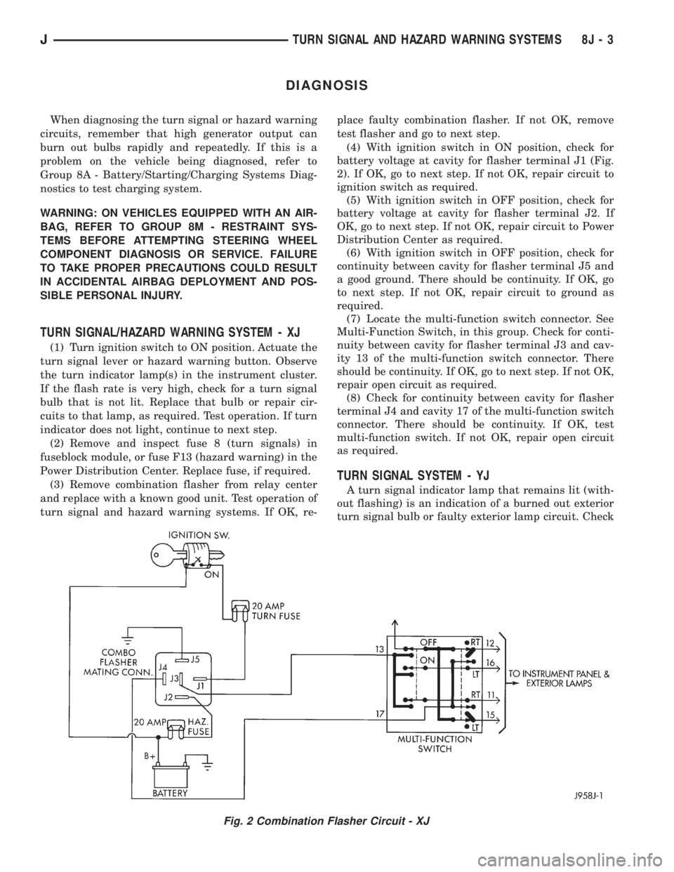
(4) With ignition switch in ON position, check for
battery voltage at cavity for flasher terminal J1 (Fig.
2). If OK, go to next step. If not OK, repair circuit to
ignition switch as required.
(5) With ignition switch in OFF position, check for
battery voltage at cavity for flasher terminal J2. If
OK, go to next step. If not OK, repair circuit to Power
Distribution Center as required.
(6) With ignition switch in OFF position, check for
continuity between cavity for flasher terminal J5 and
a good ground. There should be continuity. If OK, go
to next step. If not OK, repair circuit to ground as
required.
(7) Locate the multi-function switch connector. See
Multi-Function Switch, in this group. Check for conti-
nuity between cavity for flasher terminal J3 and cav-
ity 13 of the multi-function switch connector. There
should be continuity. If OK, go to next step. If not OK,
repair open circuit as required.
(8) Check for continuity between cavity for flasher
terminal J4 and cavity 17 of the multi-function switch
connector. There should be continuity. If OK, test
multi-function switch. If not OK, repair open circuit
as required.
TURN SIGNAL SYSTEM - YJ
A turn signal indicator lamp that remains lit (with-
out flashing) is an indication of a burned out exterior
turn signal bulb or faulty exterior lamp circuit. Check
Fig. 2 Combination Flasher Circuit - XJ
JTURN SIGNAL AND HAZARD WARNING SYSTEMS 8J - 3
Page 461 of 2158
LAMPS
CONTENTS
page page
BULB APPLICATIONÐXJ VEHICLES......... 18
GENERAL INFORMATION.................. 1INTERIOR LAMPS....................... 16
SERVICE PROCEDURES................... 6
GENERAL INFORMATION
Each vehicle is equipped with various lamp assem-
blies. A good ground is necessary for proper lighting
operation. Grounding is provided by the lamp socket
when it comes in contact with the metal body, or
through a separate ground wire.
When changing lamp bulbs check the socket for
corrosion. If corrosion is present, clean it with a wire
brush and coat the inside of the socket lightly with
Mopar Multi-Purpose Grease or equivalent.
DIAGNOSTIC PROCEDURESÐXJ
When a vehicle experiences problems with the
headlamp system, verify the condition of the batteryconnections, charging system, headlamp bulbs, wire
connectors, relay, high beam dimmer switch and
headlamp switch. Refer to Group 8W, Wiring Dia-
grams for component locations and circuit informa-
tion.
Always begin any diagnosis by testing all of the
fuses and circuit breakers in the system. Refer to
Group 8W, Wiring Diagrams.
JLAMPS 8L - 1
Page 467 of 2158
(6) Fuel tank should be FULL. Add 2.94 kg (6.5
lbs.) of weight over the fuel tank for each estimated
gallon of missing fuel.
HEADLAMP/FOG LAMP ADJUSTMENT USING
ALIGNMENT SCREENÐXJ
ALIGNMENT SCREEN PREPARATION
(1) Position vehicle on a level surface perpendicu-
lar to a flat wall 7.62 meters (25 ft) away from front
of headlamp lens (Fig. 1).
(2) If necessary, tape a line on the floor 7.62
meters (25 ft) away from and parallel to the wall.
(3) Measure from the floor up 1.27 meters (5 ft)
and tape a line on the wall at the centerline of the
vehicle. Sight along the centerline of the vehicle
(from rear of vehicle forward) to verify accuracy of
the line placement.
(4) Rock vehicle side-to-side three times to allow
suspension to stabilize.
(5) Jounce front suspension three times by pushing
downward on front bumper and releasing.
(6) Measure the distance from the center of head-
lamp lens to the floor. Transfer measurement to the
alignment screen (with tape). Use this line for up/
down adjustment reference.
(7) Measure distance from the centerline of the ve-
hicle to the center of each headlamp being aligned.
Transfer measurements to screen (with tape) to each
side of vehicle centerline. Use these lines for left/
right adjustment reference.
ADJUSTMENT
(1) Remove screws and both headlamp bezels.
(2) Clean front of the headlamps.
(3) Place headlamps on LOW beam.
(4) Cover front of the headlamp that is not being
adjusted.
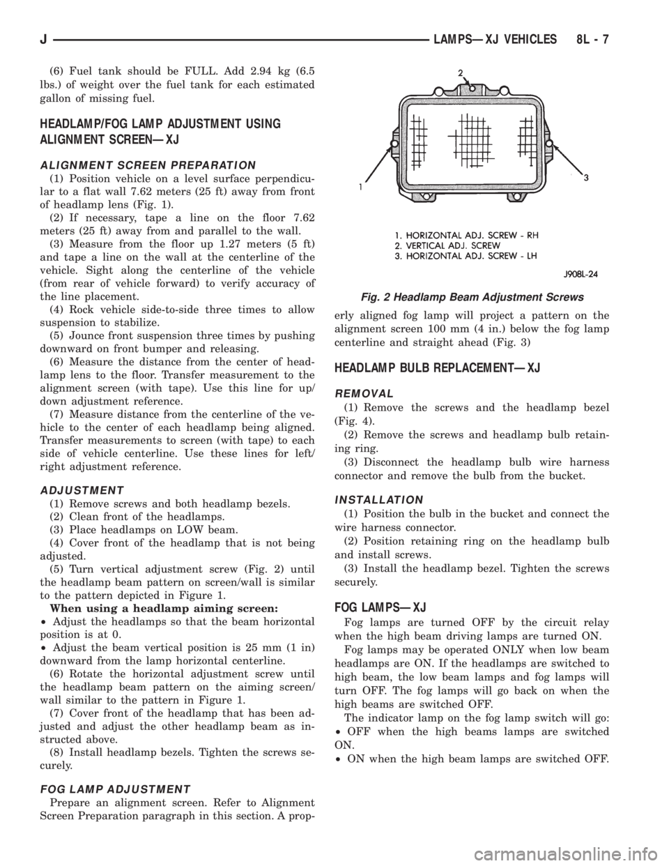
(5) Turn vertical adjustment screw (Fig. 2) until
the headlamp beam pattern on screen/wall is similar
to the pattern depicted in Figure 1.
When using a headlamp aiming screen:
²Adjust the headlamps so that the beam horizontal
position is at 0.
²Adjust the beam vertical position is 25 mm (1 in)
downward from the lamp horizontal centerline.
(6) Rotate the horizontal adjustment screw until
the headlamp beam pattern on the aiming screen/
wall similar to the pattern in Figure 1.
(7) Cover front of the headlamp that has been ad-
justed and adjust the other headlamp beam as in-
structed above.
(8) Install headlamp bezels. Tighten the screws se-
curely.
FOG LAMP ADJUSTMENT
Prepare an alignment screen. Refer to Alignment
Screen Preparation paragraph in this section. A prop-erly aligned fog lamp will project a pattern on the
alignment screen 100 mm (4 in.) below the fog lamp
centerline and straight ahead (Fig. 3)
HEADLAMP BULB REPLACEMENTÐXJ
REMOVAL
(1) Remove the screws and the headlamp bezel
(Fig. 4).
(2) Remove the screws and headlamp bulb retain-
ing ring.
(3) Disconnect the headlamp bulb wire harness
connector and remove the bulb from the bucket.
INSTALLATION
(1) Position the bulb in the bucket and connect the
wire harness connector.
(2) Position retaining ring on the headlamp bulb
and install screws.
(3) Install the headlamp bezel. Tighten the screws
securely.
FOG LAMPSÐXJ
Fog lamps are turned OFF by the circuit relay
when the high beam driving lamps are turned ON.
Fog lamps may be operated ONLY when low beam
headlamps are ON. If the headlamps are switched to
high beam, the low beam lamps and fog lamps will
turn OFF. The fog lamps will go back on when the
high beams are switched OFF.
The indicator lamp on the fog lamp switch will go:
²OFF when the high beams lamps are switched
ON.
²ON when the high beam lamps are switched OFF.
Fig. 2 Headlamp Beam Adjustment Screws
JLAMPSÐXJ VEHICLES 8L - 7
Page 479 of 2158
LAMPS
CONTENTS
page page
BULB APPLICATIONÐYJ VEHICLES......... 32
GENERAL INFORMATION................. 19INTERIOR LAMPS....................... 31
SERVICE PROCEDURES.................. 22
GENERAL INFORMATION
Each vehicle is equipped with various lamp assem-
blies. A good ground is necessary for proper lighting
operation. Grounding is provided by the lamp socket
when it comes in contact with the metal body, or
through a separate ground wire.
When changing lamp bulbs check the socket for
corrosion. If corrosion is present, clean it with a wire
brush and coat the inside of the socket lightly with
Mopar Multi-Purpose Grease or equivalent.
DIAGNOSTIC PROCEDURESÐYJ
When a vehicle experiences problems with the
headlamp system, verify the condition of the batteryconnections, charging system, headlamp bulbs, wire
connectors, relay, high beam dimmer switch and
headlamp switch. Refer to Group 8W, Wiring Dia-
grams for component locations and circuit informa-
tion.
Always begin any diagnosis by testing all of the
fuses and circuit breakers in the system. Refer to
Group 8W, Wiring Diagrams.
JLAMPSÐYJ VEHICLES 8L - 19