tire type JEEP YJ 1995 Service And Repair Manual
[x] Cancel search | Manufacturer: JEEP, Model Year: 1995, Model line: YJ, Model: JEEP YJ 1995Pages: 2158, PDF Size: 81.9 MB
Page 7 of 2158
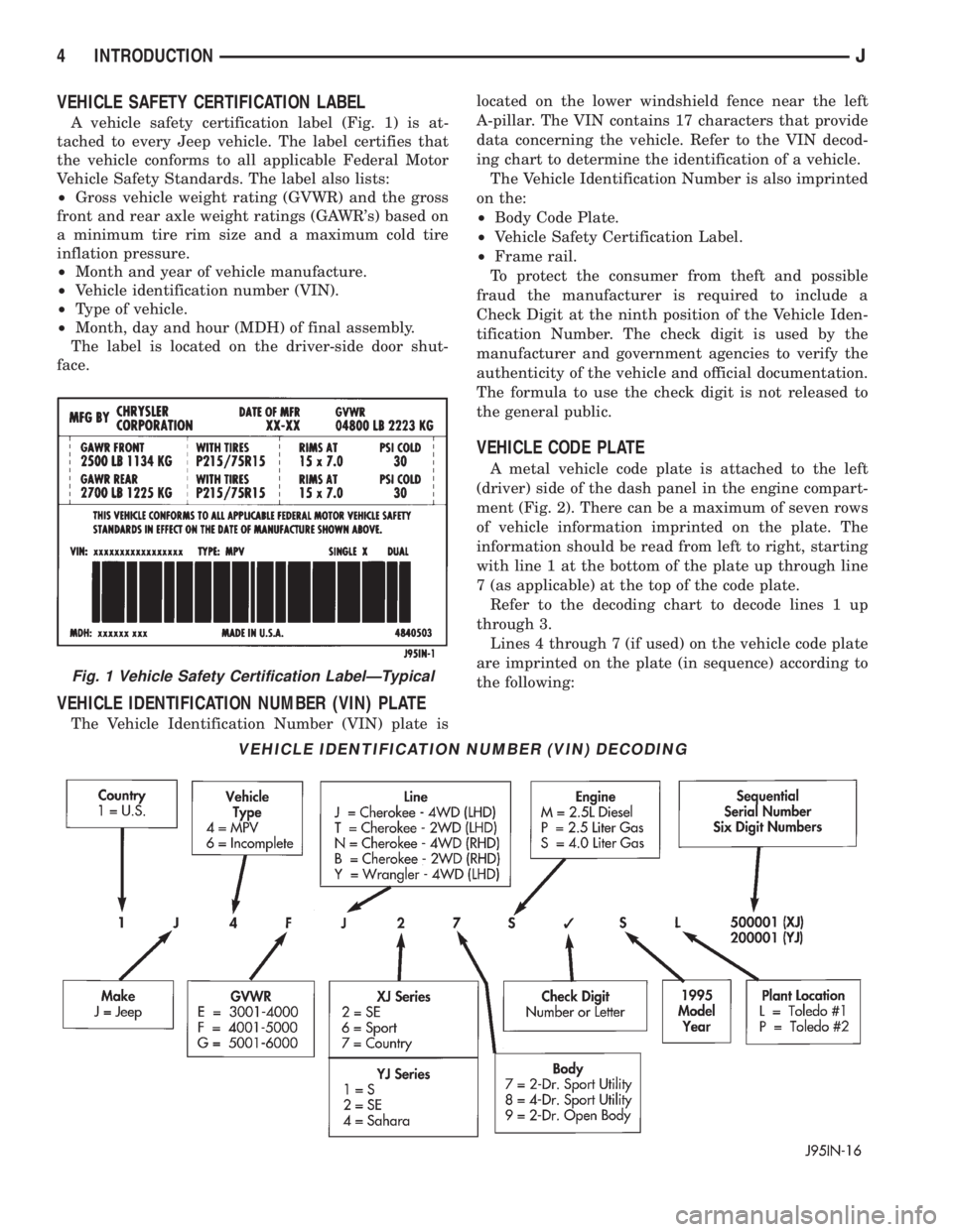
VEHICLE SAFETY CERTIFICATION LABEL
A vehicle safety certification label (Fig. 1) is at-
tached to every Jeep vehicle. The label certifies that
the vehicle conforms to all applicable Federal Motor
Vehicle Safety Standards. The label also lists:
²Gross vehicle weight rating (GVWR) and the gross
front and rear axle weight ratings (GAWR's) based on
a minimum tire rim size and a maximum cold tire
inflation pressure.
²Month and year of vehicle manufacture.
²Vehicle identification number (VIN).
²Type of vehicle.
²Month, day and hour (MDH) of final assembly.
The label is located on the driver-side door shut-
face.
VEHICLE IDENTIFICATION NUMBER (VIN) PLATE
The Vehicle Identification Number (VIN) plate islocated on the lower windshield fence near the left
A-pillar. The VIN contains 17 characters that provide
data concerning the vehicle. Refer to the VIN decod-
ing chart to determine the identification of a vehicle.
The Vehicle Identification Number is also imprinted
on the:
²Body Code Plate.
²Vehicle Safety Certification Label.
²Frame rail.
To protect the consumer from theft and possible
fraud the manufacturer is required to include a
Check Digit at the ninth position of the Vehicle Iden-
tification Number. The check digit is used by the
manufacturer and government agencies to verify the
authenticity of the vehicle and official documentation.
The formula to use the check digit is not released to
the general public.
VEHICLE CODE PLATE
A metal vehicle code plate is attached to the left
(driver) side of the dash panel in the engine compart-
ment (Fig. 2). There can be a maximum of seven rows
of vehicle information imprinted on the plate. The
information should be read from left to right, starting
with line 1 at the bottom of the plate up through line
7 (as applicable) at the top of the code plate.
Refer to the decoding chart to decode lines 1 up
through 3.
Lines 4 through 7 (if used) on the vehicle code plate
are imprinted on the plate (in sequence) according to
the following:
VEHICLE IDENTIFICATION NUMBER (VIN) DECODING
Fig. 1 Vehicle Safety Certification LabelÐTypical
4 INTRODUCTIONJ
Page 23 of 2158
MAINTENANCE SCHEDULES
INTRODUCTION
There are two maintenance schedules that show
proper service intervals for Jeep Cherokee and Jeep
Wrangler vehicles. Use the schedule that best de-
scribes the conditions the vehicle is operated under.
When mileage and time is listed, follow the interval
that occurs first.
ScheduleÐAlists all the scheduled maintenance
to be performed under normal operating conditions.
ScheduleÐBis a schedule for vehicles that are
usually operated under one or more of the following
conditions.
²Frequent short trip driving less than 5 miles (8
km).
²Frequent driving in dusty conditions.
²Trailer towing or heavy load hauling.
²Frequent long periods of engine idling.
²Sustained high speed operation.
²Desert operation.
²Frequent starting and stopping.
²Cold climate operation.
²Off road driving.
²Commercial service.
²Snow plow operation.
²More than half of vehicle operation occurs in
heavy city traffic during hot weather (above 90É F).
AT EACH STOP FOR GASOLINE
²Check engine oil level and add as required.
²Check windshield washer solvent and add as re-
quired.
ONCE A MONTH
²Check tire pressure and look for unusual tire wear
or damage.
²Check fluid levels of coolant reservoir, brake mas-
ter cylinder, power steering and transmission. Add
fluid as required.
²Check all lights and other electrical items for cor-
rect operation.
²Inspect battery and clean and tighten terminals as
required.
²Check rubber seals on each side of the radiator for
proper fit.
AT EACH OIL CHANGE
²Inspect exhaust system.
²Inspect brake hoses.
²Rotate the tires at each oil change interval shown
on ScheduleÐA: (7,500 Miles) or every other interval
shown on ScheduleÐB: (6,000 Miles).
²Check engine coolant level, hoses, and clamps.
²Lubricate 4x4 steering linkage.
²Lubricate propeller shaft universal joints and slip
spline, if equipped.After completion of off-road (4WD) operation, the
underside of the vehicle should be thoroughly in-
spected. Examine threaded fasteners for looseness.
HARSH SURFACE ENVIRONMENTS
After vehicle operation in a harsh surface environ-
ment, the following components should be inspected
and cleaned as soon as possible:
²Brake drums.
²Brake linings.
²Front wheel bearings (2WD vehicles only).
²Axle coupling joints.
This will prevent wear and/or unpredictable brake
action.
EMISSION CONTROL SYSTEM MAINTENANCE
The schedule emission maintenance listed inbold
typeon the following schedules, must be done at the
mileage specified to assure the continued proper
functioning of the emission control system. These,
and all other maintenance services included in this
manual, should be done to provide the best vehicle
performance and reliability. More frequent mainte-
nance may be needed for vehicles in severe operating
conditions such as dusty areas and very short trip
driving.
SCHEDULEÐA
7,500 MILES (12 000 KM) OR AT 6 MONTHS
²Change engine oil.
²Replace engine oil filter.
²Lubricate steering linkage (4x4).
15,000 MILES (24 000 KM) OR AT 12 MONTHS
²Change engine oil.
²Replace engine oil filter.
²Lubricate steering linkage.
22,500 MILES (36 000 KM) OR AT 18 MONTHS
²Change engine oil.
²Replace engine oil filter.
²Lubricate steering linkage (4x4).
²Inspect brake linings.
30,000 MILES (48 000 KM) OR AT 24 MONTHS
²Replace air cleaner element.
²Replace spark plugs.
²Adjust belt tension on non-automatic tensioning
drive belts.
²Change engine oil.
²Replace engine oil filter.
²Lubricate steering linkage.
²Drain and refill automatic transmission.
²Drain and refill transfer case.
0 - 4 LUBRICATION AND MAINTENANCEJ
Page 32 of 2158
4WD YJ VEHICLES
(1) Raise the rear of the vehicle off the ground and
install tow dollies under rear wheels.
CAUTION: Use tow chains with T-hooks for con-
necting to the disabled vehicle's frame rails. Never
use J-hooks.
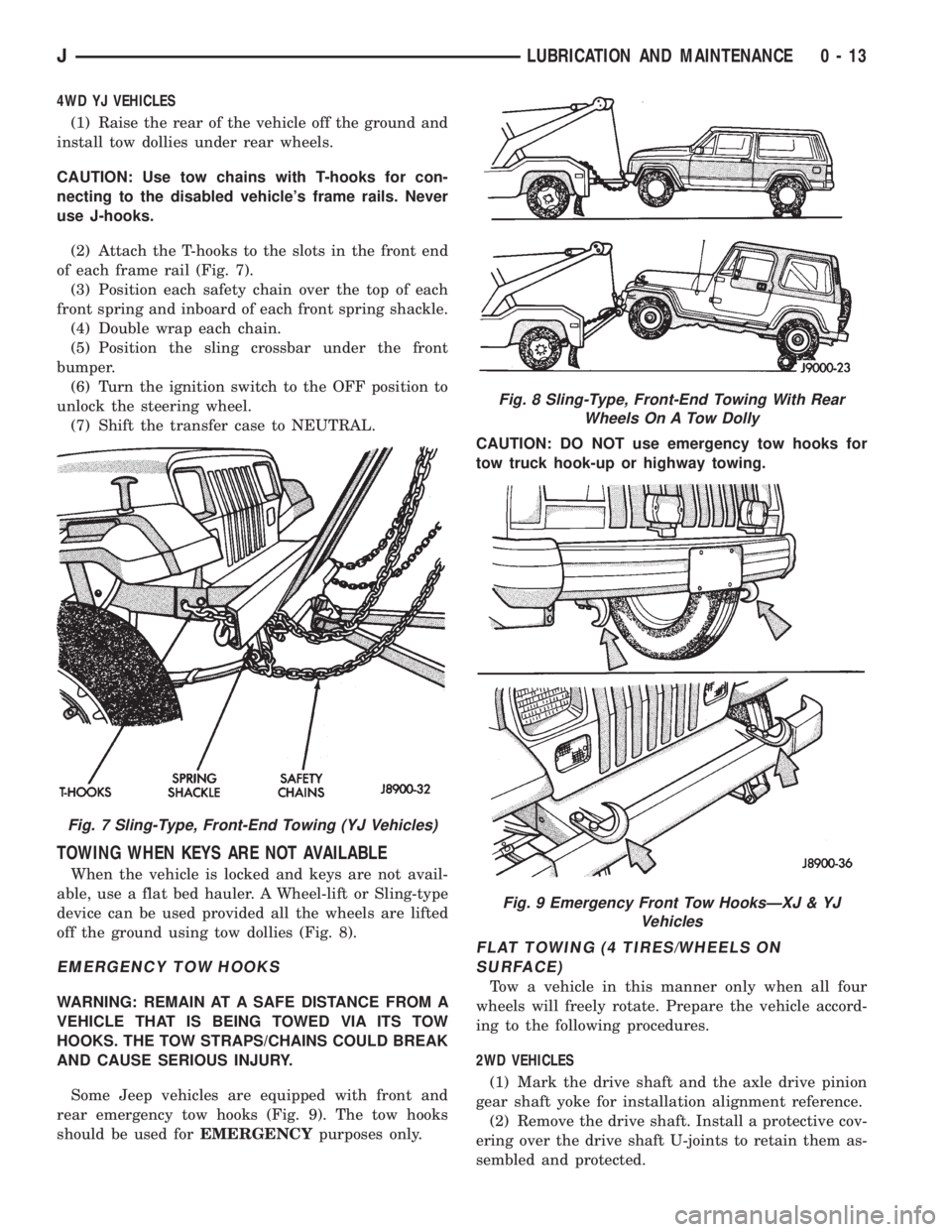
(2) Attach the T-hooks to the slots in the front end
of each frame rail (Fig. 7).
(3) Position each safety chain over the top of each
front spring and inboard of each front spring shackle.
(4) Double wrap each chain.
(5) Position the sling crossbar under the front
bumper.
(6) Turn the ignition switch to the OFF position to
unlock the steering wheel.
(7) Shift the transfer case to NEUTRAL.
TOWING WHEN KEYS ARE NOT AVAILABLE
When the vehicle is locked and keys are not avail-
able, use a flat bed hauler. A Wheel-lift or Sling-type
device can be used provided all the wheels are lifted
off the ground using tow dollies (Fig. 8).
EMERGENCY TOW HOOKS
WARNING: REMAIN AT A SAFE DISTANCE FROM A
VEHICLE THAT IS BEING TOWED VIA ITS TOW
HOOKS. THE TOW STRAPS/CHAINS COULD BREAK
AND CAUSE SERIOUS INJURY.
Some Jeep vehicles are equipped with front and
rear emergency tow hooks (Fig. 9). The tow hooks
should be used forEMERGENCYpurposes only.CAUTION: DO NOT use emergency tow hooks for
tow truck hook-up or highway towing.
FLAT TOWING (4 TIRES/WHEELS ON
SURFACE)
Tow a vehicle in this manner only when all four
wheels will freely rotate. Prepare the vehicle accord-
ing to the following procedures.
2WD VEHICLES
(1) Mark the drive shaft and the axle drive pinion
gear shaft yoke for installation alignment reference.
(2) Remove the drive shaft. Install a protective cov-
ering over the drive shaft U-joints to retain them as-
sembled and protected.
Fig. 7 Sling-Type, Front-End Towing (YJ Vehicles)
Fig. 8 Sling-Type, Front-End Towing With Rear
Wheels On A Tow Dolly
Fig. 9 Emergency Front Tow HooksÐXJ & YJ
Vehicles
JLUBRICATION AND MAINTENANCE 0 - 13
Page 134 of 2158
BEARING AND SEAL INSTALLATION
Do not install the original axle shaft seal. Al-
ways install a new seal.
(1) Wipe the bore in the axle shaft tube clean.
(2) If the original bearing is not reusable, install a
new bearing. Place the axle shaft bearing on the pilot
of Bearing Installer C-4198 and Handle C-4171.
CAUTION: DO NOT use the new axle shaft seal to
position or seat the bearing in the axle shaft bore.
(3) Insert the bearing into the tube. Ensure that
the bearing is not cocked and is seated firmly against
the tube shoulder.
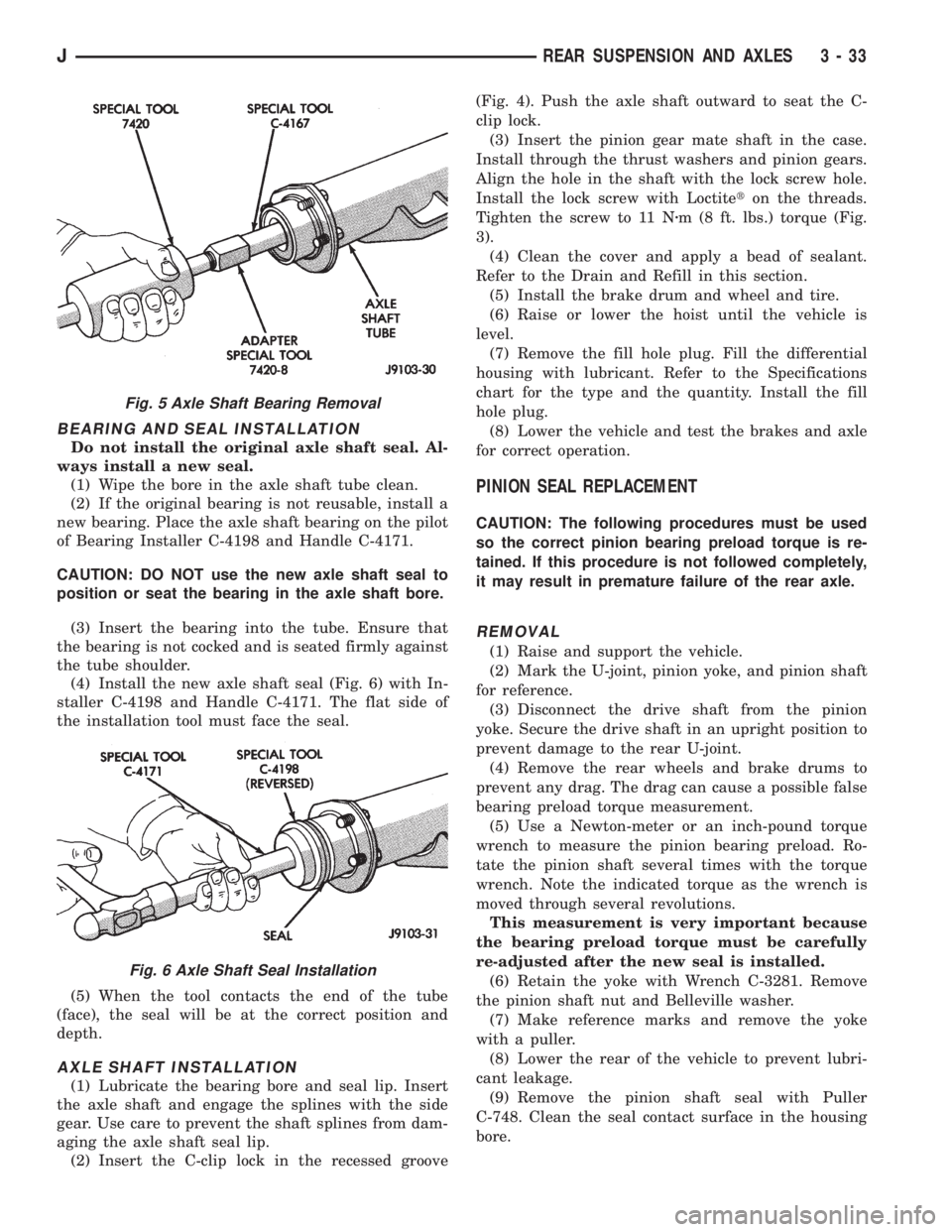
(4) Install the new axle shaft seal (Fig. 6) with In-
staller C-4198 and Handle C-4171. The flat side of
the installation tool must face the seal.
(5) When the tool contacts the end of the tube
(face), the seal will be at the correct position and
depth.
AXLE SHAFT INSTALLATION
(1) Lubricate the bearing bore and seal lip. Insert
the axle shaft and engage the splines with the side
gear. Use care to prevent the shaft splines from dam-
aging the axle shaft seal lip.
(2) Insert the C-clip lock in the recessed groove(Fig. 4). Push the axle shaft outward to seat the C-
clip lock.
(3) Insert the pinion gear mate shaft in the case.
Install through the thrust washers and pinion gears.
Align the hole in the shaft with the lock screw hole.
Install the lock screw with Loctiteton the threads.
Tighten the screw to 11 Nzm (8 ft. lbs.) torque (Fig.
3).
(4) Clean the cover and apply a bead of sealant.
Refer to the Drain and Refill in this section.
(5) Install the brake drum and wheel and tire.
(6) Raise or lower the hoist until the vehicle is
level.
(7) Remove the fill hole plug. Fill the differential
housing with lubricant. Refer to the Specifications
chart for the type and the quantity. Install the fill
hole plug.
(8) Lower the vehicle and test the brakes and axle
for correct operation.
PINION SEAL REPLACEMENT
CAUTION: The following procedures must be used
so the correct pinion bearing preload torque is re-
tained. If this procedure is not followed completely,
it may result in premature failure of the rear axle.
REMOVAL
(1) Raise and support the vehicle.
(2) Mark the U-joint, pinion yoke, and pinion shaft
for reference.
(3) Disconnect the drive shaft from the pinion
yoke. Secure the drive shaft in an upright position to
prevent damage to the rear U-joint.
(4) Remove the rear wheels and brake drums to
prevent any drag. The drag can cause a possible false
bearing preload torque measurement.
(5) Use a Newton-meter or an inch-pound torque
wrench to measure the pinion bearing preload. Ro-
tate the pinion shaft several times with the torque
wrench. Note the indicated torque as the wrench is
moved through several revolutions.
This measurement is very important because
the bearing preload torque must be carefully
re-adjusted after the new seal is installed.
(6) Retain the yoke with Wrench C-3281. Remove
the pinion shaft nut and Belleville washer.
(7) Make reference marks and remove the yoke
with a puller.
(8) Lower the rear of the vehicle to prevent lubri-
cant leakage.
(9) Remove the pinion shaft seal with Puller
C-748. Clean the seal contact surface in the housing
bore.
Fig. 5 Axle Shaft Bearing Removal
Fig. 6 Axle Shaft Seal Installation
JREAR SUSPENSION AND AXLES 3 - 33
Page 155 of 2158
ABS BRAKE DIAGNOSIS
INDEX
page page
ABS Diagnostic Connector................... 3
ABS Warning Light Display................... 3
Antilock ECU and Hcu Diagnosis............... 3
DRB Scan Tool............................ 3General Information........................ 3
Normal Operating Conditions.................. 3
Wheel/Tire Size and Input Signals.............. 3
GENERAL INFORMATION
The DRB scan tool is required for ABS diagnosis.
The scan tool is used to identify ABS circuit faults.
Once a faulty circuit has been identified, refer to
the appropriate chassis/body diagnostic manual for
individual component testing.
ABS WARNING LIGHT DISPLAY
The amber antilock light illuminates at startup as
part of the system self check feature. The light illu-
minates for 2-3 seconds then goes off as part of the
normal check routine.
An ABS circuit fault is indicated when the amber
light remains on after startup, or illuminates during
vehicle operation.
Verify that a fault is actually related to the ABS
system before making repairs. For example, if the
red warning illuminates but the ABS light does not,
the problem is related to a service brake component
and not the ABS system. Or, if neither light illumi-
nates but a brake problem is noted, again, the prob-
lem is with a service brake component and not with
the ABS system.
ABS DIAGNOSTIC CONNECTOR
The ABS diagnostic connector is inside the vehicle.
The connector is the access point for the DRB scan tool.
On XJ models, the connector is located under the
instrument panel to the right of the steering column.
On some models, the connecter may be tucked under
the carpeting on the transmission tunnel. The con-
necter is a black, 6-way type.
On YJ models, the connector is under the instru-
ment panel by the the driver side kick panel. The
connecter is a black, 6 or 8-way type.
The DRB scan tool kit contains adapter cords for
both types of connecter. Use the appropriate cord for
test hookup.
DRB SCAN TOOL
ABS diagnosis is performed with the DRB scan tool.
Refer to the DRB scan tool manual for test hookup and
procedures. Diagnosis information is provided in the ap-
propriate chassis/body diagnostic manual.
WHEEL/TIRE SIZE AND INPUT SIGNALS
Antilock system operation is dependant on accurate
signals from the wheel speed sensors. Ideally, the ve-
hicle wheels and tires should all be the same size
and type. However, the Jeep ABS system is designed
to operate with a compact spare tire installed.
NORMAL OPERATING CONDITIONS
Sound Levels
The hydraulic control unit pump and solenoid valves
may produce some sound as they cycle on and off. This
is a normal condition and should not be mistaken for
faulty operation. Under most conditions, pump and so-
lenoid valve operating sounds will not be audible.
Vehicle Response In Antilock Mode
During antilock braking, the hydraulic control unit
solenoid valves cycle rapidly in response to antilock
electronic control unit signals.
The driver will experience a pulsing sensation
within the vehicle as the solenoids decrease, hold, or
increase pressure as needed. Brake pedal pulsing will
also be noted and is anormal condition.
Steering Response
A modest amount of steering input is required dur-
ing extremely high deceleration braking, or when
braking on differing traction surfaces. An example of
differing traction surfaces would be when the left
side wheels are on ice and the right side wheels are
on dry pavement.
Owner Induced Faults
Driving away with the parking brakes still applied
will cause warning light illumination. Pumping the
brake pedal will also generate a system fault and in-
terfere with ABS system operation.
ANTILOCK ECU AND HCU DIAGNOSIS
An ECU or HCU fault can only be determined
through testing with the DRB scan tool. Do not re-
place either component unless a fault is actually in-
dicated.
JABS BRAKE DIAGNOSIS 5 - 3
Page 158 of 2158
pedal. The proper course of action is to bleed the sys-
tem, or replace thin drums and suspect quality brake
lines and hoses.
HARD PEDAL OR HIGH PEDAL EFFORT
A hard pedal or high pedal effort may be due to lin-
ing that is water soaked, contaminated, glazed, or
badly worn. The power booster or check valve could
also be faulty. Test the booster and valve as described
in this section.
BRAKE DRAG
Brake drag occurs when the lining is in constant
contact with the rotor or drum. Drag can occur at one
wheel, all wheels, fronts only, or rears only. It is a
product of incomplete brakeshoe release. Drag can be
minor or severe enough to overheat the linings, ro-
tors and drums. A drag condition also worsens as
temperature of the brake parts increases.
Brake drag also has a direct effect on fuel economy.
If undetected, minor brake drag can be misdiagnosed
as an engine or transmission/torque converter prob-
lem.
Minor drag will usually cause slight surface char-
ring of the lining. It can also generate hard spots in
rotors and drums from the overheat/cool down pro-
cess. In most cases, the rotors, drums, wheels and
tires are quite warm to the touch after the vehicle is
stopped.
Severe drag can char the brake lining all the way
through. It can also distort and score rotors and
drums to the point of replacement. The wheels, tires
and brake components will be extremely hot. In se-
vere cases, the lining may generate smoke as it chars
from overheating.
An additional cause of drag involves the use of in-
correct length caliper mounting bolts. Bolts that are
too long can cause a partial apply condition. The cor-
rect caliper bolts have a shank length of 67 mm
(2.637 in.), plus or minus 0.6 mm (0.0236 in.). Refer
to the Disc Brake service section for more detail on
caliper bolt dimensions and identification.
Some common causes of brake drag are:
²loose or damaged wheel bearing
²seized or sticking caliper or wheel cylinder piston
²caliper binding on bolts or slide surfaces
²wrong length caliper mounting bolts (too long)
²loose caliper mounting bracket
²distorted rotor, brake drum, or shoes
²brakeshoes binding on worn/damaged support
plates
²severely rusted/corroded components
²misassembled components.
If brake drag occurs at all wheels, the problem may
be related to a blocked master cylinder compensatorport or faulty power booster (binds-does not release).
The condition will worsen as brake temperature in-
creases.
The brakelight switch can also be a cause of drag.
An improperly mounted or adjusted brakelight
switch can prevent full brake pedal return. The re-
sult will be the same as if the master cylinder com-
pensator ports are blocked. The brakes would be
partially applied causing drag.
BRAKE FADE
Brake fade is a product of overheating caused by
brake drag. However, overheating and subsequent
fade can also be caused by riding the brake pedal,
making repeated high deceleration stops in a short
time span, or constant braking on steep roads. Refer
to the Brake Drag information in this section for
causes.
PEDAL PULSATION (NON-ABS BRAKES ONLY)
Pedal pulsation is caused by parts that are loose,
or beyond tolerance limits. This type of pulsation is
constant and will occur every time the brakes are ap-
plied.
Disc brake rotors with excessive lateral runout or
thickness variation, or out of round brake drums are
the primary causes of pulsation.
On vehicles with ABS brakes, remember that pedal
pulsation is normal during antilock mode brake
stops. If pulsation occurs during light to moderate
brake stops, a standard brake part is either loose, or
worn beyond tolerance.
BRAKE PULL
A front pull condition could be the result of:
²contaminated lining in one caliper
²seized caliper piston
²binding caliper
²wrong caliper mounting bolts (too long)
²loose caliper
²loose or corroded mounting bolts
²improper brakeshoes
²damaged rotor
²incorrect wheel bearing adjustment (at one wheel)
A worn, damaged wheel bearing or suspension com-
ponent are further causes of pull. A damaged front
tire (bruised, ply separation) can also cause pull.
Wrong caliper bolts (too long) will cause a partial ap-
ply condition and pull if only one caliper is involved.
A common and frequently misdiagnosed pull condi-
tion is where direction of pull changes after a few
stops. The cause is a combination of brake drag fol-
lowed by fade at the dragging brake unit.
As the dragging brake overheats, efficiency is so re-
duced that fade occurs. If the opposite brake unit is
still functioning normally, its braking effect is magni-
5 - 6 SERVICE BRAKE DIAGNOSISJ
Page 159 of 2158
fied. This causes pull to switch direction in favor of
the brake unit that is functioning normally.
When diagnosing a change in pull condition, re-
member that pull will return to the original direction
if the dragging brake unit is allowed to cool down
(and is not seriously damaged).
REAR BRAKE GRAB
Rear grab (or pull) is usually caused by contami-
nated lining, bent or binding shoes and support
plates, or improperly assembled components. This is
particularly true when only one rear wheel is in-
volved. However, when both rear wheels are affected,
the master cylinder could be at fault.
BRAKES DO NOT HOLD AFTER DRIVING THROUGH
DEEP WATER PUDDLES
This condition is caused by water soaked lining. If
the lining is only wet, it can be dried by driving with
the brakes lightly applied for a mile or two. However,
if the lining is both wet and dirty, disassembly and
cleaning will be necessary.
CONTAMINATED BRAKELINING
Brakelining contaminated by water is salvageable.
The lining can either be air dried or dried using heat.
In cases where brakelining is contaminated by oil,
grease, or brake fluid, the lining should be replaced.
Replacement is especially necessary when fluids/lu-
bricants have actually soaked into the lining mate-
rial. However, grease or dirt that gets onto the lining
surface (from handling) during brake repairs, can be
cleaned off. Spray the lining surface clean with Mo-
par brake cleaner.
BRAKE FLUID CONTAMINATION
There are two basic causes of brake fluid contami-
nation. The first involves allowing dirt, debris, or
other materials to enter the cylinder reservoirs when
the cover is off. The second involves adding non-rec-
ommended fluids to the cylinder reservoirs.
Brake fluid contaminated with only dirt, or debris
usually retains a normal appearance. In some cases,
the foreign material will remain suspended in the
fluid and be visible. The fluid and foreign material
can be removed from the reservoir with a suction gun
but only if the brakes have not been applied. If the
brakes are applied after contamination, system flush-
ing will be required. The master cylinder may also
have to be disassembled, cleaned and the piston seals
replaced. Foreign material lodged in the reservoir
compensator/return ports can cause brake drag by re-
stricting fluid return after brake application.
Brake fluid contaminated by a non-recommended
fluid may appear discolored, milky, oily looking, or
foamy. However, remember that brake fluid will
darken in time and occasionally be cloudy in appear-ance. These are normal conditions and should not be
mistaken for contamination.
If some type of oil has been added to the system,
the fluid will separate into distinct layers. To verify
this, drain off a sample with a clean suction gun.
Then pour the sample into a glass container and ob-
serve fluid action. If the fluid separates into distinct
layers, it is definitely contaminated.
The only real correction for contamination by non-
recommended fluid is to flush the entire hydraulic
system and replace all the seals.
BRAKE NOISE
Squeak/Squeal
Factory installed brakelining is made from as-
bestos free materials. These materials have dif-
ferent operating characteristics than previous
lining material. Under certain conditions, as-
bestos free lining may generate some squeak,
groan or chirp noise. This noise is considered
normal and does not indicate a problem. The
only time inspection is necessary, is when noise
becomes constant or when grinding, scraping
noises occur.
Constant brake squeak or squeal may be due to lin-
ings that are wet or contaminated with brake fluid,
grease, or oil. Glazed linings, rotors/drums with hard
spots, and dirt/foreign material embedded in the
brake lining also cause squeak. Loud squeak, squeal,
scraping, or grinding sounds are a sign of severely
worn brake lining. If the lining has worn completely
through in spots, metal-to-metal contact occurs.
Thump/Clunk
Thumping or clunk noises during braking are fre-
quentlynotcaused by brake components. In many
cases, such noises are caused by loose or damaged
steering, suspension, or engine components. However,
calipers that bind on the slide surfaces can generate
a thump or clunk noise. In addition, worn out, im-
properly adjusted, or improperly assembled rear
brakeshoes can also produce a thump noise.
Chatter/Shudder
Brake chatter, or shudder is usually caused by
loose or worn components, or glazed/burnt lining. Ro-
tors with hard spots can also contribute to chatter.
Additional causes of chatter are out of tolerance ro-
tors, brake lining not securely attached to the shoes,
loose wheel bearings and contaminated brake lining.
WHEEL AND TIRE PROBLEMS
Some conditions attributed to brake components
may actually be caused by a wheel or tire problem.
A damaged wheel can cause shudder, vibration and
pull. A worn or damaged tire can also cause pull.
Severely worn tires with very little tread left can
JSERVICE BRAKE DIAGNOSIS 5 - 7
Page 302 of 2158
CHARGING SYSTEM
GENERAL INFORMATION
The charging system consists of:
²generator
²voltage regulator circuitry (within PCM)
²ignition switch
²battery
²generator warning lamp or voltmeter (depending
on vehicle equipment)
²wiring harness and connections.
Following is a general description of the major
charging system components. Refer to Group 8W -
Wiring Diagrams for complete circuit descriptions
and diagrams.
The charging system is turned on and off with the
ignition switch. When the ignition switch is turned to
the ON position, battery voltage is applied to the
generator rotor through one of the two field termi-
nals to produce a magnetic field. The generator is
driven by the engine through a serpentine belt and
pulley arrangement.
As the energized rotor begins to rotate within the
generator, the spinning magnetic field induces a cur-
rent into the windings of the stator coil. Once the
generator begins producing sufficient current, it also
provides the current needed to energize the rotor.
The wye (Y) type stator winding connections de-
liver the induced AC current to 3 positive and 3 neg-
ative diodes for rectification. From the diodes,
rectified DC current is delivered to the vehicle elec-
trical system through the generator battery and
ground terminals.
The amount of DC current produced by the gener-
ator is controlled by the generator voltage regulator
(field control) circuitry, contained within the Power-
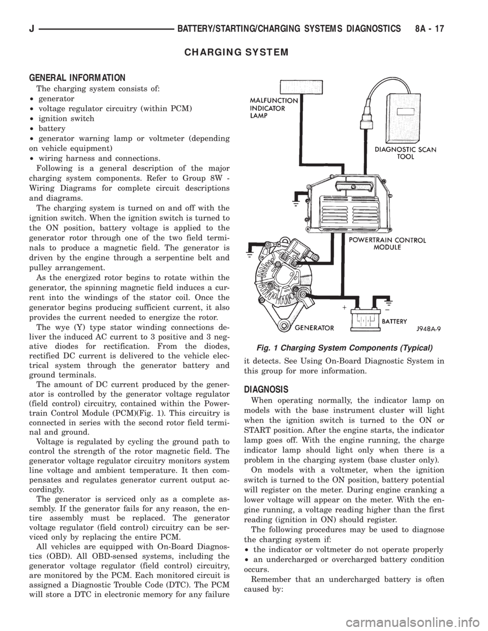
train Control Module (PCM)(Fig. 1). This circuitry is
connected in series with the second rotor field termi-
nal and ground.
Voltage is regulated by cycling the ground path to
control the strength of the rotor magnetic field. The
generator voltage regulator circuitry monitors system
line voltage and ambient temperature. It then com-
pensates and regulates generator current output ac-
cordingly.
The generator is serviced only as a complete as-
sembly. If the generator fails for any reason, the en-
tire assembly must be replaced. The generator
voltage regulator (field control) circuitry can be ser-
viced only by replacing the entire PCM.
All vehicles are equipped with On-Board Diagnos-
tics (OBD). All OBD-sensed systems, including the
generator voltage regulator (field control) circuitry,
are monitored by the PCM. Each monitored circuit is
assigned a Diagnostic Trouble Code (DTC). The PCM
will store a DTC in electronic memory for any failureit detects. See Using On-Board Diagnostic System in
this group for more information.
DIAGNOSIS
When operating normally, the indicator lamp on
models with the base instrument cluster will light
when the ignition switch is turned to the ON or
START position. After the engine starts, the indicator
lamp goes off. With the engine running, the charge
indicator lamp should light only when there is a
problem in the charging system (base cluster only).
On models with a voltmeter, when the ignition
switch is turned to the ON position, battery potential
will register on the meter. During engine cranking a
lower voltage will appear on the meter. With the en-
gine running, a voltage reading higher than the first
reading (ignition in ON) should register.
The following procedures may be used to diagnose
the charging system if:
²the indicator or voltmeter do not operate properly
²an undercharged or overcharged battery condition
occurs.
Remember that an undercharged battery is often
caused by:
Fig. 1 Charging System Components (Typical)
JBATTERY/STARTING/CHARGING SYSTEMS DIAGNOSTICS 8A - 17
Page 312 of 2158
CAUTION: Be certain that battery cables are con-
nected to the correct battery terminals. Reverse po-
larity can damage electrical components.
(12) Place oiled felt washer on battery positive ter-
minal post.
(13) Install and tighten battery positive cable ter-
minal clamp. Then install and tighten negative cableterminal clamp. Both cable clamp bolts require
torque of 8.5 Nzm (75 in. lbs.).
(14) Apply a thin coating of petroleum jelly or
chassis grease to cable terminals and battery posts.
STARTER AND STARTER RELAY
GENERAL INFORMATION
This section covers starter and starter relay service
procedures only. For diagnostic procedures, refer to
Group 8A - Battery/Starting/Charging Systems Diag-
nostics. Service procedures for other starting system
components can be found as follows:
²battery - see Battery, in this group
²ignition switch - refer to Group 8D - Ignition Sys-
tems
²park/neutral position switch (automatic transmis-
sion) - refer to Group 21 - Transmission and Transfer
Case
²wiring harness and connectors - refer to Group 8W
- Wiring Diagrams.
STARTER
The starter motor incorporates several features to
create a reliable, efficient, compact and lightweight
unit. A planetary gear system (intermediate trans-
mission) is used between the electric motor and pin-
ion gear. This feature makes it possible to reduce the
dimensions of the starter. At the same time, it allows
higher armature rotational speed and delivers in-
creased torque through the pinion gear to the fly-
wheel or drive plate ring gear.
The use of a permanent magnet field also reduces
starter size and weight. This field consists of six
high-strength permanent magnets. The magnets are
aligned according to their polarity and are perma-
nently fixed in the starter field frame.
The starter motors for all engines are activated by
a solenoid mounted to the overrunning clutch hous-
ing. However, the starter motor/solenoid are serviced
only as a complete assembly. If either component
fails, the entire assembly must be replaced.
This unit is highly sensitive to hammering, shocks
and external pressure.
CAUTION: The starter motor MUST NOT BE
CLAMPED in a vise by the starter field frame. Doing
so may damage the magnets. It may be clamped by
the mounting flange ONLY.CAUTION: Do not connect starter motor incorrectly
when tests are being performed. The permanent
magnets may be damaged and rendered unservice-
able.
STARTER RELAY
The starter relay is an International Standards Or-
ganization (ISO) type relay, and is located in the
Power Distribution Center (PDC). Refer to underside
of PDC cover for relay location.
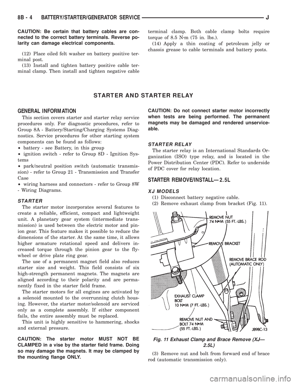
STARTER REMOVE/INSTALLÐ2.5L
XJ MODELS
(1) Disconnect battery negative cable.
(2) Remove exhaust clamp from bracket (Fig. 11).
(3) Remove nut and bolt from forward end of brace
rod (automatic transmission only).
Fig. 11 Exhaust Clamp and Brace Remove (XJÐ
2.5L)
8B - 4 BATTERY/STARTER/GENERATOR SERVICEJ
Page 338 of 2158
temperature ranges. This depends upon the thick-
ness and length of the center electrodes porcelain in-
sulator.)
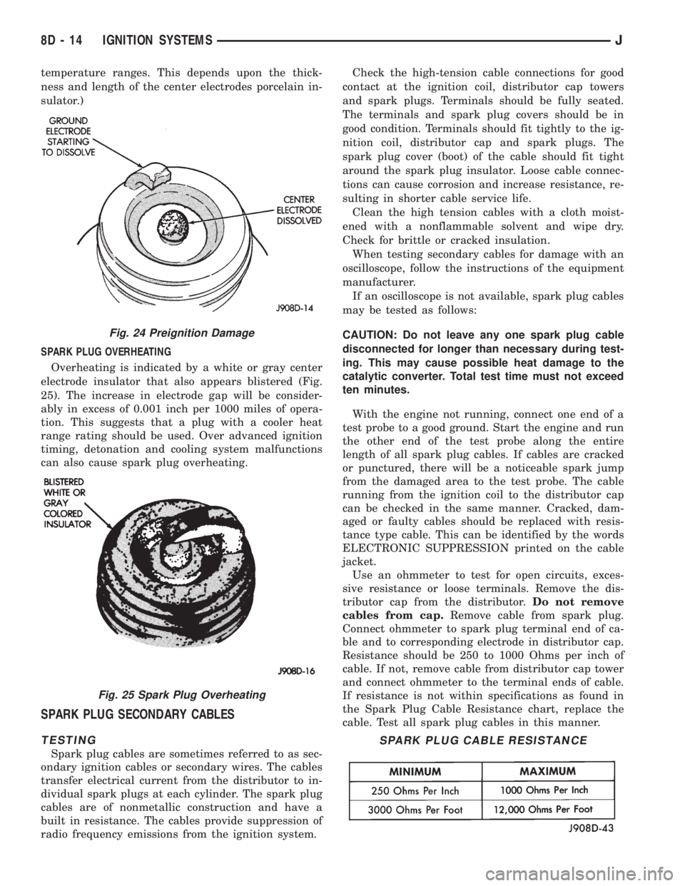
SPARK PLUG OVERHEATING
Overheating is indicated by a white or gray center
electrode insulator that also appears blistered (Fig.
25). The increase in electrode gap will be consider-
ably in excess of 0.001 inch per 1000 miles of opera-
tion. This suggests that a plug with a cooler heat
range rating should be used. Over advanced ignition
timing, detonation and cooling system malfunctions
can also cause spark plug overheating.
SPARK PLUG SECONDARY CABLES
TESTING
Spark plug cables are sometimes referred to as sec-
ondary ignition cables or secondary wires. The cables
transfer electrical current from the distributor to in-
dividual spark plugs at each cylinder. The spark plug
cables are of nonmetallic construction and have a
built in resistance. The cables provide suppression of
radio frequency emissions from the ignition system.Check the high-tension cable connections for good
contact at the ignition coil, distributor cap towers
and spark plugs. Terminals should be fully seated.
The terminals and spark plug covers should be in
good condition. Terminals should fit tightly to the ig-
nition coil, distributor cap and spark plugs. The
spark plug cover (boot) of the cable should fit tight
around the spark plug insulator. Loose cable connec-
tions can cause corrosion and increase resistance, re-
sulting in shorter cable service life.
Clean the high tension cables with a cloth moist-
ened with a nonflammable solvent and wipe dry.
Check for brittle or cracked insulation.
When testing secondary cables for damage with an
oscilloscope, follow the instructions of the equipment
manufacturer.
If an oscilloscope is not available, spark plug cables
may be tested as follows:
CAUTION: Do not leave any one spark plug cable
disconnected for longer than necessary during test-
ing. This may cause possible heat damage to the
catalytic converter. Total test time must not exceed
ten minutes.
With the engine not running, connect one end of a
test probe to a good ground. Start the engine and run
the other end of the test probe along the entire
length of all spark plug cables. If cables are cracked
or punctured, there will be a noticeable spark jump
from the damaged area to the test probe. The cable
running from the ignition coil to the distributor cap
can be checked in the same manner. Cracked, dam-
aged or faulty cables should be replaced with resis-
tance type cable. This can be identified by the words
ELECTRONIC SUPPRESSION printed on the cable
jacket.
Use an ohmmeter to test for open circuits, exces-
sive resistance or loose terminals. Remove the dis-
tributor cap from the distributor.Do not remove
cables from cap.Remove cable from spark plug.
Connect ohmmeter to spark plug terminal end of ca-
ble and to corresponding electrode in distributor cap.
Resistance should be 250 to 1000 Ohms per inch of
cable. If not, remove cable from distributor cap tower
and connect ohmmeter to the terminal ends of cable.
If resistance is not within specifications as found in
the Spark Plug Cable Resistance chart, replace the
cable. Test all spark plug cables in this manner.
Fig. 24 Preignition Damage
Fig. 25 Spark Plug Overheating
SPARK PLUG CABLE RESISTANCE
8D - 14 IGNITION SYSTEMSJ