ABS KIA Amanti 2004 1.G User Guide
[x] Cancel search | Manufacturer: KIA, Model Year: 2004, Model line: Amanti, Model: KIA Amanti 2004 1.GPages: 296, PDF Size: 29.34 MB
Page 204 of 296
Driving tips18
5
1
2
3
4
5
6
7
8
9
Parking on hills Generally, you should not park your
vehicle, with a trailer attached, on a
hill. People can be seriously or fatal-
ly injured, and both your vehicle and
the trailer can be damaged if they
begin a downhill trajectory. However, if you ever have to park
your trailer on a hill, here’s how to do
it:
1. Apply your brakes, but don’t shift
into gear.
2. Have someone place chocks under the trailer wheels.
3. When the wheel chocks are in place, release the brakes until the
chocks absorb the load.
4. Reapply the brakes. Apply your parking brake, and then shift to P
(Park) for an automatic transaxle.
5. Release the brakes.
When you are ready to leave after parking on a hill 1. With the automatic transaxle in P (Park), apply your brakes and hold
the brake pedal down while you:
Start your engine;
Shift into gear; and
Release the parking brake.
2. Slowly remove your foot from the brake pedal.
3. Drive slowly until the trailer is clear of the chocks.
4. Stop and have someone pick up and store the chocks.
WARNING
- Parking brake
It can be dangerous to get out of
your vehicle if the parking brake
is not firmly set.
If you have left the engine run-
ning, the vehicle can move sud-
denly. You or others could be
seriously or fatally injured.
WARNING
- Parking on a hill
Parking your vehicle on a hill
with a trailer attached could
cause serious injury or death,
should a down hill trajectory
happen.
Opirus CAN 5-1.qxd 7/8/03 2:21 PM Page 18
Page 224 of 296
611
In case of an emergency
1
2
3
4
5
6
7
8
9
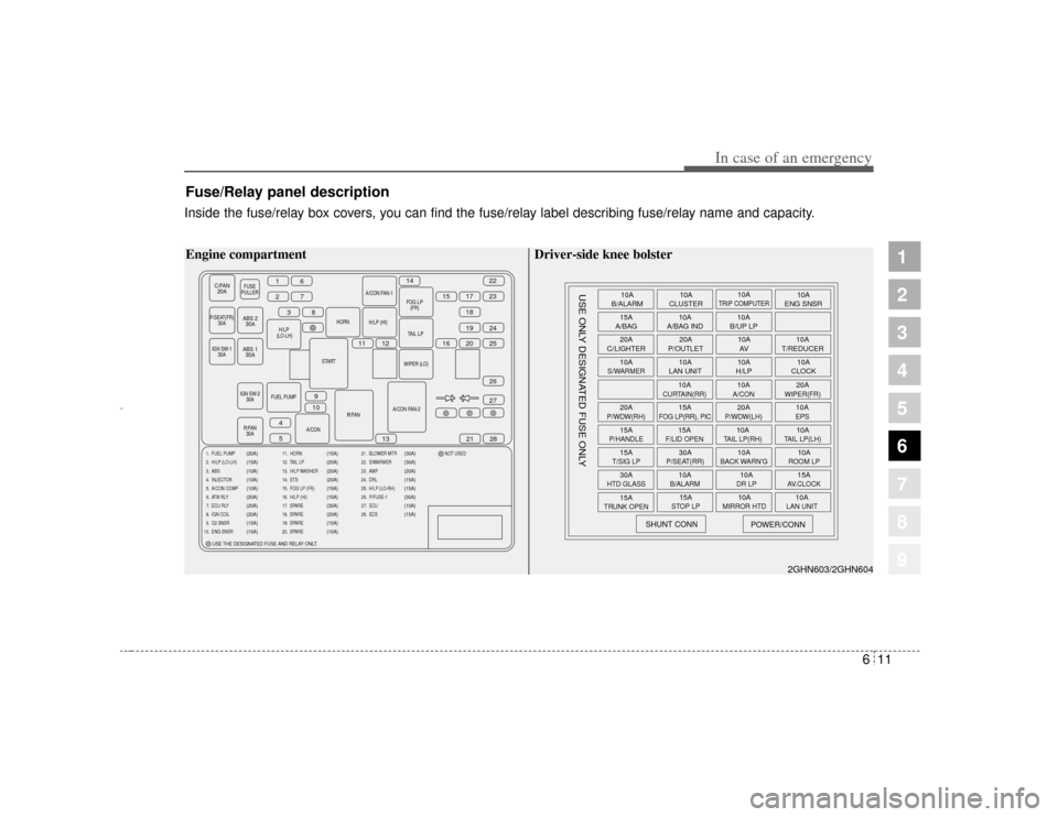
Fuse/Relay panel descriptionInside the fuse/relay box covers, you can find the fuse/relay label describing fuse/relay name and capacity.
C/FAN20A
FUSE
PULLER
P/SEAT(FR) 30A
H/
LP (LO-LH) HORN
START
IGN SW-2 30A
R/FAN 30A R/FAN
A/CON FAN-2WIPER (LO)
TAIL
LP
H/LP (HI)
A/CON FAN-1
FOG
LP(FR)
FUEL PUMP A/CON
16
2738
11 12 16 20
15
14
17
1822
23
19 25 24
27
21
13
9
10
4
5 28
26
IGN SW-1
30A
ABS 230A
ABS 1 30A
1. FUEL PUMP
2. H/LP (LO-LH)
3. ABS
4. INJECTOR
5. A/CON COMP
6. ATM RLY
7. ECU RLY
8. IGN COIL
9. O2 SNSR
10. ENG SNSR
(20A)
(15A)
(10A)
(10A)
(10A)
(20A)
(20A)
(20A)
(15A)
(15A)
11. HORN
12. TAIL LP
13. H/LP WASHER
14. ETS
15. FOG LP (FR)
16. H/LP (HI)
17. SPARE
18. SPARE
19. SPARE
20. SPARE
(15A)
(20A)
(20A)
(20A)
(15A)
(15A)
(30A)
(20A)
(15A)
(10A)
21. BLOWER MTR
22. S/WARMER
23. AMP
24. DRL
25. H/LP (LO-RH)
26. P/FUSE-1
27. ECU
28. ECS NOT USED
(30A)
(30A)
(20A)
(15A)
(15A)
(30A)
(10A)
(15A)
USE THE DESIGNATED FUSE AND RELAY ONLT.
Engine compartment
10A
B/ALARM
15A
A/BAG
20A
C/LIGHTER
10AS/WARMER20AP/WDW(RH)15AP/HANDLE15AT/SIG LP30AHTD GLASS15A
TRUNK OPEN
SHUNT CONN
USE ONLY DESIGNATED FUSE ONLY
POWER/CONN
15ASTOP LP
10A
MIRROR HTD
10ALAN UNIT
10AB/ALARM
10ADR LP
15AAV.CLOCK
30AP/SEAT(RR)
10A
BACK WARN'G
10AROOM LP
15AF/LID OPEN
10ATAIL LP(RH)
10ATAIL LP(LH)
15A
FOG LP(RR), PIC
20AP/WDW(LH)
10AEPS
10A
CURTAIN(RR)
10AA/CON
20AWIPER(FR)
10A
LAN UNIT 10A
H/LP 10A
CLOCK
20A
P/OUTLET 10A
T/REDUCER
10A
AV
10A
A/BAG IND 10A
B/UP LP
10A
CLUSTER 10A
ENG SNSR
10A
TRIP COMPUTER
2GHN603/2GHN604
Driver-side knee bolster
Opirus CAN 6-1.qxd 7/8/03 2:22 PM Page 11
Page 225 of 296
In case of an emergency12
6
1
2
3
4
5
6
7
8
9
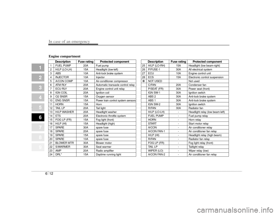
Description Fuse rating Protected component
1 FUEL PUMP 20A Fuel pump
2 H/LP (LO-LH) 15A Headlight (low-left)
3 ABS 10A Anti-lock brake system
4 INJECTOR 10A Injector
5 A/CON COMP 10A Air-conditioner compressor
6 ATM RLY 20A Automatic transaxle control relay
7 ECU RLY 20A Engine control unit relay
8 IGN COIL 20A Ignition coil
9 O2 SNSR 15A Oxygen sensor
10 ENG SNSR 15A
Power train control system sensors
11 HORN 15A Horn
12 TAIL LP 20A Tail light
13 H/LP WASHER 20A Headlight washer
14 ETS 20A Electronic throttle system
15 FOG LP (FR) 15A Fog light (front)
16 H/LP (HI) 15A Headlight (high)
17 SPARE 30A spare fuse
18 SPARE 20A spare fuse
19 SPARE 15A spare fuse
20 SPARE 10A spare fuse
21 BLOWER MTR 30A Blower motor
22 S/WARMER 30A Seat warmer
23 AMP 20A Radio amplifier
24 DRL* 15A Daytime running light
Description Fuse rating Protected component
25 H/LP (LO-RH) 15A Headlight (low beam-right)
26 P/FUSE-1 30A All electrical system
27 ECU 10A Engine control unit
28 ECS 15A Electronic control suspension
! NOT USED Not used
C/FAN 20A Condenser fan
P/SEAT (FR) 30A Power seat (front)
IGN SW-1 30A Ignition switch
ABS 2 30A Anti-lock brake system
ABS 1 30A Anti-lock brake system
IGN SW-2 30A Ignition switch
R/FAN 30A Radiator fan
H/LP (LO-LH) - Headlight relay (low beam-left)
FUEL PUMP - Fuel pump relay
HORN - Horn relay
START - Start motor relay
A/CON - Air conditioner relay
A/CON FAN-1 - Air conditioner fan relay
H/LP (HI) - Headlight relay (high beam)
R/FAN - Radiator fan relay
FOG LP (FR) - Fog light relay (front)
TAIL LP - Taillight relay
WIPER (LO) - Wiper relay (low)
A/CON FAN-2 - Air conditioner fan relay
Engine compartment
Opirus CAN 6-1.qxd 7/8/03 2:22 PM Page 12
Page 236 of 296
623
In case of an emergency
1
2
3
4
5
6
7
8
9
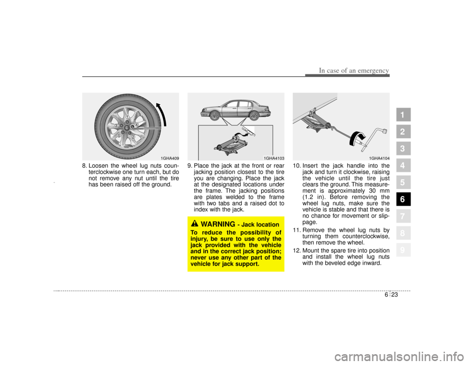
8. Loosen the wheel lug nuts coun-terclockwise one turn each, but do
not remove any nut until the tire
has been raised off the ground. 9. Place the jack at the front or rear
jacking position closest to the tire
you are changing. Place the jack
at the designated locations under
the frame. The jacking positions
are plates welded to the frame
with two tabs and a raised dot to
index with the jack. 10. Insert the jack handle into the
jack and turn it clockwise, raising
the vehicle until the tire just
clears the ground. This measure-
ment is approximately 30 mm
(1.2 in). Before removing the
wheel lug nuts, make sure the
vehicle is stable and that there is
no chance for movement or slip-
page.
11. Remove the wheel lug nuts by turning them counterclockwise,
then remove the wheel.
12. Mount the spare tire into position and install the wheel lug nuts
with the beveled edge inward.
WARNING
- Jack location
To reduce the possibility of
injury, be sure to use only the
jack provided with the vehicle
and in the correct jack position;
never use any other part of the
vehicle for jack support.
1GHA4104
1GHA4103
1GHA409
Opirus CAN 6-1.qxd 7/8/03 2:22 PM Page 23
Page 267 of 296
Maintenance30
7
1
2
3
4
5
6
7
8
9
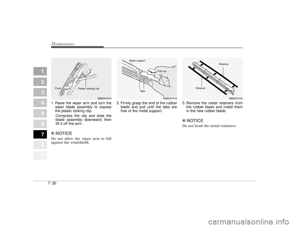
1. Raise the wiper arm and turn the
wiper blade assembly to expose
the plastic locking clip.
Compress the clip and slide the
blade assembly downward; then
lift it off the arm.✽ ✽ NOTICEDo not allow the wiper arm to fall
against the windshield.
2. Firmly grasp the end of the rubber
blade and pull until the tabs are
free of the metal support. 3. Remove the metal retainers from
the rubber blade and install them
in the new rubber blade.
✽ ✽NOTICEDo not bend the metal retainers.
MMSA7014
MMSA7015
MMSA7016
Plastic locking clip
Push
Tabs
Metal support
Pull out
RetainerRetainer
Opirus CAN 7-1.qxd 7/8/03 2:25 PM Page 30
Page 268 of 296
731
Maintenance
1
2
3
4
5
6
7
8
9
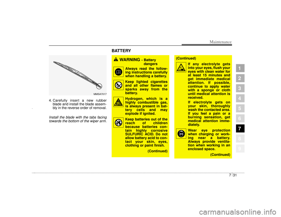
4. Carefully insert a new rubberblade and install the blade assem-
bly in the reverse order of removal.Install the blade with the tabs facingtowards the bottom of the wiper arm.
BATTERY
MMSA7017
WARNING
- Battery
dangers
Always read the follow-
ing instructions carefully
when handling a battery.
Keep lighted cigarettes and all other flames or
sparks away from the
battery.
Hydrogen, which is a highly combustible gas,
is always present in bat-
tery cells and may
explode if ignited.
Keep batteries out of the reach of children
because batteries con-
tain highly corrosive
SULFURIC ACID. Do not
allow battery acid to con-
tact your skin, eyes,
clothing or paint finish.
(Continued)
(Continued)If any electrolyte getsinto your eyes, flush your
eyes with clean water for
at least 15 minutes and
get immediate medical
attention. If possible,
continue to apply water
with a sponge or cloth
until medical attention is
received.
If electrolyte gets on
your skin, thoroughly
wash the contacted area.
If you feel a pain or a
burning sensation, get
medical attention imme-
diately.
Wear eye protection when charging or work-
ing near a battery.
Always provide ventila-
tion when working in an
enclosed space.
(Continued)
Opirus CAN 7-1.qxd 7/8/03 2:25 PM Page 31
Page 281 of 296
Maintenance44
7
1
2
3
4
5
6
7
8
9
Interior lights bulb replace-
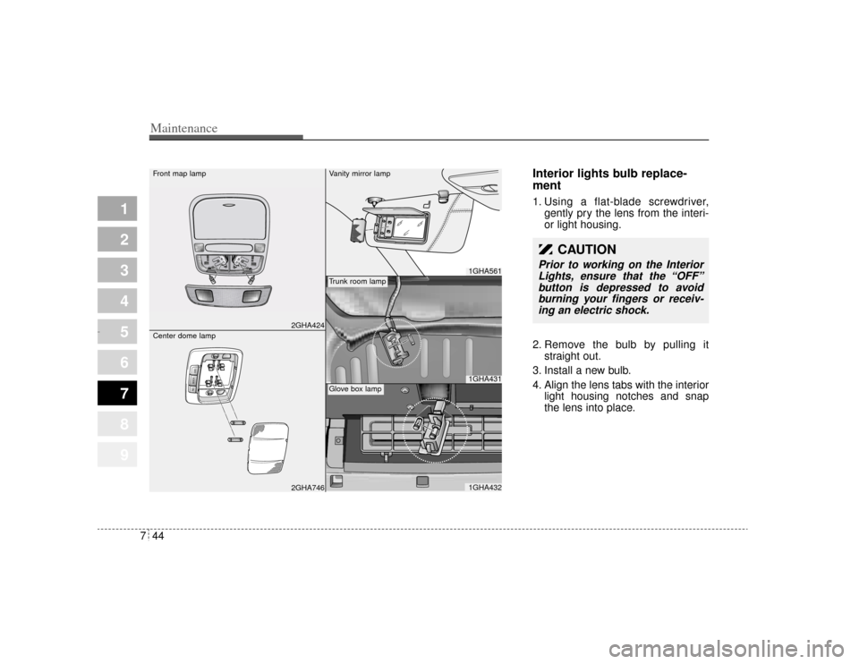
ment1. Using a flat-blade screwdriver,
gently pry the lens from the interi-
or light housing.
2. Remove the bulb by pulling it straight out.
3. Install a new bulb.
4. Align the lens tabs with the interior light housing notches and snap
the lens into place.
CAUTION
Prior to working on the InteriorLights, ensure that the “OFF”
button is depressed to avoid burning your fingers or receiv-ing an electric shock.
2GHA424
O FFDO ORON
2GHA746
1GHA5611GHA4311GHA432
Front map lamp
Center dome lamp
Vanity mirror lampTrunk room lampGlove box lamp
Opirus CAN 7-1.qxd 7/8/03 2:26 PM Page 44
Page 283 of 296
Maintenance46
7
1
2
3
4
5
6
7
8
9
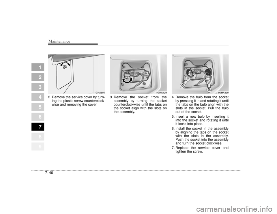
2. Remove the service cover by turn-
ing the plastic screw counterclock-
wise and removing the cover. 3. Remove the socket from the
assembly by turning the socket
counterclockwise until the tabs on
the socket align with the slots on
the assembly. 4. Remove the bulb from the socket
by pressing it in and rotating it until
the tabs on the bulb align with the
slots in the socket. Pull the bulb
out of the socket.
5. Insert a new bulb by inserting it into the socket and rotating it until
it locks into place.
6. Install the socket in the assembly by aligning the tabs on the socket
with the slots in the assembly.
Push the socket into the assembly
and turn the socket clockwise.
7. Replace the service cover and tighten the screw.
1GHA430
1GHA429
1GHA501
Opirus CAN 7-1.qxd 7/8/03 2:26 PM Page 46