power steering KIA AMANTI 2009 Owners Manual
[x] Cancel search | Manufacturer: KIA, Model Year: 2009, Model line: AMANTI, Model: KIA AMANTI 2009Pages: 321, PDF Size: 23.77 MB
Page 1 of 321
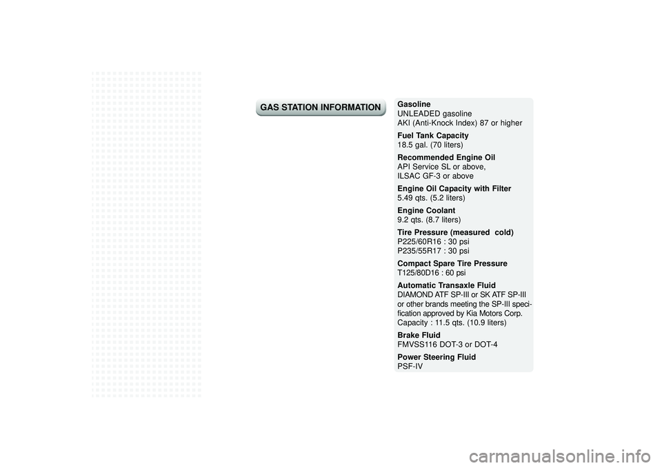
Gasoline
UNLEADED gasoline
AKI (Anti-Knock Index) 87 or higher
Fuel Tank Capacity
18.5 gal. (70 liters)
Recommended Engine Oil
API Service SL or above,
ILSAC GF-3 or above
Engine Oil Capacity with Filter
5.49 qts. (5.2 liters)
Engine Coolant
9.2 qts. (8.7 liters)
Tire Pressure (measured cold)
P225/60R16 : 30 psi
P235/55R17 : 30 psi
Compact Spare Tire PressureT125/80D16 : 60 psiAutomatic Transaxle FluidDIAMOND ATF SP-III or SK ATF SP-III
or other brands meeting the SP-III speci-
fication approved by Kia Motors Corp. Capacity : 11.5 qts. (10.9 liters)
Brake Fluid
FMVSS116 DOT-3 or DOT-4
Power Steering Fluid
PSF-IV
GAS STATION INFORMATION
Page 10 of 321
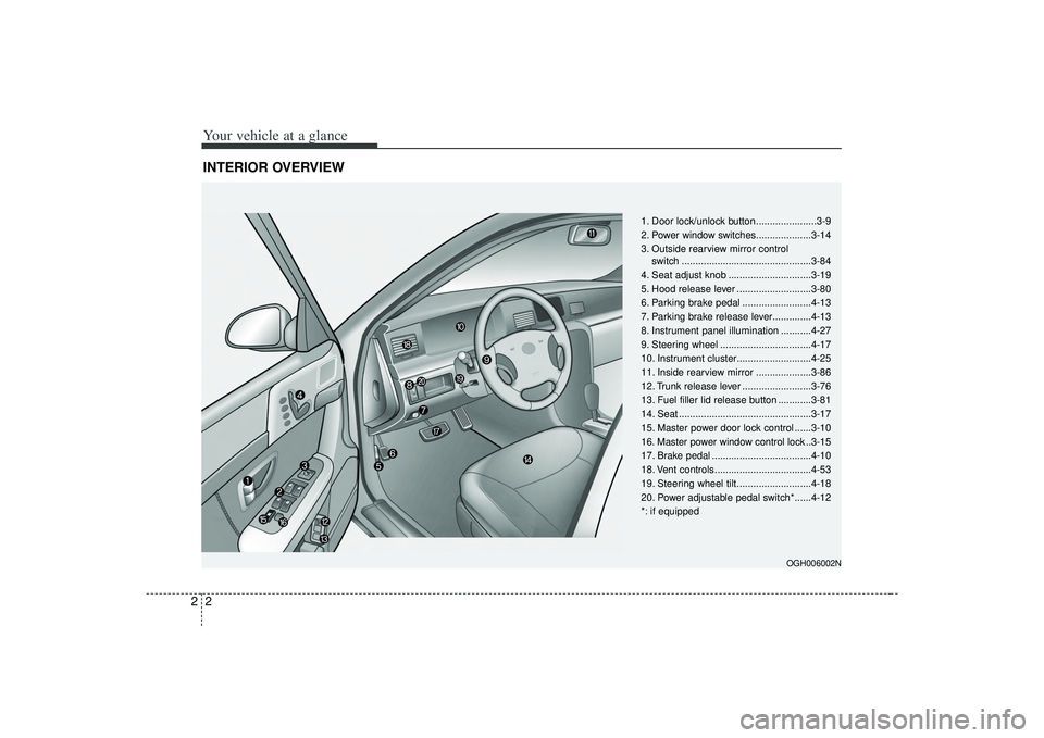
Your vehicle at a glance22INTERIOR OVERVIEW
OGH006002N
1. Door lock/unlock button ......................3-9
2. Power window switches....................3-14
3. Outside rearview mirror control switch ...............................................3-84
4. Seat adjust knob ..............................3-19
5. Hood release lever ...........................3-80
6. Parking brake pedal .........................4-13
7. Parking brake release lever..............4-13
8. Instrument panel illumination ...........4-27
9. Steering wheel .................................4-17
10. Instrument cluster...........................4-25
11. Inside rearview mirror ....................3-86
12. Trunk release lever .........................3-76
13. Fuel filler lid release button ............3-81
14. Seat ................................................3-17
15. Master power door lock control ......3-10
16. Master power window control lock ..3-15
17. Brake pedal ....................................4-10
18. Vent controls...................................4-53
19. Steering wheel tilt...........................4-18
20. Power adjustable pedal switch*......4-12
*: if equipped
Page 12 of 321
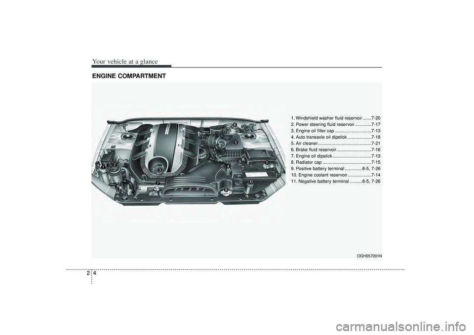
Your vehicle at a glance42ENGINE COMPARTMENT
OGH057001N
1. Windshield washer fluid reservoir .......7-20
2. Power steering fluid reservoir .............7-17
3. Engine oil filler cap .............................7-13
4. Auto transaxle oil dipstick ...................7-18
5. Air cleaner...........................................7-21
6. Brake fluid reservoir ............................7-16
7. Engine oil dipstick ...............................7-13
8. Radiator cap .......................................7-15
9. Positive battery terminal ..............6-5, 7-26
10. Engine coolant reservoir ...................7-14
11. Negative battery terminal ..........6-5, 7-26
Page 30 of 321
Knowing your vehicle18
3For a seating position more comfortable
to the driver and front passenger, adjust
the seat forward, backward, up and
down.
WARNING
Loose objects in the driver’s foot
area could interfere with the oper-
ation of the foot pedals, possibly
causing an accident. Loose
objects might interfere with the
seat slide mechanism. Do not
place anything under the front
seats.
The power seats are operable with the ignition OFF.
Therefore, children should never
be left unattended in the car.
WARNING
- Driver’s seat
Never attempt to adjust the seatwhile the vehicle is moving. This
could result in loss of control,
and an accident causing death,
serious injury, or property dam-
age.
with the normal position of the
seatback. Storing items against a
seatback or in any other way
interfering with proper locking of
a seatback could result in serious
or fatal injury in a sudden stop or
collision.
seatback upright and the lap por-
tion of the safety belt, or lap belt,
snug and low across the hips.
This position puts your safety
belts in the best position to pro-
tect you in case of an accident.
In order to avoid unnecessary air bag injuries including the possi-
bility of severe injury or death,
always sit as far back as possible
from the steering wheel so that
your chest is away at least 10
inches (250 mm) away from the
steering wheel.
CAUTION
Power seats are driven by electric motor. Stop operating when theadjustment is completed.
Excessive operation may damagethe electrical equipment.
When in operation, the power seats consume large amounts ofelectrical power. To preventunnecessary charging system drain, don’t adjust the powerseats longer than necessarywhile the engine is not running.
Do not operate two or more power seat control buttons at the sametime. Doing so may result inpower seat motor or electricalcomponent malfunction.
Page 67 of 321
355
Knowing your vehicle
Air bag system components The SRS air bag consists of the fol-lowing components;
1. Driver's air bag module
2. Passenger's air bag module
3. Side air bag module
4. Curtain air bag module
5. Front impact sensors
6. Side impact sensors
7. SRS air bag control module
8. Driver's seat position sensor
9. Occupant Classification System (Front passenger's seat only)
10. "PASSENGER AIR BAG OFF" indicator (Front passenger's seat
only)
11. Driver's and front passenger's safety belt buckle sensors
12. Retractor Pre-tensioner Assemblies
13. SRS "AIR BAG" warning light
A diagnostic system that continually monitors the system operation.
An indicator light to warn you of a pos- sible problem with the system.
Emergency power backup in case your car’s electrical system is disconnected
in a crash. The SRS uses a collection of sensors to
gather information about the driver’s seat
position, the driver’s and front passen-
ger’s safety belt usage and impact sever-
ity.
The driver’s seat position sensor, which
is installed on the seat track, determines
if the seat is fore or aft of a reference
position. Similarly, the safety belt usage
sensors determine if the driver and front
passenger’s safety belts are fastened.
These sensors provide the ability to con-
trol the SRS deployment based on how
close the driver’s seat is to the steering
wheel, how close the passenger’s seat is
to the instrument panel, whether or not
the safety belts are fastened, and the
severity of the impact.
(Continued)
If your vehicle has been subject-
ed to flood conditions (e.g.
soaked carpeting/standing water
on the floor of the vehicle, etc.) or
if your vehicle has become flood
damaged in any way, do not
attempt to start the vehicle or put
the key in the ignition before dis-
connecting the battery.
Disregarding this precaution may
cause air bag deployment, which
could result in serious personal
injury or death. If your vehicle is
subjected to flooded conditions,
before starting the vehicle, have
the vehicle towed to an author-
ized Kia dealer for inspection and
necessary repairs.
Page 153 of 321
417
Driving your vehicle
Power steeringPower Steering uses energy from the
engine to assist you in steering the vehi-
cle. If the engine is off or if the power
steering system becomes inoperative,
the vehicle may still be steered, but it will
require increased steering effort.
Should you notice any change in the
effort required to steer during normal
vehicle operation, have the power steer-
ing checked by an Authorized Kia Dealer.
✽ ✽NOTICE• Never hold the steering wheel against
a stop (extreme right or left turn) for
more than 5 seconds with the engine
running. Holding the steering wheel
for more than 5 seconds in either posi-
tion may cause damage to the power
steering pump.
• If the power steering drive belt breaks or if the power steering pump mal-
functions, the steering effort will
greatly increase.
✽ ✽ NOTICEIf the vehicle is parked for extended
periods outside in cold weather (below -
10 °C/14 °F), the power steering may
require increased effort when the engine
is first started. This is caused by
increased fluid viscosity due to the cold
weather and does not indicate a mal-
function.
When this happens, increase the engine
RPM by depressing the accelerator until
the RPM reaches 1,500 rpm then release
or let the engine idle for two or three
minutes to warm up the fluid.
STEERING WHEEL
Page 198 of 321
Driving tips65SUGGESTIONS FOR ECONOMICAL OPERATIONYour vehicle's fuel economy depends
mainly on your style of driving, where you
drive and when you drive.
Each of these factors affects how many
kilometers (miles) you can get from a liter
(gallon) of fuel. To operate your vehicle
as economically as possible, use the fol-
lowing driving suggestions to help save
money in both fuel and repairs:
Avoid lengthy warm-up idling. Once theengine is running smoothly, begin driv-
ing. Remember, engine warm-up may
take a little longer on cold days.
Save fuel by accelerating slowly after stopping.
Keep the engine in tune and follow the recommended periodic maintenance
schedule. This will increase the life of
all parts and lower your operating
costs. Do not use the air conditioner unnec-
essarily.
Slow down when driving on rough roads.
For longer tire life and better fuel econ- omy, always keep the tires inflated to
the recommended pressures.
Maintain a safe distance from other vehicles to avoid sudden stops. This
will reduce wear on brake linings and
pads. Driving in such a way will also
save fuel because extra fuel is required
to accelerate back to driving speed.
Do not carry unnecessary weight in the vehicle.
Do not rest your foot on the brake pedal while driving. This can cause
needless wear, possible damage to the
brakes, and poor fuel economy.
Improper wheel alignment results in faster tire wear and lower fuel econo-
my. Open windows at high speeds can
reduce fuel economy.
Fuel economy is less in crosswinds and headwinds. To help offset some of
this loss, slow down when driving in
these conditions.
Keeping a vehicle in good operating con-
dition is important both for economy and
safety. Therefore, have an authorized Kia
dealer perform scheduled inspections
and maintenance.
WARNING
- Engine off dur-
ing motion
Never turn the engine off to coast
down hills or anytime the vehicle is
in motion. The power steering and
power brakes will not function with-
out the engine running. Instead,
downshift to an appropriate gear for
engine braking effect.
Page 234 of 321
611
In case of an emergency
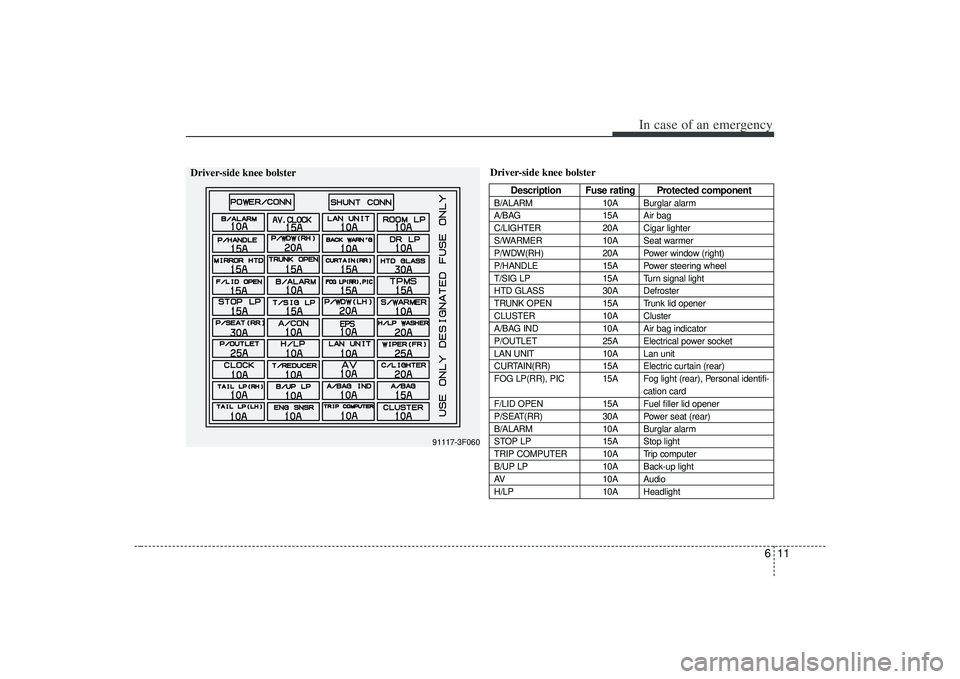
Driver-side knee bolster
Description Fuse rating Protected component
B/ALARM10A Burglar alarm
A/BAG 15A Air bag
C/LIGHTER 20A Cigar lighter
S/WARMER 10A Seat warmer
P/WDW(RH) 20A Power window (right)
P/HANDLE 15A Power steering wheel
T/SIG LP 15A Turn signal light
HTD GLASS 30A Defroster
TRUNK OPEN 15A Trunk lid opener
CLUSTER 10A Cluster
A/BAG IND 10A Air bag indicator
P/OUTLET 25A Electrical power socket
LAN UNIT 10A Lan unit
CURTAIN(RR) 15A Electric curtain (rear)
FOG LP(RR), PIC 15A Fog light (rear), Personal identifi- cation card
F/LID OPEN 15A Fuel filler lid opener
P/SEAT(RR) 30A Power seat (rear)
B/ALARM 10A Burglar alarm
STOP LP 15A Stop light
TRIP COMPUTER 10A Trip computer
B/UP LP 10A Back-up light
AV 10A Audio
H/LP 10A Headlight
91117-3F060
Driver-side knee bolster
Page 235 of 321

In case of an emergency12
6
Power connectorYour vehicle is equipped with a power connector to prevent bat-
tery discharge if your vehicle is parked without being operated
for prolonged periods. Use the following procedures before
parking the vehicle for prolonged period.
1. Turn off the engine.
2. Turn off the headlights and tail lights.
3. Open the driver-side knee bolster cover and pull up the
“POWER/CONN”.✽ ✽NOTICE• If the power connector is pulled up from the fuse panel, the
warning chime, AV system, clock and intetrior lamps, etc.,
will not operate. Some items must be reset after replace-
ment.
• Even though the power connector is pulled up, the battery can still be discharged by operation of the headlights or
other electrical devices.
Description Fuse rating Protected component
A/CON 10A Air-conditioning system
P/WDW(LH) 20A Power window (left)
TAIL LP(RH) 10A Taillight (right)
BACK WARN’G 10A Back warning
DR LP 10A Door courtesy lamp
MIRROR HTD 15A Outside review mirror defroster
ENG SNSR 10A
Power train control system sensors
T/REDUCER10A Seat belt tension reducer
CLOCK 10A Clock
WIPER(FR) 25A Wiper (front)
EPS 10A Electronic power steering
TAIL LP(LH) 10A Tail light (left)
ROOM LP 10A Room lamp
AV, CLOCK 15A Audio, Clock
LAN UNIT 10A Lan unit
TPMS 15A Tire pressure monitoring system
H/LP WASHER 20A Headlight washer
SHUNT CONN - Switch illumination
POWER/CONN - Power connector
1GHA403
Power
connector
Page 238 of 321
615
In case of an emergency
If towing service is not available in an
emergency, your vehicle may be tem-
porarily towed using a cable or chain
secured to the emergency towing hook
under the front or rear of the vehicle. Use
extreme caution when towing the vehicle.
A driver must be in the vehicle to steer it
and operate the brakes.
Towing in this manner may be done only
on hard-surfaced roads for a short dis-
tance and at low speeds. Also, the
wheels, axles, power train, steering and
brakes must all be in good condition.
Do not use the tow hooks to pull avehicle out of mud, sand or other con-
ditions from which the vehicle cannot
be driven out under its own power.
Avoid towing a vehicle heavier than the vehicle doing the towing.
The drivers of both vehicles should communicate with each other frequent-
ly. Before emergency towing, check that
the hook is not broken or damaged.
Fasten the towing cable or chain securely to the hook.
Do not jerk the hook. Apply steady and even force.
To avoid damaging the hook, do not pull from the side or at a vertical angle.
Always pull straight ahead.
CAUTION
Attach a towing strap to the tow hook.
Using a portion of the vehicle other than the tow hooks for tow-ing may damage the body of yourvehicle.
Use only a cable or chain specifi- cally intended for use in towingvehicles. Securely fasten the cable or chain to the towing hookprovided.
WARNING
Use extreme caution when towing
the vehicle.
Avoid sudden starts or erratic driving maneuvers which would
place excessive stress on the
emergency towing hook and tow-
ing cable or chain. The hook and
towing cable or chain may break
and cause serious injury or dam-
age.
If the towing vehicle can hardly move, do not forcibly continue
the towing. Contact an Authorized
Kia dealer or a commercial tow
truck service for assistance.
Tow the vehicle as straight ahead as possible.
Keep away from the vehicle dur- ing towing.