suspension KIA AMANTI 2009 Owners Manual
[x] Cancel search | Manufacturer: KIA, Model Year: 2009, Model line: AMANTI, Model: KIA AMANTI 2009Pages: 321, PDF Size: 23.77 MB
Page 203 of 321
511
Driving tips
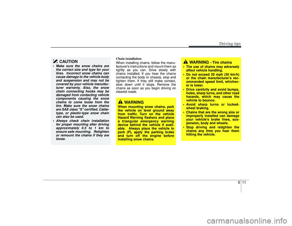
Chain installation
When installing chains, follow the manu-
facturer's instructions and mount them as
tightly as you can. Drive slowly with
chains installed. If you hear the chains
contacting the body or chassis, stop and
tighten them. If they still make contact,
slow down until it stops. Remove the
chains as soon as you begin driving on
cleared roads.
CAUTION
Make sure the snow chains arethe correct size and type for yourtires. Incorrect snow chains cancause damage to the vehicle body and suspension and may not becovered by your vehicle manufac-turer warranty. Also, the snow chain connecting hooks may bedamaged from contacting vehiclecomponents causing the snowchains to come loose from the tire. Make sure the snow chainsare SAE class “S” certified. Cable-type, or plastic-type snow chain can also be used.
Always check chain installation for proper mounting after drivingapproximately 0.5 to 1 km to ensure safe mounting. Retightenor remount the chains if they areloose.
WARNING
When mounting snow chains, park
the vehicle on level ground away
from traffic. Turn on the vehicle
Hazard Warning flashers and place
a triangular emergency warning
device behind the vehicle if avail-
able. Always place the vehicle in
park (P), apply the parking brake
and turn off the engine before
installing snow chains.
WARNING
- Tire chains
The use of chains may adversely affect vehicle handling.
Do not exceed 20 mph (30 km/h) or the chain manufacturer’s rec-
ommended speed limit, whichev-
er is lower.
Drive carefully and avoid bumps, holes, sharp turns, and other road
hazards, which may cause the
vehicle to bounce.
Avoid sharp turns or locked- wheel braking.
Chains that are the wrong size or improperly installed can damage
your vehicle's brake lines, sus-
pension, body and wheels.
Stop driving and retighten the chains any time you hear them
hitting the vehicle.
Page 208 of 321
Driving tips16
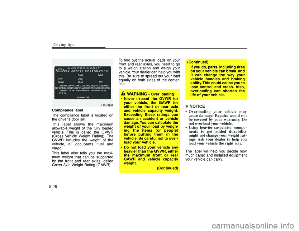
5Compliance label
The compliance label is located on
the driver's door sill.
This label shows the maximum
allowable weight of the fully loaded
vehicle. This is called the GVWR
(Gross Vehicle Weight Rating). The
GVWR includes the weight of the
vehicle, all occupants, fuel and
cargo.
This label also tells you the maxi-
mum weight that can be supported
by the front and rear axles, called
Gross Axle Weight Rating (GAWR). To find out the actual loads on your
front and rear axles, you need to go
to a weigh station and weigh your
vehicle. Your dealer can help you with
this. Be sure to spread out your load
equally on both sides of the center-
line.
✽ ✽
NOTICE• Overloading your vehicle may
cause damage. Repairs would not
be covered by your warranty. Do
not overload your vehicle.
• Using heavier suspension compo- nents to get added durability
might not change your weight rat-
ings. Ask your dealer to help you
load your vehicle the right way.The label will help you decide how
much cargo and installed equipment
your vehicle can carry.
1JBN5901
WARNING
- Over loading
Never exceed the GVWR for your vehicle, the GAWR for
either the front or rear axle
and vehicle capacity weight.
Exceeding these ratings can
cause an accident or vehicle
damage. You can calculate the
weight of your load by weigh-
ing the items (or people)
before putting them in the
vehicle. Be careful not to over-
load your vehicle.
Do not load your vehicle any heavier than the GVWR, either
the maximum front or rear
GAWR and vehicle capacity
weight.
(Continued)
(Continued)If you do, parts, including tires
on your vehicle can break, and
it can change the way your
vehicle handles and braking
ability. This could cause you to
lose control and crash. Also,
overloading can shorten the
life of your vehicle.
Page 233 of 321
In case of an emergency10
6
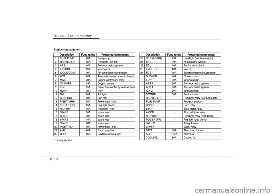
Description Fuse rating Protected component
1 FUEL PUMP 20A Fuel pump
2 H/LP (LO-LH) 15A Headlight (low-left)
3 ABS 10A Anti-lock brake system
4 IGN COIL 15A Ignition coil
5 A/CON COMP 10A Air-conditioner compressor
6 ATM 20A Automatic transaxle control relay
7 MAIN 20A Engine control unit relay
8 O2 SNSR 15A Oxygen sensor
9 EGR 15A
Power train control system sensors
10 HORN 15A Horn
11 TAIL 20A Tail light
12 SUNROOF 20A Sun roof
13 P/SEAT (RH) 20A Power seat (right)
14 FOG LP (FR) 15A Fog light (front)
15 H/LP (HI) 15A Headlight (high)
16 SPARE 30A spare fuse
17 SPARE 20A spare fuse
18 SPARE 15A spare fuse
19 SPARE 10A spare fuse
20 P/SEAT (LH) 30A Power seat (left)
21 AMP 20A Radio amplifier
22 DRL* 15A Daytime running lightEngine compartment
Description Fuse rating Protected component
23 H/LP (LO-RH) 15A Headlight (low beam-right)
24 I/P B+ 30A All electrical system
25 ECU 10A Engine control unit
26 INJECTOR 10A Injector
27 ECS * 15A Electronic control suspension
BLOWER 40A Blower motor
IGN 1 30A Ignition switch
ABS 2 30A Anti-lock brake system
ABS 1 30A Anti-lock brake system
IGN 2 30A Ignition switch
S/WARM 30A Seat warmer
H/LP (LO-LH) - Headlight relay (low beam-left)
FUEL PUMP - Fuel pump relay
HORN - Horn relay
START - Start motor relay
A/CON - Air conditioner relay
H/LP (HI) - Headlight relay (high beam)
FOG LP (FR) - Fog light relay (front)
TAIL LP - Taillight relay
WIPER - Wiper relay
BATT 60A Alternator, Battery
ALT 150A Alternator
COOLING 60A Cooling fan
* : if equipped
Page 255 of 321
75
Maintenance
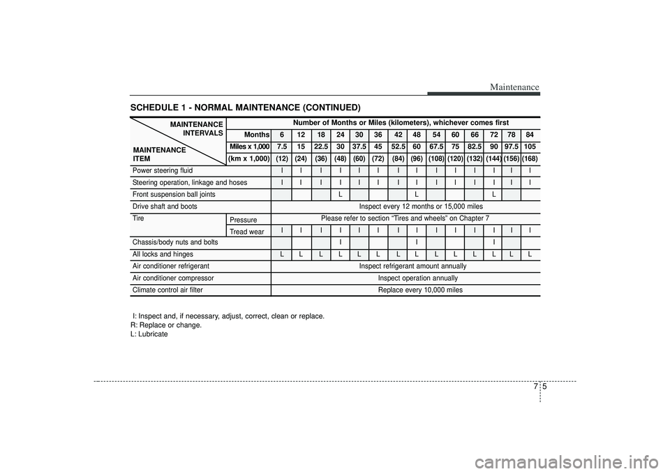
SCHEDULE 1 - NORMAL MAINTENANCE (CONTINUED)
MAINTENANCEINTERVALS
MAINTENANCE
ITEM
Number of Months or Miles (kilometers), whichever comes first
Months 6 12 18 24 30 36 42 48 54 60 66 72 78 84
Miles x 1,000 7.5 15 22.5 30 37.5 45 52.5 60 67.5 75 82.5 90 97.5 105
(km x 1,000)
(12) (24) (36) (48) (60) (72) (84) (96) (108) (120) (132) (144) (156) (168)
Power steering fluid I I I I I I I I I I I I I I
Steering operation, linkage and hoses I I I I I I I I I I I I I I
Front suspension ball joints L L L
Drive shaft and boots Inspect every 12 months or 15,000 miles
Tire Please refer to section “Tires and wheels” on Chapter 7 II I III II II I III
Chassis/body nuts and bolts I I I
All locks and hinges L L L L L L L L L L L L L L
Air conditioner refrigerant Inspect refrigerant amount annually
Air conditioner compressor Inspect operation annually
Climate control air filter Replace every 10,000 miles
I: Inspect and, if necessary, adjust, correct, clean or replace.
R: Replace or change.
L: Lubricate
Pressure
Tread wear
Page 258 of 321
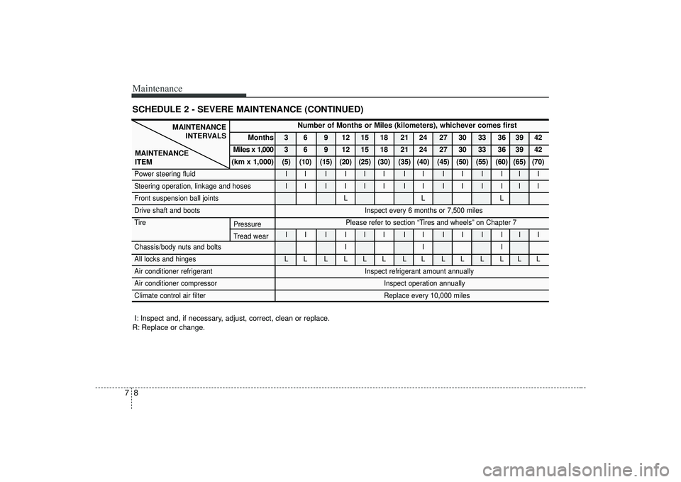
Maintenance87SCHEDULE 2 - SEVERE MAINTENANCE (CONTINUED)
MAINTENANCEINTERVALS
MAINTENANCE
ITEM
Number of Months or Miles (kilometers), whichever comes first
Months 3 6 9 12 15 18 21 24 27 30 33 36 39 42
Miles x 1,000 3 6 9 12 15 18 21 24 27 30 33 36 39 42
(km x 1,000)
(5) (10) (15) (20) (25) (30) (35) (40) (45) (50) (55) (60) (65) (70)
Power steering fluid I I I I I I I I I I I I I I
Steering operation, linkage and hoses I I I I I I I I I I I I I I
Front suspension ball joints L L L
Drive shaft and boots Inspect every 6 months or 7,500 miles
Tire Please refer to section “Tires and wheels” on Chapter 7 II I III II II I III
Chassis/body nuts and bolts I I I
All locks and hinges L L L L L L L L L L L L L L
Air conditioner refrigerant Inspect refrigerant amount annually
Air conditioner compressor Inspect operation annually
Climate control air filter Replace every 10,000 miles
I: Inspect and, if necessary, adjust, correct, clean or replace.
R: Replace or change.
Pressure
Tread wear