audio KIA CADENZA 2017 Owners Manual
[x] Cancel search | Manufacturer: KIA, Model Year: 2017, Model line: CADENZA, Model: KIA CADENZA 2017Pages: 500, PDF Size: 10.37 MB
Page 15 of 500
25
Your vehicle at a glance
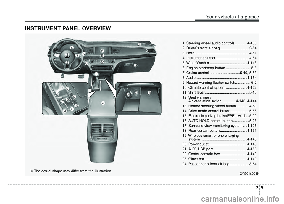
INSTRUMENT PANEL OVERVIEW
1. Steering wheel audio controls ............4-155
2. Driver`s front air bag .............................3-54
3. Horn ......................................................4-51
4. Instrument cluster .................................4-64
5. Wiper/Washer .....................................4-113
6. Engine start/stop button .........................5-6
7. Cruise control ..............................5-49, 5-53
8. Audio...................................................4-154
9. Hazard warning flasher switch................6-2
10. Climate control system .....................4-122
11. Shift lever ............................................5-10
12. Seat warmer /Air ventilation switch ..............4-142, 4-144
13. Heated steering wheel button.............4-50
14. Drive mode control button ..................5-68
15. Electronic parking brake(EPB) switch... 5-20
16. AUTO HOLD control button ................5-26
17. Surround view monitoring system ....4-105
18. Rear curtain button ...........................4-151
19. Wireless smart phone charging system ..............................................4-146
20. Power outlet ......................................4-145
21. AUX, USB port..................................4-156
22. Center console box...........................4-140
23. Glove box ..........................................4-140
24. Passenger`s front air bag ...................3-54
OYG016004N❈ The actual shape may differ from the illustration.
Page 85 of 500
Interior features . . . . . . . . . . . . . . . . . . . . . . . . . . 4-142
• Cup holder . . . . . . . . . . . . . . . . . . . . . . . . . . . . . . . . . 4-142
• Seat warmer . . . . . . . . . . . . . . . . . . . . . . . . . . . . . . . . 4-142
• Air ventilation seat . . . . . . . . . . . . . . . . . . . . . . . . . . 4-144
• Sunvisor . . . . . . . . . . . . . . . . . . . . . . . . . . . . . . . . . . . 4-\
144
• Power outlet . . . . . . . . . . . . . . . . . . . . . . . . . . . . . . . . 4-145
• Wireless smart phone charging system . . . . . . . . . . 4-146
• Clothes hanger . . . . . . . . . . . . . . . . . . . . . . . . . . . . . . 4-149
• Floor mat anchor (s) . . . . . . . . . . . . . . . . . . . . . . . . . 4-150
• Side curtain . . . . . . . . . . . . . . . . . . . . . . . . . . . . . . . . 4-151
• Rear curtain . . . . . . . . . . . . . . . . . . . . . . . . . . . . . . . . 4-151
• Clock . . . . . . . . . . . . . . . . . . . . . . . . . . . . . . . . . . . . \
. . 4-152
• Luggage net (Holder) . . . . . . . . . . . . . . . . . . . . . . . . 4-153
Audio system . . . . . . . . . . . . . . . . . . . . . . . . . . . . . 4-154
• Antenna. . . . . . . . . . . . . . . . . . . . . . . . . . . . . . . 4-154
• Steering wheel audio controls. . . . . . . . . . . . . . . . . . 4-155
• AUX, USB port . . . . . . . . . . . . . . . . . . . . . . . . . . . . . 4-156
4
Page 185 of 500
Features of your vehicle
104
4
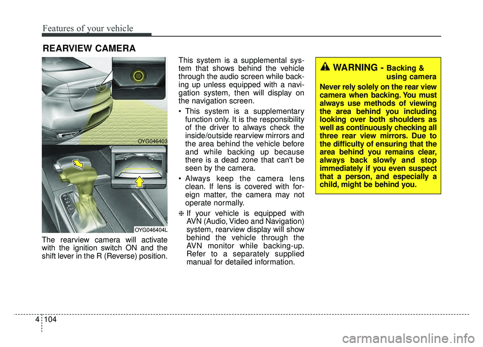
The rearview camera will activate
with the ignition switch ON and the
shift lever in the R (Reverse) position. This system is a supplemental sys-
tem that shows behind the vehicle
through the audio screen while back-
ing up unless equipped with a navi-
gation system, then will display on
the navigation screen.
This system is a supplementary
function only. It is the responsibility
of the driver to always check the
inside/outside rearview mirrors and
the area behind the vehicle before
and while backing up because
there is a dead zone that can't be
seen by the camera.
Always keep the camera lens clean. If lens is covered with for-
eign matter, the camera may not
operate normally.
❈If your vehicle is equipped with
AVN (Audio, Video and Navigation)
system, rearview display will show
behind the vehicle through the
AVN monitor while backing-up.
Refer to a separately supplied
manual for detailed information.
REARVIEW CAMERA
WARNING - Backing &
using camera
Never rely solely on the rear view
camera when backing. You must
always use methods of viewing
the area behind you including
looking over both shoulders as
well as continuously checking all
three rear view mirrors. Due to
the difficulty of ensuring that the
area behind you remains clear,
always back slowly and stop
immediately if you even suspect
that a person, and especially a
child, might be behind you.
OYG046403
OYG046404L
Page 226 of 500
4145
Features of your vehicle
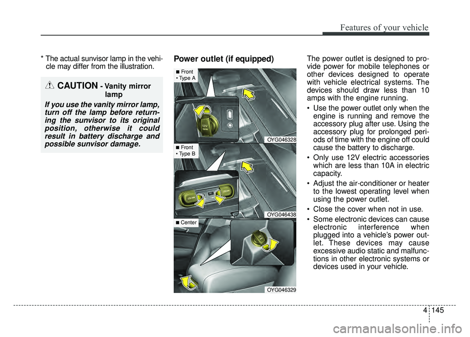
* The actual sunvisor lamp in the vehi-cle may differ from the illustration.Power outlet (if equipped)The power outlet is designed to pro-
vide power for mobile telephones or
other devices designed to operate
with vehicle electrical systems. The
devices should draw less than 10
amps with the engine running.
Use the power outlet only when the
engine is running and remove the
accessory plug after use. Using the
accessory plug for prolonged peri-
ods of time with the engine off could
cause the battery to discharge.
Only use 12V electric accessories which are less than 10A in electric
capacity.
Adjust the air-conditioner or heater to the lowest operating level when
using the power outlet.
Close the cover when not in use.
Some electronic devices can cause electronic interference when
plugged into a vehicle’s power out-
let. These devices may cause
excessive audio static and malfunc-
tions in other electronic systems or
devices used in your vehicle.
CAUTION- Vanity mirror
lamp
If you use the vanity mirror lamp,turn off the lamp before return-ing the sunvisor to its originalposition, otherwise it couldresult in battery discharge andpossible sunvisor damage.
OYG046328
OYG046438
OYG046329
■Front
■Front
■ Center
Page 233 of 500
Features of your vehicle
152
4
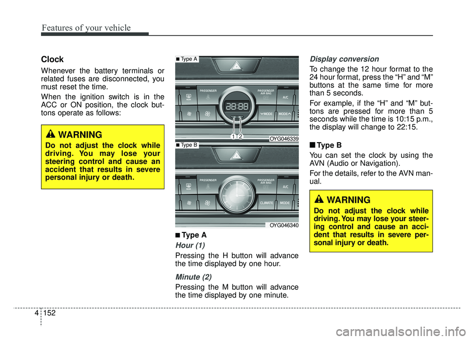
Clock
Whenever the battery terminals or
related fuses are disconnected, you
must reset the time.
When the ignition switch is in the
ACC or ON position, the clock but-
tons operate as follows:
■ ■
Type A
Hour (1)
Pressing the H button will advance
the time displayed by one hour.
Minute (2)
Pressing the M button will advance
the time displayed by one minute.
Display conversion
To change the 12 hour format to the
24 hour format, press the “H” and “M”
buttons at the same time for more
than 5 seconds.
For example, if the “H” and “M” but-
tons are pressed for more than 5
seconds while the time is 10:15 p.m.,
the display will change to 22:15.
■ ■ Type B
You can set the clock by using the
AVN (Audio or Navigation).
For the details, refer to the AVN man-
ual.
■Type A
OYG046339
OYG046340
■Type B
WARNING
Do not adjust the clock while
driving. You may lose your steer-
ing control and cause an acci-
dent that results in severe per-
sonal injury or death.
WARNING
Do not adjust the clock while
driving. You may lose your
steering control and cause an
accident that results in severe
personal injury or death.
Page 235 of 500
Features of your vehicle
154
4
✽
✽
NOTICE
If you install an after market HID
head lamp, your vehicle’s audio and
electronic device may malfunction.
❈ If your vehicle is equipped with
AVN(Audio, Video and Navigation)
system, refer to a separately sup-
plied manual for detailed informa-
tion.
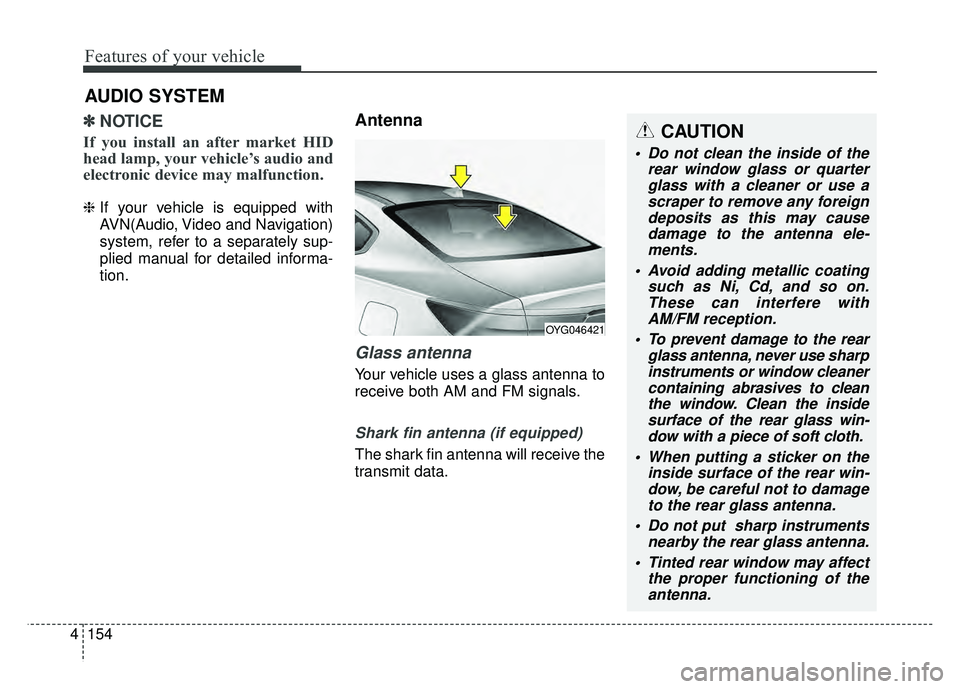
Antenna
Glass antenna
Your vehicle uses a glass antenna to
receive both AM and FM signals.
Shark fin antenna (if equipped)
The shark fin antenna will receive the
transmit data.
AUDIO SYSTEM
OYG046421
CAUTION
Do not clean the inside of the
rear window glass or quarterglass with a cleaner or use ascraper to remove any foreigndeposits as this may causedamage to the antenna ele-ments.
Avoid adding metallic coating such as Ni, Cd, and so on.These can interfere withAM/FM reception.
To prevent damage to the rear glass antenna, never use sharpinstruments or window cleanercontaining abrasives to cleanthe window. Clean the insidesurface of the rear glass win-dow with a piece of soft cloth.
When putting a sticker on the inside surface of the rear win-dow, be careful not to damageto the rear glass antenna.
Do not put sharp instruments nearby the rear glass antenna.
Tinted rear window may affect the proper functioning of theantenna.
Page 236 of 500
4155
Features of your vehicle
Steering wheel audio controls
(if equipped)
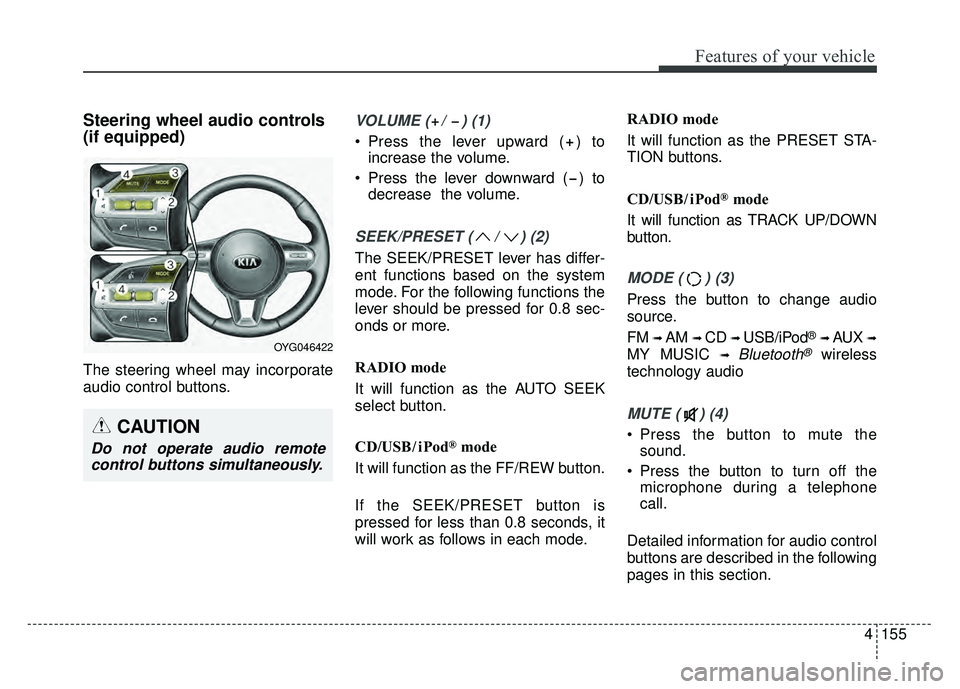
The steering wheel may incorporate
audio control buttons.
VOLUME ( / ) (1)
Press the lever upward ( ) toincrease the volume.
Press the lever downward ( ) to decrease the volume.
SEEK/PRESET ( / ) (2)
The SEEK/PRESET lever has differ-
ent functions based on the system
mode. For the following functions the
lever should be pressed for 0.8 sec-
onds or more.
RADIO mode
It will function as the AUTO SEEK
select button.
CD/USB/ iPod
®mode
It will function as the FF/REW button.
If the SEEK/PRESET button is
pressed for less than 0.8 seconds, it
will work as follows in each mode. RADIO mode
It will function as the PRESET STA-
TION buttons.
CD/USB/ iPod
®mode
It will function as TRACK UP/DOWN
button.
MODE ( ) (3)
Press the button to change audio
source.
FM
➟ AM ➟ CD ➟ USB/iPod®➟ AUX ➟
MY MUSIC ➟ Bluetooth®wireless
technology audio
MUTE ( ) (4)
Press the button to mute the sound.
Press the button to turn off the microphone during a telephone
call.
Detailed information for audio control
buttons are described in the following
pages in this section.CAUTION
Do not operate audio remote control buttons simultaneously.
OYG046422
Page 237 of 500
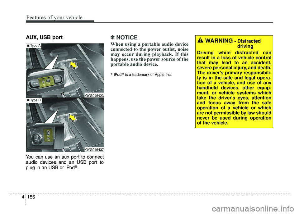
AUX, USB port
You can use an aux port to connect
audio devices and an USB port to
plug in an USB or iPod
®.
✽ ✽NOTICE
When using a portable audio device
connected to the power outlet, noise
may occur during playback. If this
happens, use the power source of the
portable audio device.
*iPod®is a trademark of Apple Inc.
OYG046437
OYG046423
■Type A
■Type B
WARNING- Distracted
driving
Driving while distracted can
result in a loss of vehicle control
that may lead to an accident,
severe personal injury, and death.
The driver's primary responsibili-
ty is in the safe and legal opera-
tion of a vehicle, and use of any
handheld devices, other equip-
ment, or vehicle systems which
take the driver's eyes, attention
and focus away from the safe
operation of a vehicle or which
are not permissible by law should
never be used during operation
of the vehicle.
4156
Features of your vehicle
Page 432 of 500

761
Maintenance
Fuse switch
Always set the fuse switch to the ON
position before using the vehicle.
If you move the switch to the OFF
position, some items such as audio
and digital clock must be reset and
transmitter (or smart key) may not
work properly. When the switch is
Off, the caution indicator will be dis-
played on the instrument cluster.
Always place the fuse switch in the
ON position while driving the vehicle.
If the switch is located in the “OFF”
position, a caution indicator will be
displayed in the cluster.
Engine compartment fuse
replacement
1. Turn the ignition switch and allother switches off.
2. Remove the fuse panel cover by pressing the tab and pulling the
cover up. When the blade type
fuse is disconnected, remove it by
using the clip designed for chang-
ing fuses located in the engine
compartment fuse box. Upon
removal, securely insert reserve
fuse of the same rating. 3. Check the removed fuse; replace it
if it is blown. To remove or insert
the fuse, use the fuse puller in the
engine compartment fuse panel.
4. Push in a new fuse of the same rating, and make sure it fits tightly
in the clips. If it fits loosely, consult
an authorized Kia dealer.
CAUTION
After checking the fuse panel inthe engine compartment,securely install the fuse panelcover through the audible click-ing sound.
If not, electrical failures mayoccur from water contact.
OYG076030
OYG076031
Page 436 of 500
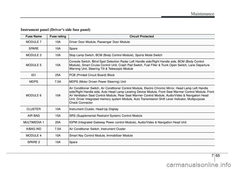
765
Maintenance
Fuse NameFuse ratingCircuit Protected
MODULE 710ADriver Door Module, Passenger Door Module
SPARE10ASpare
MODULE 310AStop Lamp Switch, BCM (Body Control Module), Sports Mode Switch
MODULE 510AConsole Switch, Blind Spot Detection Radar Left Handle side/Right Handle\
side, BCM (Body Control
Module), Smart Cruise Control Unit, Crash Pad Switch, Fuel Filler & Trunk Open Switch, Lane Departure
Warning Unit, Steering Tilt & Telescopic Module
IG125APCB (Printed Circuit Board) Block
MDPS7.5AMDPS (Motor Driven Power Steering) Unit
MODULE 610A
Air Conditioner Switch, Air Conditioner Control Module, Electro Chromic Mirror, Head Lamp Left Handle
side/Right Handle side, Auto Head Lamp Leveling Device Module, Front Seat Warmer Control Module, Front
Air Ventilation Seat Control Module, Rear Seat Warmer Control Module, Audio/Video & Navigation Head
Unit, Driver Integrated memory system Module, Auto Transmission Shift Lever Indicator, Multipurpose
Check Connector
CLUSTER10AInstrument Cluster, Head-Up Display
AIR BAG15ASRS (Supplemental Restraint System) Control Module
MULTIMEDIA 120AIGPM (Integrated Gateway Power control Module), Audio/Video & Navigation Head Unit
A/BAG IND7.5AAir Conditioner Switch, Instrument Cluster
MODULE 410ASmart Key Control Module, Immobilizer Module
SPARE 210ASpare
Instrument panel (Driver’s side fuse panel)