clock KIA CADENZA 2017 Owners Manual
[x] Cancel search | Manufacturer: KIA, Model Year: 2017, Model line: CADENZA, Model: KIA CADENZA 2017Pages: 500, PDF Size: 10.37 MB
Page 85 of 500
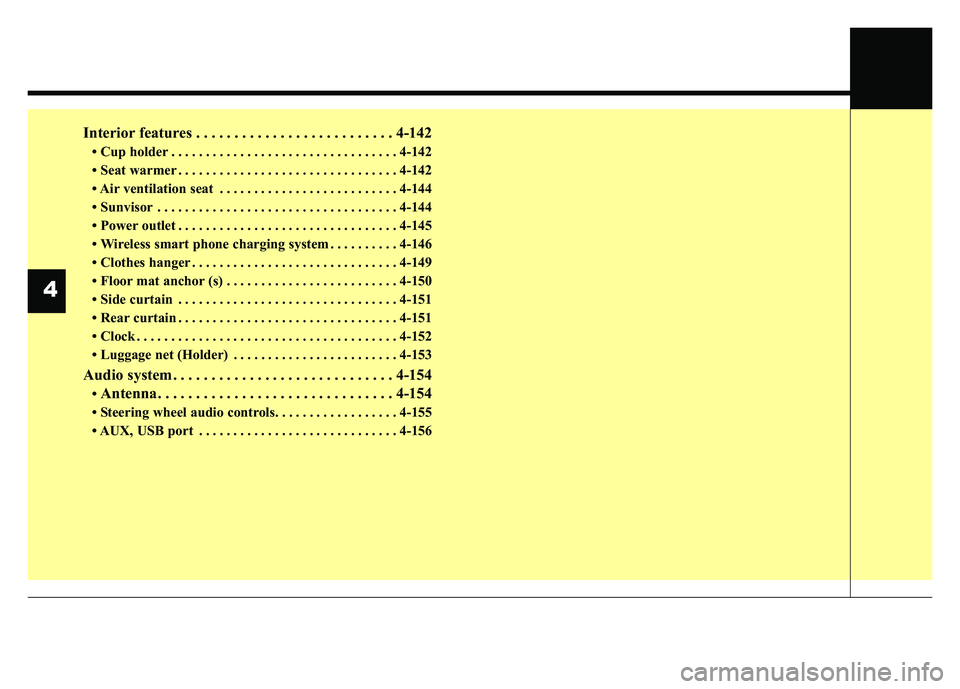
Interior features . . . . . . . . . . . . . . . . . . . . . . . . . . 4-142
• Cup holder . . . . . . . . . . . . . . . . . . . . . . . . . . . . . . . . . 4-142
• Seat warmer . . . . . . . . . . . . . . . . . . . . . . . . . . . . . . . . 4-142
• Air ventilation seat . . . . . . . . . . . . . . . . . . . . . . . . . . 4-144
• Sunvisor . . . . . . . . . . . . . . . . . . . . . . . . . . . . . . . . . . . 4-\
144
• Power outlet . . . . . . . . . . . . . . . . . . . . . . . . . . . . . . . . 4-145
• Wireless smart phone charging system . . . . . . . . . . 4-146
• Clothes hanger . . . . . . . . . . . . . . . . . . . . . . . . . . . . . . 4-149
• Floor mat anchor (s) . . . . . . . . . . . . . . . . . . . . . . . . . 4-150
• Side curtain . . . . . . . . . . . . . . . . . . . . . . . . . . . . . . . . 4-151
• Rear curtain . . . . . . . . . . . . . . . . . . . . . . . . . . . . . . . . 4-151
• Clock . . . . . . . . . . . . . . . . . . . . . . . . . . . . . . . . . . . . \
. . 4-152
• Luggage net (Holder) . . . . . . . . . . . . . . . . . . . . . . . . 4-153
Audio system . . . . . . . . . . . . . . . . . . . . . . . . . . . . . 4-154
• Antenna. . . . . . . . . . . . . . . . . . . . . . . . . . . . . . . 4-154
• Steering wheel audio controls. . . . . . . . . . . . . . . . . . 4-155
• AUX, USB port . . . . . . . . . . . . . . . . . . . . . . . . . . . . . 4-156
4
Page 118 of 500
437
Features of your vehicle
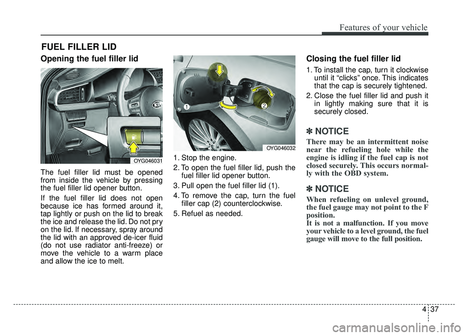
Opening the fuel filler lid
The fuel filler lid must be opened
from inside the vehicle by pressing
the fuel filler lid opener button.
If the fuel filler lid does not open
because ice has formed around it,
tap lightly or push on the lid to break
the ice and release the lid. Do not pry
on the lid. If necessary, spray around
the lid with an approved de-icer fluid
(do not use radiator anti-freeze) or
move the vehicle to a warm place
and allow the ice to melt.1. Stop the engine.
2. To open the fuel filler lid, push the
fuel filler lid opener button.
3. Pull open the fuel filler lid (1).
4. To remove the cap, turn the fuel filler cap (2) counterclockwise.
5. Refuel as needed.
Closing the fuel filler lid
1. To install the cap, turn it clockwise until it “clicks” once. This indicates
that the cap is securely tightened.
2. Close the fuel filler lid and push it in lightly making sure that it is
securely closed.
✽ ✽NOTICE
There may be an intermittent noise
near the refueling hole while the
engine is idling if the fuel cap is not
closed securely. This occurs normal-
ly with the OBD system.
✽ ✽NOTICE
When refueling on unlevel ground,
the fuel gauge may not point to the F
position.
It is not a malfunction. If you move
your vehicle to a level ground, the fuel
gauge will move to the full position.
FUEL FILLER LID
OYG046031
OYG046032
Page 203 of 500
Features of your vehicle
122
4
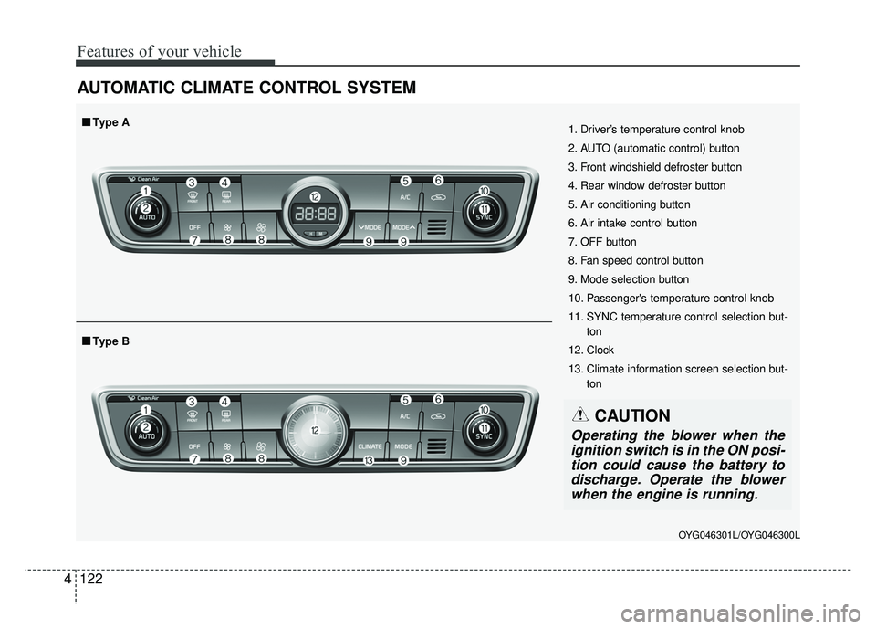
AUTOMATIC CLIMATE CONTROL SYSTEM
OYG046301L/OYG046300L
1. Driver’s temperature control knob
2. AUTO (automatic control) button
3. Front windshield defroster button
4. Rear window defroster button
5. Air conditioning button
6. Air intake control button
7. OFF button
8. Fan speed control button
9. Mode selection button
10. Passenger's temperature control knob
11. SYNC temperature control selection but-
ton
12. Clock
13. Climate information screen selection but- ton
■
■Type B
■
■Type A
CAUTION
Operating the blower when the
ignition switch is in the ON posi-tion could cause the battery todischarge. Operate the blowerwhen the engine is running.
Page 233 of 500
Features of your vehicle
152
4
Clock
Whenever the battery terminals or
related fuses are disconnected, you
must reset the time.
When the ignition switch is in the
ACC or ON position, the clock but-
tons operate as follows:
■ ■
Type A
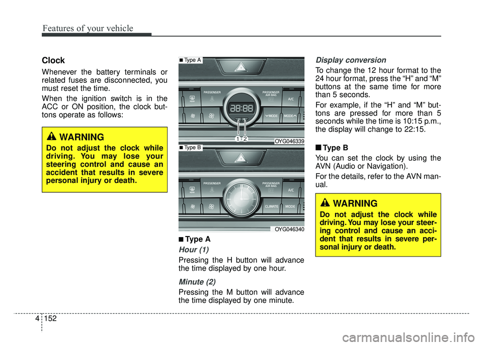
Hour (1)
Pressing the H button will advance
the time displayed by one hour.
Minute (2)
Pressing the M button will advance
the time displayed by one minute.
Display conversion
To change the 12 hour format to the
24 hour format, press the “H” and “M”
buttons at the same time for more
than 5 seconds.
For example, if the “H” and “M” but-
tons are pressed for more than 5
seconds while the time is 10:15 p.m.,
the display will change to 22:15.
■ ■ Type B
You can set the clock by using the
AVN (Audio or Navigation).
For the details, refer to the AVN man-
ual.
■Type A
OYG046339
OYG046340
■Type B
WARNING
Do not adjust the clock while
driving. You may lose your steer-
ing control and cause an acci-
dent that results in severe per-
sonal injury or death.
WARNING
Do not adjust the clock while
driving. You may lose your
steering control and cause an
accident that results in severe
personal injury or death.
Page 359 of 500
What to do in an emergency
16
6
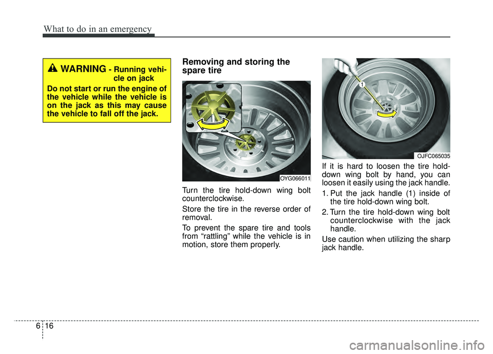
Removing and storing the
spare tire
Turn the tire hold-down wing bolt
counterclockwise.
Store the tire in the reverse order of
removal.
To prevent the spare tire and tools
from “rattling” while the vehicle is in
motion, store them properly. If it is hard to loosen the tire hold-
down wing bolt by hand, you can
loosen it easily using the jack handle.
1. Put the jack handle (1) inside of
the tire hold-down wing bolt.
2. Turn the tire hold-down wing bolt counterclockwise with the jack
handle.
Use caution when utilizing the sharp
jack handle.
WARNING- Running vehi- cle on jack
Do not start or run the engine of
the vehicle while the vehicle is
on the jack as this may cause
the vehicle to fall off the jack.
OYG066011
OJFC065035
Page 361 of 500
What to do in an emergency
18
6
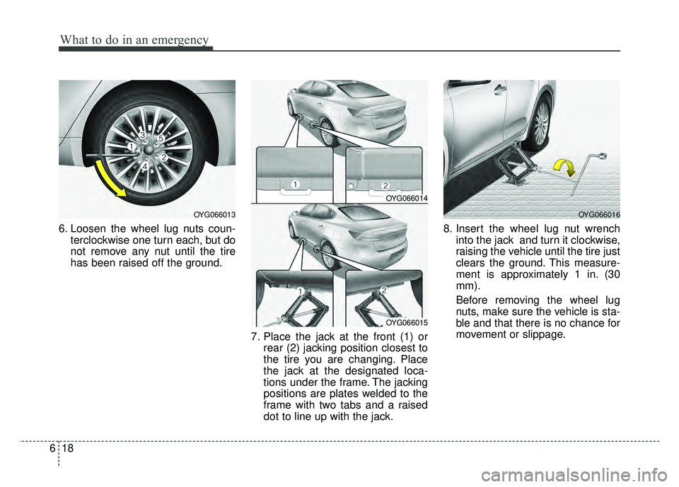
6. Loosen the wheel lug nuts coun-
terclockwise one turn each, but do
not remove any nut until the tire
has been raised off the ground.
7. Place the jack at the front (1) orrear (2) jacking position closest to
the tire you are changing. Place
the jack at the designated loca-
tions under the frame. The jacking
positions are plates welded to the
frame with two tabs and a raised
dot to line up with the jack. 8. Insert the wheel lug nut wrench
into the jack and turn it clockwise,
raising the vehicle until the tire just
clears the ground. This measure-
ment is approximately 1 in. (30
mm).
Before removing the wheel lug
nuts, make sure the vehicle is sta-
ble and that there is no chance for
movement or slippage.
OYG066016OYG066013
OYG066014
OYG066015
Page 362 of 500
619
What to do in an emergency
9. Loosen the wheel nuts andremove them with your fingers.
Slide the wheel off the studs and
lay it flat so it cannot roll away. To
put the wheel on the hub, pick up
the spare tire, line up the holes
with the studs and slide the wheel
onto them. If this is difficult, tip the
wheel slightly and get the top hole
in the wheel lined up with the top
stud. Jiggle the wheel back and
forth until the wheel can slide over
the other studs. Wheels may have sharp edges.
Handle them carefully to avoid possi-
ble severe injury. Before putting the
wheel into place, be sure that there
is nothing on the hub or wheel (such
as mud, tar, gravel, etc.) that pre-
vents the wheel from fitting solidly
against the hub.
10. To install the wheel, hold it on the
studs, put the wheel nuts on the
studs and tighten them finger
tight. Jiggle the tire to be sure it is
completely seated, then tighten
the nuts as much as possible
with your fingers again.
11. Insert the wrench into the jack and lower the vehicle to the
ground by turning the wheel nut
wrench counterclockwise.
WARNING- Installing a
wheel
Make sure the wheel makes
good contact with the hub when
installed. If the contact of the
mounting surface between the
wheel and hub is not good, the
wheel nuts could come loose
and cause the loss of a wheel.
Loss of a wheel may result in
loss of control of the vehicle.
Page 369 of 500
What to do in an emergency
26
6
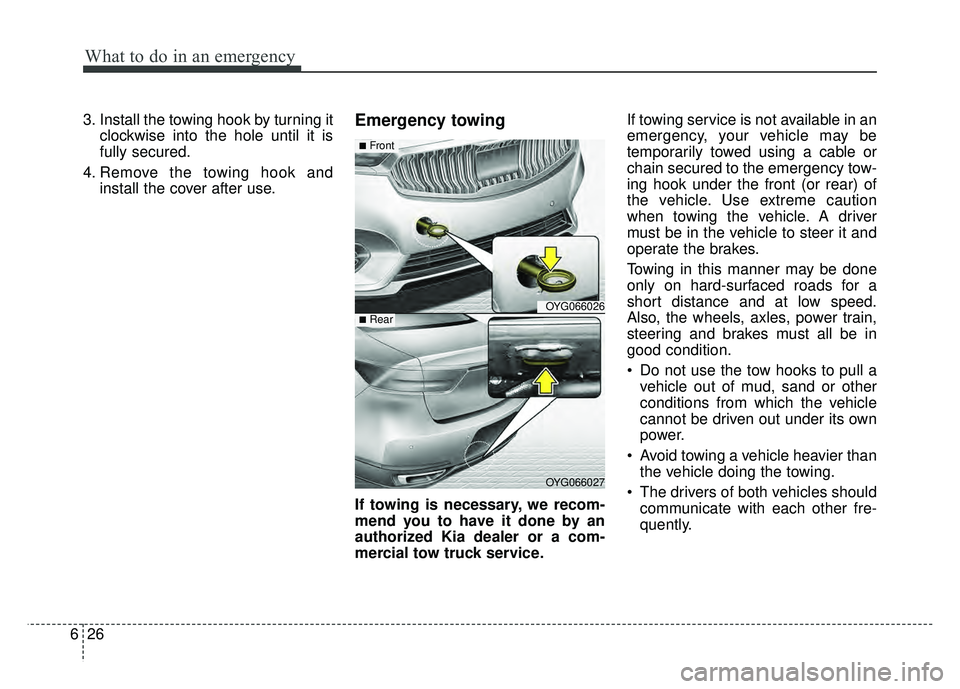
3. Install the towing hook by turning it
clockwise into the hole until it is
fully secured.
4. Remove the towing hook and install the cover after use.Emergency towing
If towing is necessary, we recom-
mend you to have it done by an
authorized Kia dealer or a com-
mercial tow truck service. If towing service is not available in an
emergency, your vehicle may be
temporarily towed using a cable or
chain secured to the emergency tow-
ing hook under the front (or rear) of
the vehicle. Use extreme caution
when towing the vehicle. A driver
must be in the vehicle to steer it and
operate the brakes.
Towing in this manner may be done
only on hard-surfaced roads for a
short distance and at low speed.
Also, the wheels, axles, power train,
steering and brakes must all be in
good condition.
Do not use the tow hooks to pull a
vehicle out of mud, sand or other
conditions from which the vehicle
cannot be driven out under its own
power.
Avoid towing a vehicle heavier than the vehicle doing the towing.
The drivers of both vehicles should communicate with each other fre-
quently.
OYG066026
OYG066027
■Front
■Rear
Page 397 of 500
Maintenance
26
7
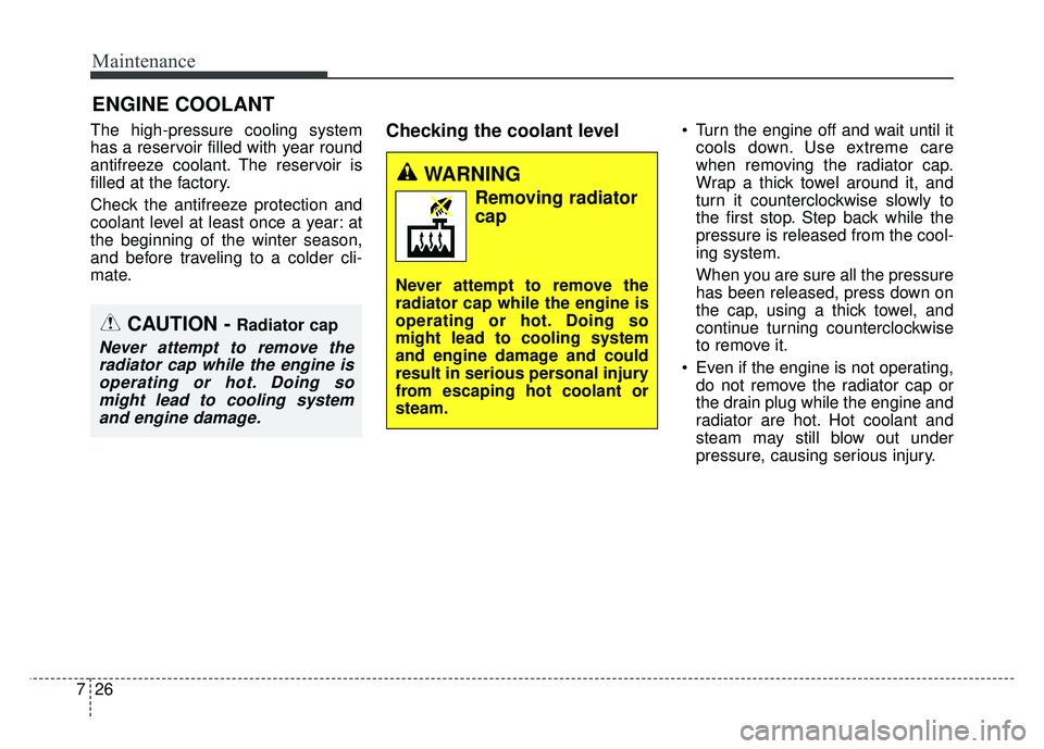
ENGINE COOLANT
The high-pressure cooling system
has a reservoir filled with year round
antifreeze coolant. The reservoir is
filled at the factory.
Check the antifreeze protection and
coolant level at least once a year: at
the beginning of the winter season,
and before traveling to a colder cli-
mate.Checking the coolant level Turn the engine off and wait until it
cools down. Use extreme care
when removing the radiator cap.
Wrap a thick towel around it, and
turn it counterclockwise slowly to
the first stop. Step back while the
pressure is released from the cool-
ing system.
When you are sure all the pressure
has been released, press down on
the cap, using a thick towel, and
continue turning counterclockwise
to remove it.
Even if the engine is not operating, do not remove the radiator cap or
the drain plug while the engine and
radiator are hot. Hot coolant and
steam may still blow out under
pressure, causing serious injury.
WARNING
Removing radiator
cap
Never attempt to remove the
radiator cap while the engine is
operating or hot. Doing so
might lead to cooling system
and engine damage and could
result in serious personal injury
from escaping hot coolant or
steam.
CAUTION - Radiator cap
Never attempt to remove theradiator cap while the engine isoperating or hot. Doing somight lead to cooling systemand engine damage.
Page 432 of 500

761
Maintenance
Fuse switch
Always set the fuse switch to the ON
position before using the vehicle.
If you move the switch to the OFF
position, some items such as audio
and digital clock must be reset and
transmitter (or smart key) may not
work properly. When the switch is
Off, the caution indicator will be dis-
played on the instrument cluster.
Always place the fuse switch in the
ON position while driving the vehicle.
If the switch is located in the “OFF”
position, a caution indicator will be
displayed in the cluster.
Engine compartment fuse
replacement
1. Turn the ignition switch and allother switches off.
2. Remove the fuse panel cover by pressing the tab and pulling the
cover up. When the blade type
fuse is disconnected, remove it by
using the clip designed for chang-
ing fuses located in the engine
compartment fuse box. Upon
removal, securely insert reserve
fuse of the same rating. 3. Check the removed fuse; replace it
if it is blown. To remove or insert
the fuse, use the fuse puller in the
engine compartment fuse panel.
4. Push in a new fuse of the same rating, and make sure it fits tightly
in the clips. If it fits loosely, consult
an authorized Kia dealer.
CAUTION
After checking the fuse panel inthe engine compartment,securely install the fuse panelcover through the audible click-ing sound.
If not, electrical failures mayoccur from water contact.
OYG076030
OYG076031