engine KIA CARNIVAL 2007 User Guide
[x] Cancel search | Manufacturer: KIA, Model Year: 2007, Model line: CARNIVAL, Model: KIA CARNIVAL 2007Pages: 1575, PDF Size: 44.86 MB
Page 18 of 1575
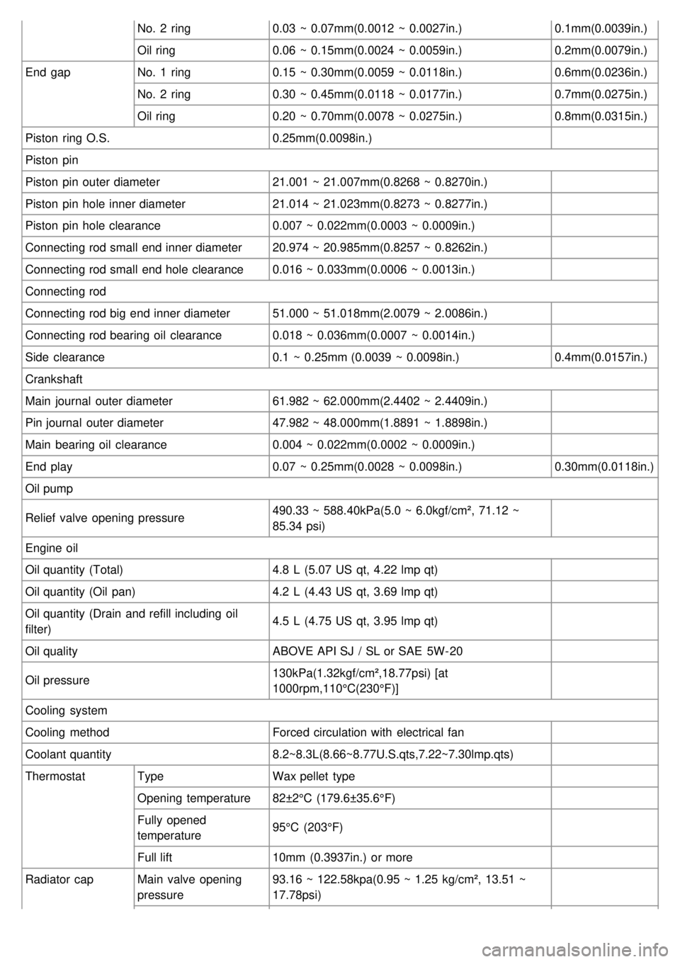
No. 2 ring0.03 ~ 0.07mm(0.0012 ~ 0.0027in.) 0.1mm(0.0039in.)
Oil ring 0.06 ~ 0.15mm(0.0024 ~ 0.0059in.) 0.2mm(0.0079in.)
End gap No. 1 ring 0.15 ~ 0.30mm(0.0059 ~ 0.0118in.) 0.6mm(0.0236in.)
No. 2 ring 0.30 ~ 0.45mm(0.0118 ~ 0.0177in.) 0.7mm(0.0275in.)
Oil ring 0.20 ~ 0.70mm(0.0078 ~ 0.0275in.) 0.8mm(0.0315in.)
Piston ring O.S. 0.25mm(0.0098in.)
Piston pin
Piston pin outer diameter 21.001 ~ 21.007mm(0.8268 ~ 0.8270in.)
Piston pin hole inner diameter 21.014 ~ 21.023mm(0.8273 ~ 0.8277in.)
Piston pin hole clearance 0.007 ~ 0.022mm(0.0003 ~ 0.0009in.)
Connecting rod small end inner diameter 20.974 ~ 20.985mm(0.8257 ~ 0.8262in.)
Connecting rod small end hole clearance 0.016 ~ 0.033mm(0.0006 ~ 0.0013in.)
Connecting rod
Connecting rod big end inner diameter 51.000 ~ 51.018mm(2.0079 ~ 2.0086in.)
Connecting rod bearing oil clearance 0.018 ~ 0.036mm(0.0007 ~ 0.0014in.)
Side clearance 0.1 ~ 0.25mm (0.0039 ~ 0.0098in.) 0.4mm(0.0157in.)
Crankshaft
Main journal outer diameter 61.982 ~ 62.000mm(2.4402 ~ 2.4409in.)
Pin journal outer diameter 47.982 ~ 48.000mm(1.8891 ~ 1.8898in.)
Main bearing oil clearance 0.004 ~ 0.022mm(0.0002 ~ 0.0009in.)
End play 0.07 ~ 0.25mm(0.0028 ~ 0.0098in.) 0.30mm(0.0118in.)
Oil pump
Relief valve opening pressure 490.33 ~ 588.40kPa(5.0 ~ 6.0kgf/cm², 71.12 ~
85.34 psi)
Engine oil
Oil quantity (Total) 4.8 L (5.07 US qt, 4.22 lmp qt)
Oil quantity (Oil pan) 4.2 L (4.43 US qt, 3.69 lmp qt)
Oil quantity (Drain and refill including oil
filter) 4.5 L (4.75 US qt, 3.95 lmp qt)
Oil quality ABOVE API SJ / SL or SAE 5W- 20
Oil pressure 130kPa(1.32kgf/cm²,18.77psi) [at
1000rpm,110°C(230°F)]
Cooling system
Cooling method Forced circulation with electrical fan
Coolant quantity 8.2~8.3L(8.66~8.77U.S.qts,7.22~7.30lmp.qts)
Thermostat Type Wax pellet type
Opening temperature 82±2°C (179.6±35.6°F)
Fully opened
temperature 95°C (203°F)
Full lift 10mm (0.3937in.) or more
Radiator cap Main valve opening
pressure 93.16 ~ 122.58kpa(0.95 ~ 1.25 kg/cm², 13.51 ~
17.78psi)
Page 19 of 1575
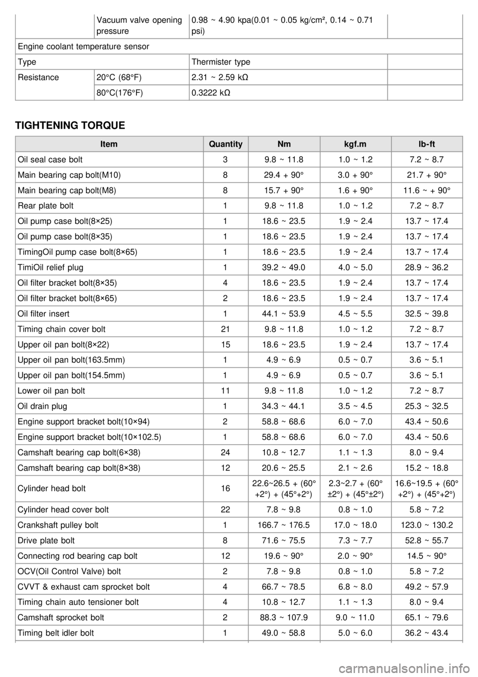
Vacuum valve opening
pressure0.98 ~ 4.90 kpa(0.01 ~ 0.05 kg/cm², 0.14 ~ 0.71
psi)
Engine coolant temperature sensor
Type Thermister type
Resistance 20°C (68°F) 2.31 ~ 2.59 kΩ
80°C(176°F) 0.3222 kΩ
TIGHTENING TORQUE
Item QuantityNmkgf.m lb- ft
Oil seal case bolt 39.8 ~ 11.8 1.0 ~ 1.27.2 ~ 8.7
Main bearing cap bolt(M10) 829.4 + 90° 3.0 + 90°21.7 + 90°
Main bearing cap bolt(M8) 815.7 + 90° 1.6 + 90°11.6 ~ + 90°
Rear plate bolt 19.8 ~ 11.8 1.0 ~ 1.27.2 ~ 8.7
Oil pump case bolt(8×25) 118.6 ~ 23.5 1.9 ~ 2.413.7 ~ 17.4
Oil pump case bolt(8×35) 118.6 ~ 23.5 1.9 ~ 2.413.7 ~ 17.4
TimingOil pump case bolt(8×65) 118.6 ~ 23.5 1.9 ~ 2.413.7 ~ 17.4
TimiOil relief plug 139.2 ~ 49.0 4.0 ~ 5.028.9 ~ 36.2
Oil filter bracket bolt(8×35) 418.6 ~ 23.5 1.9 ~ 2.413.7 ~ 17.4
Oil filter bracket bolt(8×65) 218.6 ~ 23.5 1.9 ~ 2.413.7 ~ 17.4
Oil filter insert 144.1 ~ 53.9 4.5 ~ 5.532.5 ~ 39.8
Timing chain cover bolt 219.8 ~ 11.8 1.0 ~ 1.27.2 ~ 8.7
Upper oil pan bolt(8×22) 1518.6 ~ 23.5 1.9 ~ 2.413.7 ~ 17.4
Upper oil pan bolt(163.5mm) 14.9 ~ 6.9 0.5 ~ 0.73.6 ~ 5.1
Upper oil pan bolt(154.5mm) 14.9 ~ 6.9 0.5 ~ 0.73.6 ~ 5.1
Lower oil pan bolt 119.8 ~ 11.8 1.0 ~ 1.27.2 ~ 8.7
Oil drain plug 134.3 ~ 44.1 3.5 ~ 4.525.3 ~ 32.5
Engine support bracket bolt(10×94) 258.8 ~ 68.6 6.0 ~ 7.043.4 ~ 50.6
Engine support bracket bolt(10×102.5) 158.8 ~ 68.6 6.0 ~ 7.043.4 ~ 50.6
Camshaft bearing cap bolt(6×38) 2410.8 ~ 12.7 1.1 ~ 1.38.0 ~ 9.4
Camshaft bearing cap bolt(8×38) 1220.6 ~ 25.5 2.1 ~ 2.615.2 ~ 18.8
Cylinder head bolt 1622.6~26.5 + (60°
+2°) + (45°+2°) 2.3~2.7 + (60°
±2°) + (45°±2°) 16.6~19.5 + (60°
+2°) + (45°+2°)
Cylinder head cover bolt 227.8 ~ 9.8 0.8 ~ 1.05.8 ~ 7.2
Crankshaft pulley bolt 1166.7 ~ 176.5 17.0 ~ 18.0123.0 ~ 130.2
Drive plate bolt 871.6 ~ 75.5 7.3 ~ 7.752.8 ~ 55.7
Connecting rod bearing cap bolt 1219.6 ~ 90° 2.0 ~ 90°14.5 ~ 90°
OCV(Oil Control Valve) bolt 27.8 ~ 9.8 0.8 ~ 1.05.8 ~ 7.2
CVVT & exhaust cam sprocket bolt 466.7 ~ 78.5 6.8 ~ 8.049.2 ~ 57.9
Timing chain auto tensioner bolt 410.8 ~ 12.7 1.1 ~ 1.38.0 ~ 9.4
Camshaft sprocket bolt 288.3 ~ 107.9 9.0 ~ 11.065.1 ~ 79.6
Timing belt idler bolt 149.0 ~ 58.8 5.0 ~ 6.036.2 ~ 43.4
Page 23 of 1575
2007 > 2.7L V6 GASOLINE >
REMOVAL
1.Remove the engine cover.
2. Remove the front right wheel and tire.
3. Remove the right side cover.
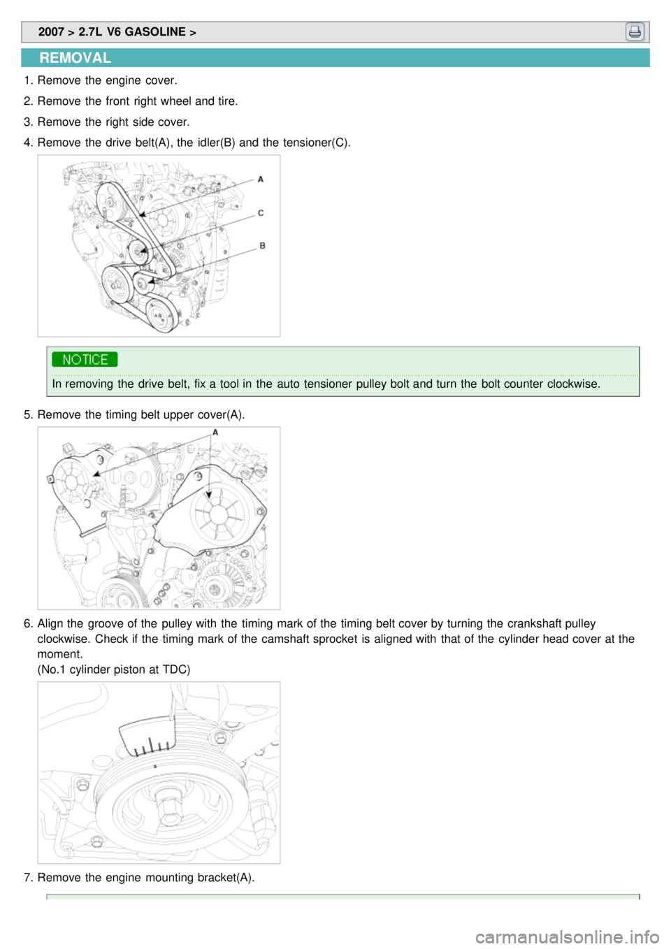
4. Remove the drive belt(A), the idler(B) and the tensioner(C).
In removing the drive belt, fix a tool in the auto tensioner pulley bolt and turn the bolt counter clockwise.
5. Remove the timing belt upper cover(A).
6.Align the groove of the pulley with the timing mark of the timing belt cover by turning the crankshaft pulley
clockwise. Check if the timing mark of the camshaft sprocket is aligned with that of the cylinder head cover at the
moment.
(No.1 cylinder piston at TDC)
7.Remove the engine mounting bracket(A).
Page 24 of 1575
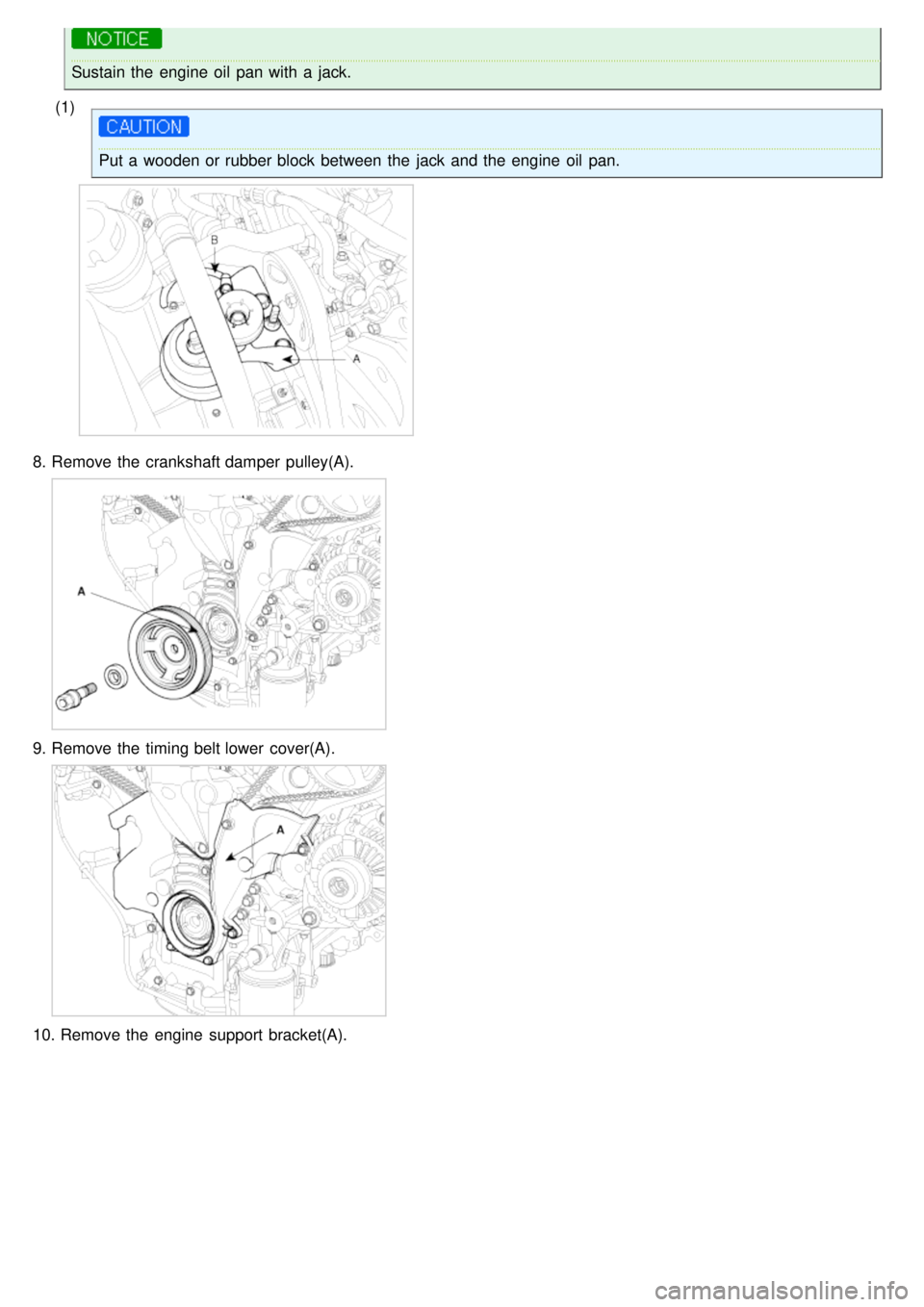
Sustain the engine oil pan with a jack.
(1)
Put a wooden or rubber block between the jack and the engine oil pan.
8. Remove the crankshaft damper pulley(A).
9.Remove the timing belt lower cover(A).
10. Remove the engine support bracket(A).
Page 25 of 1575
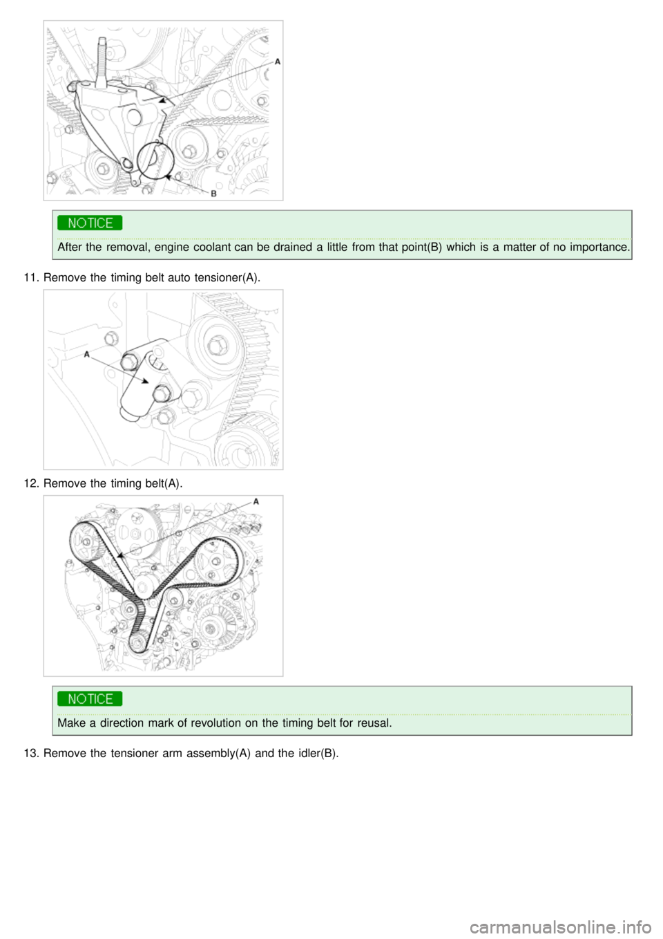
After the removal, engine coolant can be drained a little from that point(B) which is a matter of no importance.
11. Remove the timing belt auto tensioner(A).
12.Remove the timing belt(A).
Make a direction mark of revolution on the timing belt for reusal.
13. Remove the tensioner arm assembly(A) and the idler(B).
Page 26 of 1575
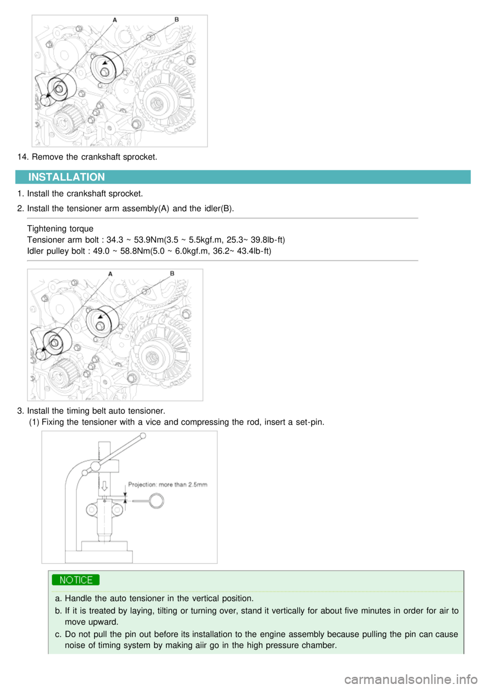
14.Remove the crankshaft sprocket.
INSTALLATION
1.Install the crankshaft sprocket.
2. Install the tensioner arm assembly(A) and the idler(B).
Tightening torque
Tensioner arm bolt : 34.3 ~ 53.9Nm(3.5 ~ 5.5kgf.m, 25.3~ 39.8lb- ft)
Idler pulley bolt : 49.0 ~ 58.8Nm(5.0 ~ 6.0kgf.m, 36.2~ 43.4lb- ft)
3.Install the timing belt auto tensioner.
(1) Fixing the tensioner with a vice and compressing the rod, insert a set- pin.
a.Handle the auto tensioner in the vertical position.
b. If it is treated by laying, tilting or turning over, stand it vertically for about five minutes in order for air to
move upward.
c. Do not pull the pin out before its installation to the engine assembly because pulling the pin can cause
noise of timing system by making aiir go in the high pressure chamber.
Page 27 of 1575
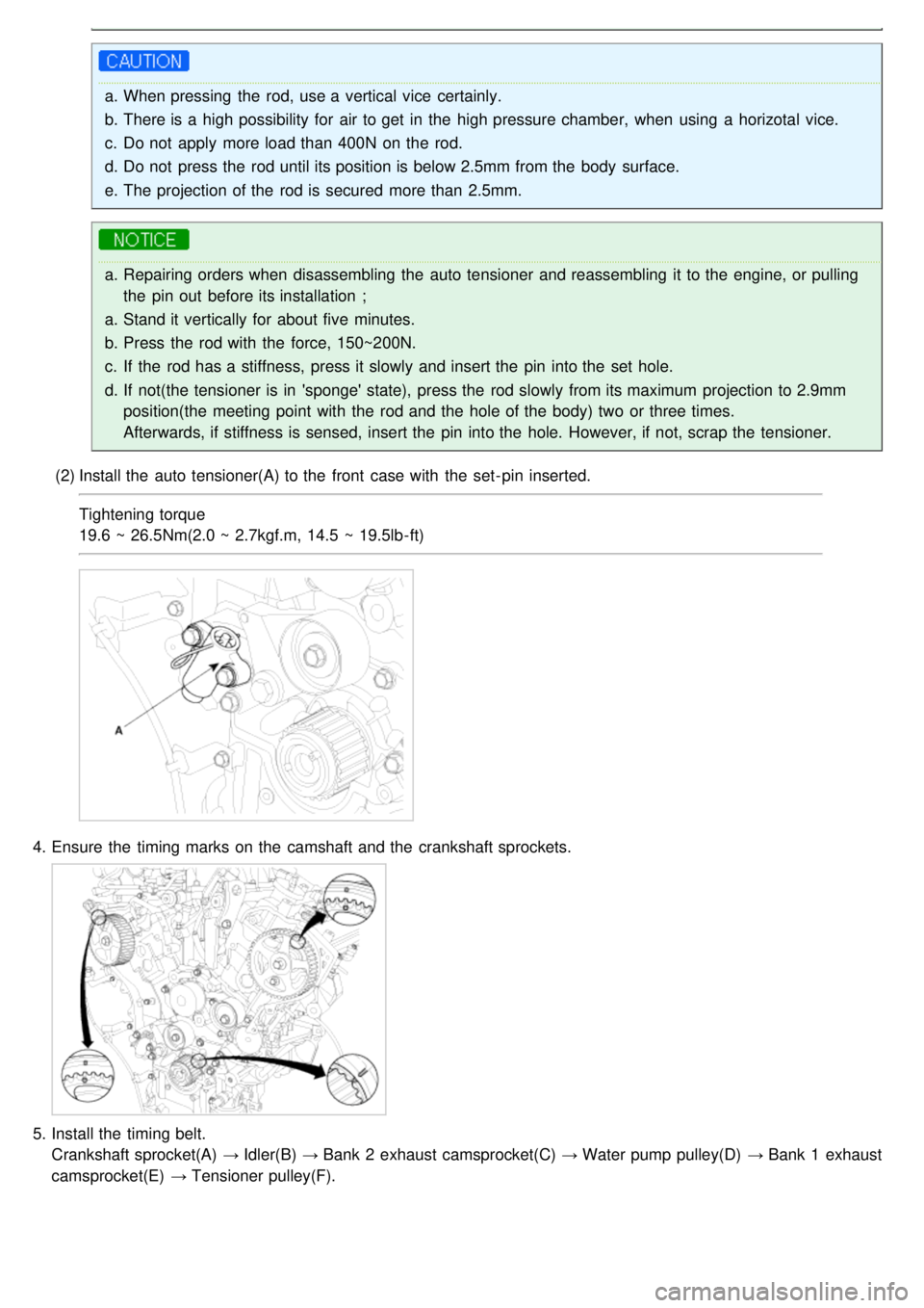
a.When pressing the rod, use a vertical vice certainly.
b. There is a high possibility for air to get in the high pressure chamber, when using a horizotal vice.
c. Do not apply more load than 400N on the rod.
d. Do not press the rod until its position is below 2.5mm from the body surface.
e. The projection of the rod is secured more than 2.5mm.
a.Repairing orders when disassembling the auto tensioner and reassembling it to the engine, or pulling
the pin out before its installation ;
a. Stand it vertically for about five minutes.
b. Press the rod with the force, 150~200N.
c. If the rod has a stiffness, press it slowly and insert the pin into the set hole.
d. If not(the tensioner is in 'sponge' state), press the rod slowly from its maximum projection to 2.9mm
position(the meeting point with the rod and the hole of the body) two or three times.
Afterwards, if stiffness is sensed, insert the pin into the hole. However, if not, scrap the tensioner.
(2) Install the auto tensioner(A) to the front case with the set- pin inserted.
Tightening torque
19.6 ~ 26.5Nm(2.0 ~ 2.7kgf.m, 14.5 ~ 19.5lb- ft)
4.Ensure the timing marks on the camshaft and the crankshaft sprockets.
5.Install the timing belt.
Crankshaft sprocket(A) → Idler(B) → Bank 2 exhaust camsprocket(C) → Water pump pulley(D) → Bank 1 exhaust
camsprocket(E) → Tensioner pulley(F).
Page 28 of 1575
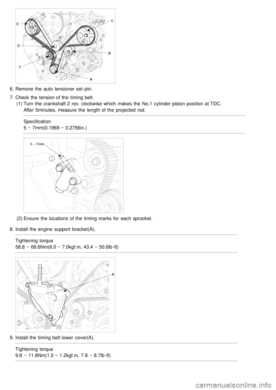
6.Remove the auto tensioner set- pin.
7. Check the tension of the timing belt.
(1) Turn the crankshaft 2 rev. clockwise which makes the No.1 cylinder piston position at TDC.
After 5minutes, measure the length of the projected rod.
Specification
5 ~ 7mm(0.1969 ~ 0.2756in.)
(2)Ensure the locations of the timing marks for each sprocket.
8. Install the engine support bracket(A).
Tightening torque
58.8 ~ 68.6Nm(6.0 ~ 7.0kgf.m, 43.4 ~ 50.6lb- ft)
9.Install the timing belt lower cover(A).
Tightening torque
9.8 ~ 11.8Nm(1.0 ~ 1.2kgf.m, 7.8 ~ 8.7lb - ft)
Page 29 of 1575
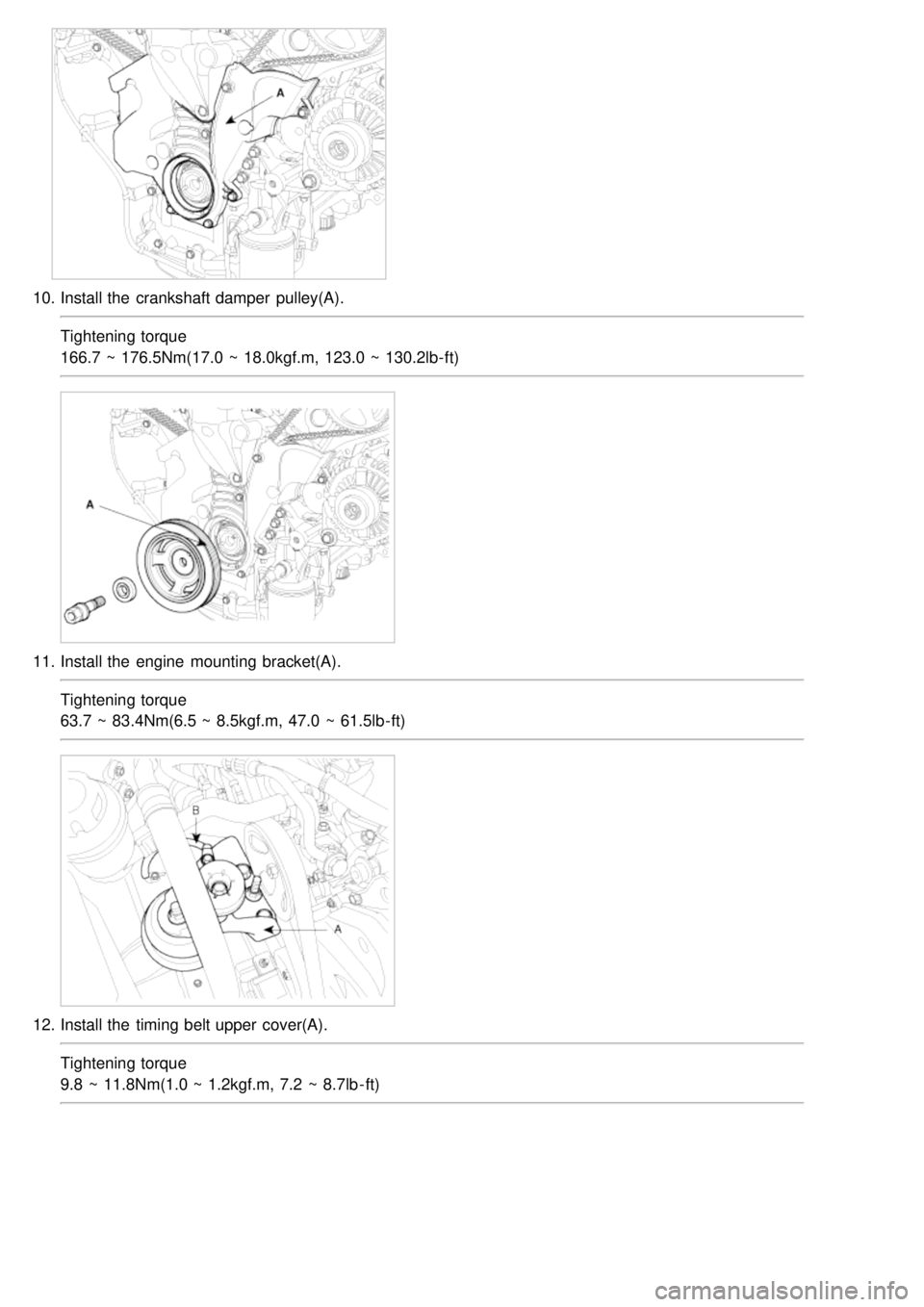
10.Install the crankshaft damper pulley(A).
Tightening torque
166.7 ~ 176.5Nm(17.0 ~ 18.0kgf.m, 123.0 ~ 130.2lb- ft)
11.Install the engine mounting bracket(A).
Tightening torque
63.7 ~ 83.4Nm(6.5 ~ 8.5kgf.m, 47.0 ~ 61.5lb- ft)
12.Install the timing belt upper cover(A).
Tightening torque
9.8 ~ 11.8Nm(1.0 ~ 1.2kgf.m, 7.2 ~ 8.7lb - ft)
Page 30 of 1575
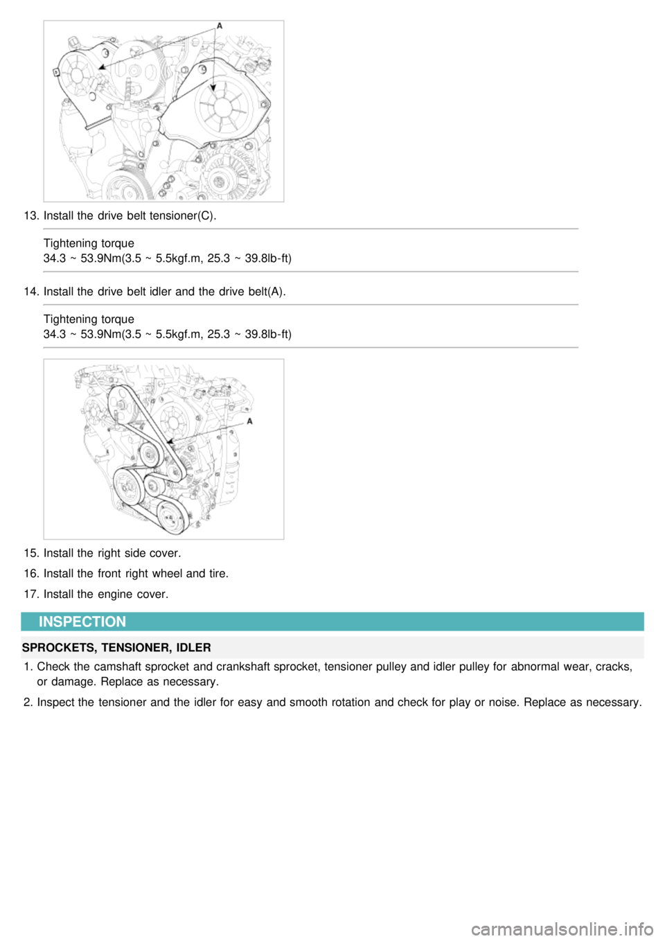
13.Install the drive belt tensioner(C).
Tightening torque
34.3 ~ 53.9Nm(3.5 ~ 5.5kgf.m, 25.3 ~ 39.8lb- ft)
14. Install the drive belt idler and the drive belt(A).
Tightening torque
34.3 ~ 53.9Nm(3.5 ~ 5.5kgf.m, 25.3 ~ 39.8lb- ft)
15.Install the right side cover.
16. Install the front right wheel and tire.
17. Install the engine cover.
INSPECTION
SPROCKETS, TENSIONER, IDLER
1. Check the camshaft sprocket and crankshaft sprocket, tensioner pulley and idler pulley for abnormal wear, cracks,
or damage. Replace as necessary.
2. Inspect the tensioner and the idler for easy and smooth rotation and check for play or noise. Replace as necessary.