engine KIA CARNIVAL 2007 Owner's Manual
[x] Cancel search | Manufacturer: KIA, Model Year: 2007, Model line: CARNIVAL, Model: KIA CARNIVAL 2007Pages: 1575, PDF Size: 44.86 MB
Page 31 of 1575
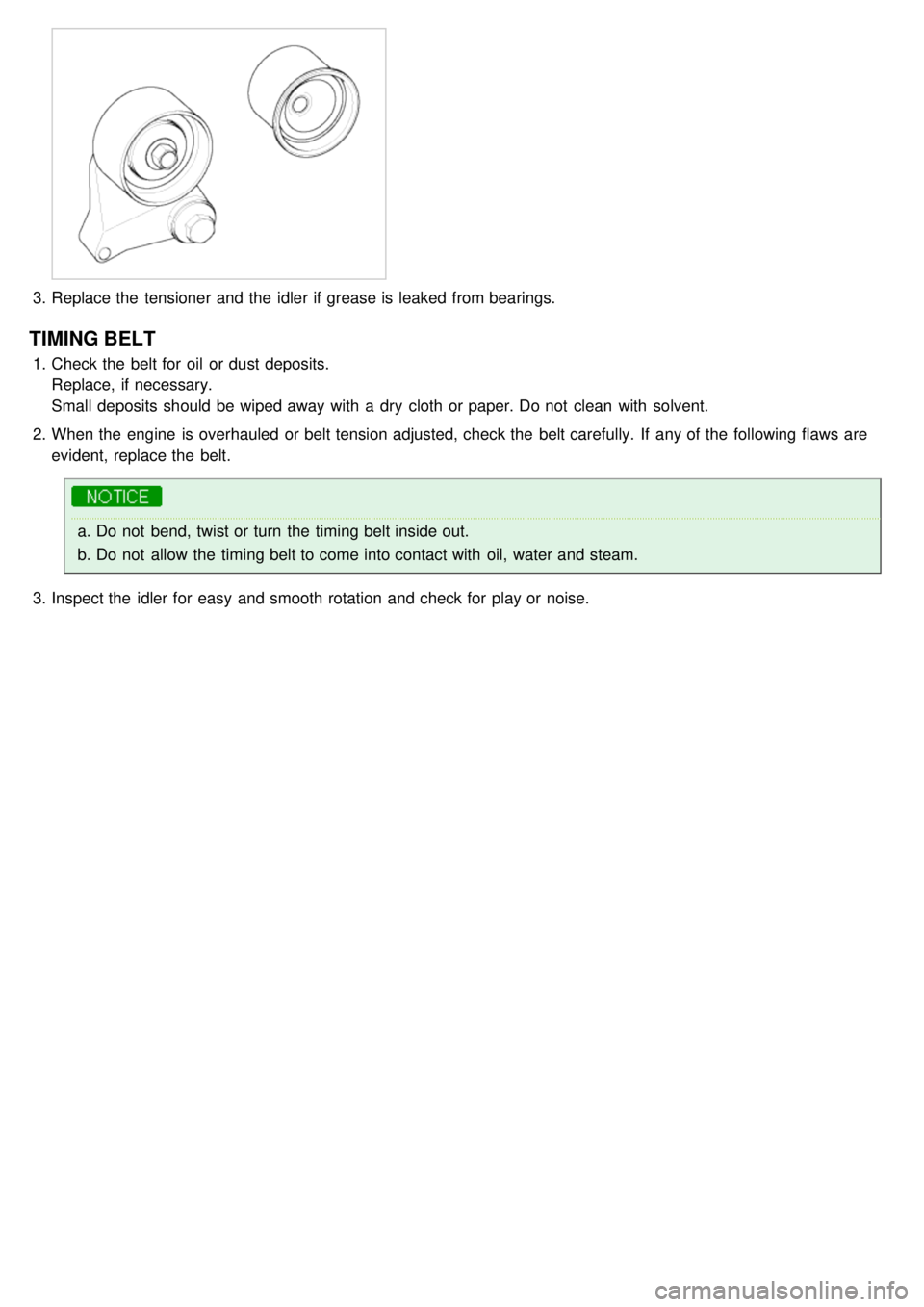
3.Replace the tensioner and the idler if grease is leaked from bearings.
TIMING BELT
1.Check the belt for oil or dust deposits.
Replace, if necessary.
Small deposits should be wiped away with a dry cloth or paper. Do not clean with solvent.
2. When the engine is overhauled or belt tension adjusted, check the belt carefully. If any of the following flaws are
evident, replace the belt.
a.Do not bend, twist or turn the timing belt inside out.
b. Do not allow the timing belt to come into contact with oil, water and steam.
3. Inspect the idler for easy and smooth rotation and check for play or noise.
Page 35 of 1575
2007 > 2.7L V6 GASOLINE >
REMOVAL
a.Use fender covers to avoid damaging painted surfaces.
b. To avoid damaging the cylinder head, wait until the engine coolant temperature drops below normal
temperature before removing it.
c. When handling a metal gasket, take care not to fold the gasket or damage the contact surface of the gasket.
d. To avoid damage, unplug the wiring connectors carefully while holding the connector portion.
a.Mark all wiring and hoses to avoid misconnection.
b. Turn the crankshaft pulley so that the No. 1 piston is at top dead center.
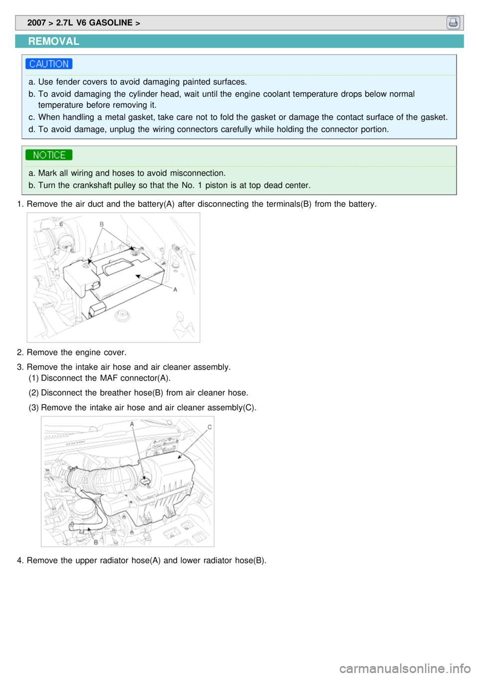
1. Remove the air duct and the battery(A) after disconnecting the terminals(B) from the battery.
2.Remove the engine cover.
3. Remove the intake air hose and air cleaner assembly.
(1) Disconnect the MAF connector(A).
(2) Disconnect the breather hose(B) from air cleaner hose.
(3) Remove the intake air hose and air cleaner assembly(C).
4.Remove the upper radiator hose(A) and lower radiator hose(B).
Page 36 of 1575
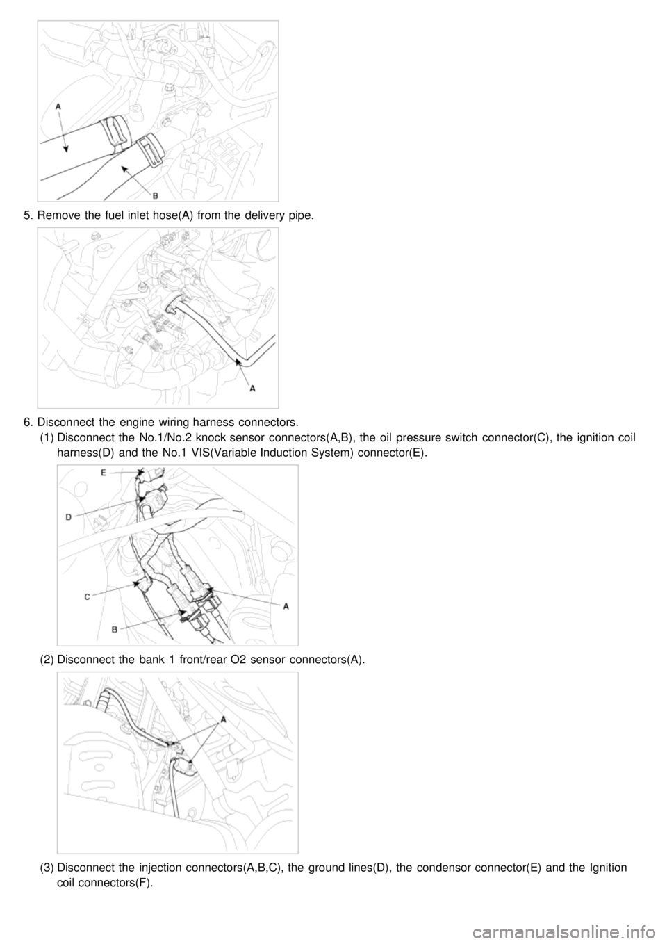
5.Remove the fuel inlet hose(A) from the delivery pipe.
6.Disconnect the engine wiring harness connectors.
(1) Disconnect the No.1/No.2 knock sensor connectors(A,B), the oil pressure switch connector(C), the ignition coil
harness(D) and the No.1 VIS(Variable Induction System) connector(E).
(2)Disconnect the bank 1 front/rear O2 sensor connectors(A).
(3)Disconnect the injection connectors(A,B,C), the ground lines(D), the condensor connector(E) and the Ignition
coil connectors(F).
Page 38 of 1575

(7)Disconnect the bank 2 CMP sensor connector(A) and the ECT(Engine Coolant Temperature) sensor
connector(B).
(8)Disconnect the bank 2 front/rear O2 sensor connectors(A,B) and the CKP sensor connector(C).
(9)Disconnect the bank 1 CMP sensor connector(A).
7.Remove the PCV(Pulge Control Valve) hose(A).
Page 43 of 1575

Ensure the LH/RH classification of the cylinder head gasket when installing.
2. Tighten the cylinder head bolts with the plain washers in several steps as following order.
a.In assembling washers, the marked surface should face upward.
b. In installing the cylinder head bolts, apply engine oil on the thread of the bolts and the surface of the
washers.
Tightening torque
22.6~26.5Nm(2.3~2.7kgf.m, 16.6~19.5lb - ft) + (60° + 2°) + (45° + 2°)
Using the SST(09221- 4A000), tighten the bolts which need to be tightened with the angular tightening method.
3. Install the CVVT assembly and camshaft chain sprocket with the dowel pin in the CVVT installed to the intake
camshaft. Ensure that the pin will not be installed in the hole for oil feeding.
Page 46 of 1575

7.Using the SST(09214- 21000), install the camshaft oil seal.
a.Befor installing, apply engine oil.
b. The camshaft cap surface should adhere to the cylinder head assembly.
c. Do not press an eccentric load.
8. Install the CKP sensor connector bracket(A).
9.Install the bank 1 timing belt rear cover(A).
10. Install the bank 2 timing belt rear cover(A).
Page 48 of 1575

a.Do not start engine for thirty minites after assembling the cylinder head cover.
b. Do not reuse the cylinder head cover gasket.
14. Install the water temp. control assembly.
15. Install the intake manifold assembly.
16. Install the exhaust mainfold assembly.
17. Install the power steering pump.(Refer to 'ST' group).
18. Install the drive belt(A).
19.Install the heater hose.
20. Connect the brake vaccume hose(A).
21.Install the PCV(Pulge Control Valve) hose(A).
22.Connect the engine wiring harness connectors.
(1) Connect the bank 1 CMP sensor connector(A).
Page 52 of 1575

(2)Connect the breather hose(B) from air cleaner hose.
(3) Connect the MAF connector(A).
26. Install the engine cover.
27. Refill engine coolant.
DISASSEMBLY
Identify MLA(Mechanical Lash Adjuster), valves and valve springs as they are removed so that each item can be
reinstalled in its original position.
1. Remove MLA(Mechanical Lash Adjuster)s(A).
2.Remove valves.
(1) Using SST(09222- 3K000, 09222 - 3C300), compress the valve spring and remove retainer lock.
(2)Remove the spring retainer.
(3) Remove the valve spring.
(4) Remove the valve.
Page 59 of 1575
REASSEMBLY
a.Thoroughly clean all parts to be assembled.
b. Before installing the parts, apply fresh engine oil to all sliding and rotating surfaces.
c. Replace oil seals with new ones.
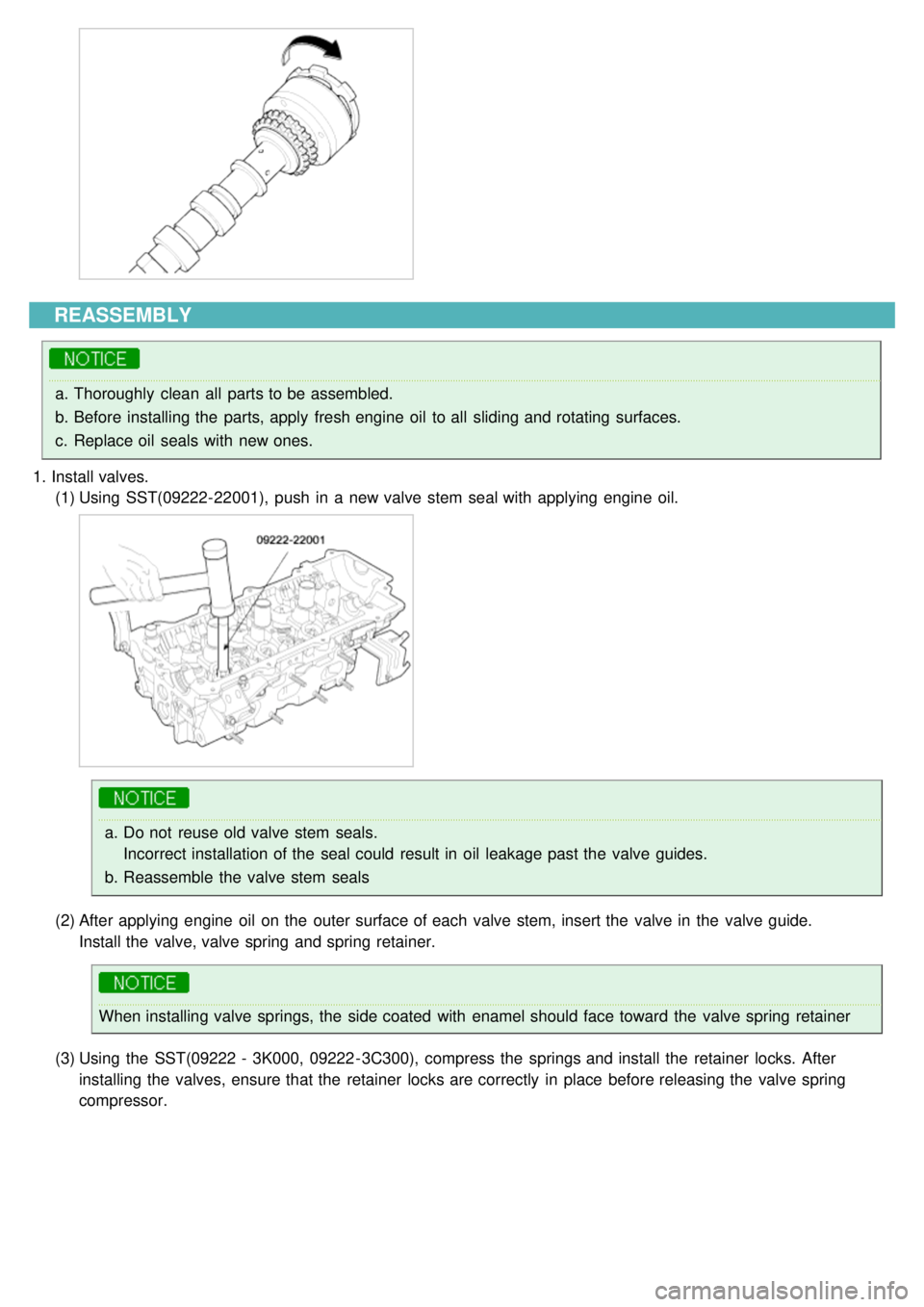
1. Install valves.
(1) Using SST(09222- 22001), push in a new valve stem seal with applying engine oil.
a.Do not reuse old valve stem seals.
Incorrect installation of the seal could result in oil leakage past the valve guides.
b. Reassemble the valve stem seals
(2) After applying engine oil on the outer surface of each valve stem, insert the valve in the valve guide.
Install the valve, valve spring and spring retainer.
When installing valve springs, the side coated with enamel should face toward the valve spring retainer
(3) Using the SST(09222 - 3K000, 09222 - 3C300), compress the springs and install the retainer locks. After
installing the valves, ensure that the retainer locks are correctly in place before releasing the valve spring
compressor.
Page 60 of 1575
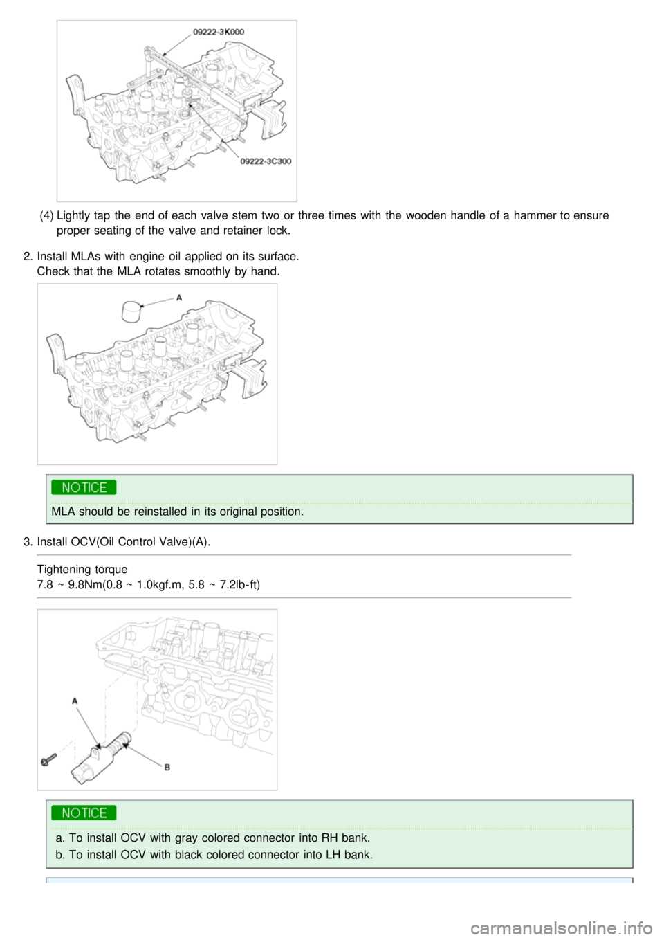
(4)Lightly tap the end of each valve stem two or three times with the wooden handle of a hammer to ensure
proper seating of the valve and retainer lock.
2. Install MLAs with engine oil applied on its surface.
Check that the MLA rotates smoothly by hand.
MLA should be reinstalled in its original position.
3. Install OCV(Oil Control Valve)(A).
Tightening torque
7.8 ~ 9.8Nm(0.8 ~ 1.0kgf.m, 5.8 ~ 7.2lb - ft)
a.To install OCV with gray colored connector into RH bank.
b. To install OCV with black colored connector into LH bank.