tailgate trim KIA CARNIVAL 2007 User Guide
[x] Cancel search | Manufacturer: KIA, Model Year: 2007, Model line: CARNIVAL, Model: KIA CARNIVAL 2007Pages: 1575, PDF Size: 44.86 MB
Page 1204 of 1575
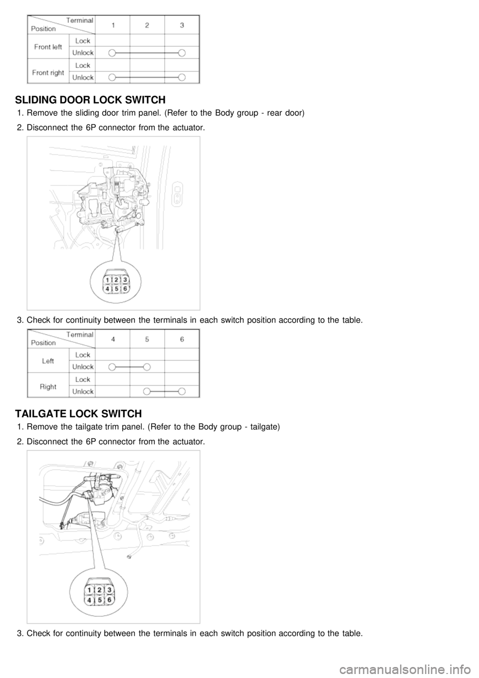
SLIDING DOOR LOCK SWITCH
1.Remove the sliding door trim panel. (Refer to the Body group - rear door)
2. Disconnect the 6P connector from the actuator.
3.Check for continuity between the terminals in each switch position according to the table.
TAILGATE LOCK SWITCH
1.Remove the tailgate trim panel. (Refer to the Body group - tailgate)
2. Disconnect the 6P connector from the actuator.
3.Check for continuity between the terminals in each switch position according to the table.
Page 1316 of 1575

TAILGATE LOCK ACTUATOR
1.Remove the tailgate trim panel. (Refer to the Body group - tailgate)
2. Disconnect the 6P connector from the actuator.
3.Check actuator operation by connecting power and ground according to the table. To prevent damage to the
actuator, apply battery voltage only momentarily.
FRONT DOOR LOCK SWITCH
1.Remove the front door trim panel. (Refer to the Body group - Front door)
2. Disconnect the 6P connector from the actuator.
3.Check for continuity between the terminals in each switch position according to the table.
SLIDING DOOR LOCK SWITCH
1.Remove the rear door trim panel. (Refer to the Body group - Rear door)
2. Disconnect the 6P connector from the actuator.
Page 1317 of 1575

3.Check for continuity between the terminals in each switch position according to the table.
TAILGATE LOCK SWITCH
1.Remove the tailgate trim panel. (Refer to the Body group - tailgate)
2. Disconnect the 6P connector from the actuator.
3.Check for continuity between the terminals in each switch position according to the table.
FRONT DOOR KIEY SWITCH
1.Remove the front door trim panel. (Refer to the Body group - Front door)
2. Disconnect the 3P connector from the actuator.
Page 1318 of 1575

3.Check for continuity between the terminals in each switch position according to the table.
TAILGATE KEY SWITCH
1.Remove the tailgate trim panel. (Refer to the Body group - tailgate)
2. Disconnect the 3P connector from the actuator.
3.Check for continuity between the terminals in each switch position according to the table.
Page 1326 of 1575
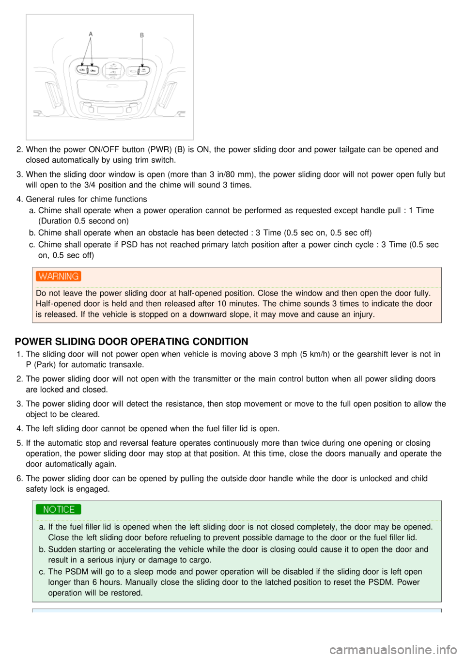
2.When the power ON/OFF button (PWR) (B) is ON, the power sliding door and power tailgate can be opened and
closed automatically by using trim switch.
3. When the sliding door window is open (more than 3 in/80 mm), the power sliding door will not power open fully but
will open to the 3/4 position and the chime will sound 3 times.
4. General rules for chime functions
a. Chime shall operate when a power operation cannot be performed as requested except handle pull : 1 Time
(Duration 0.5 second on)
b. Chime shall operate when an obstacle has been detected : 3 Time (0.5 sec on, 0.5 sec off)
c. Chime shall operate if PSD has not reached primary latch position after a power cinch cycle : 3 Time (0.5 sec
on, 0.5 sec off)
Do not leave the power sliding door at half- opened position. Close the window and then open the door fully.
Half - opened door is held and then released after 10 minutes. The chime sounds 3 times to indicate the door
is released. If the vehicle is stopped on a downward slope, it may move and cause an injury.
POWER SLIDING DOOR OPERATING CONDITION
1.The sliding door will not power open when vehicle is moving above 3 mph (5 km/h) or the gearshift lever is not in
P (Park) for automatic transaxle.
2. The power sliding door will not open with the transmitter or the main control button when all power sliding doors
are locked and closed.
3. The power sliding door will detect the resistance, then stop movement or move to the full open position to allow the
object to be cleared.
4. The left sliding door cannot be opened when the fuel filler lid is open.
5. If the automatic stop and reversal feature operates continuously more than twice during one opening or closing
operation, the power sliding door may stop at that position. At this time, close the doors manually and operate the
door automatically again.
6. The power sliding door can be opened by pulling the outside door handle while the door is unlocked and child
safety lock is engaged.
a.If the fuel filler lid is opened when the left sliding door is not closed completely, the door may be opened.
Close the left sliding door before refueling to prevent possible damage to the door or the fuel filler lid.
b. Sudden starting or accelerating the vehicle while the door is closing could cause it to open the door and
result in a serious injury or damage to cargo.
c. The PSDM will go to a sleep mode and power operation will be disabled if the sliding door is left open
longer than 6 hours. Manually close the sliding door to the latched position to reset the PSDM. Power
operation will be restored.
Page 1380 of 1575

4.Select the sensor output. And then check the clutch feedback sensor output while operating power tailgate in
power mode.
※ Above voltage and numerical value may be different from the real value.
5. Change the drive unit, if there is no change during operation.
REPLACEMENT
1.Disconnect the negative ( - ) battery terminal.
2. Remove the third, fourth seat (Refer to the Body group - seat)
3. Remove the D pillar and luggage side trim (Refer to the Body group - Interior trim).
4. Use a small screw driver to loosen clip (A). But do not remove power tailgate push rod (B).
5.Remove the power tail gate motor mounting bolts (3EA) and connectors (4EA). And then remove the power tail
gate drive unit(A).
TORQUE : 22- 27N.m(2.2- 2.7Kg.m)
Page 1382 of 1575
2007 > 2.7L V6 GASOLINE >
REPLACEMENT
1.Disconnect the negative ( - ) battery terminal.
2. Remove the third, fourth seat (Refer to the Body group - seat)
3. Remove the D pillar and luggage side trim (Refer to the Body group - Interior trim).
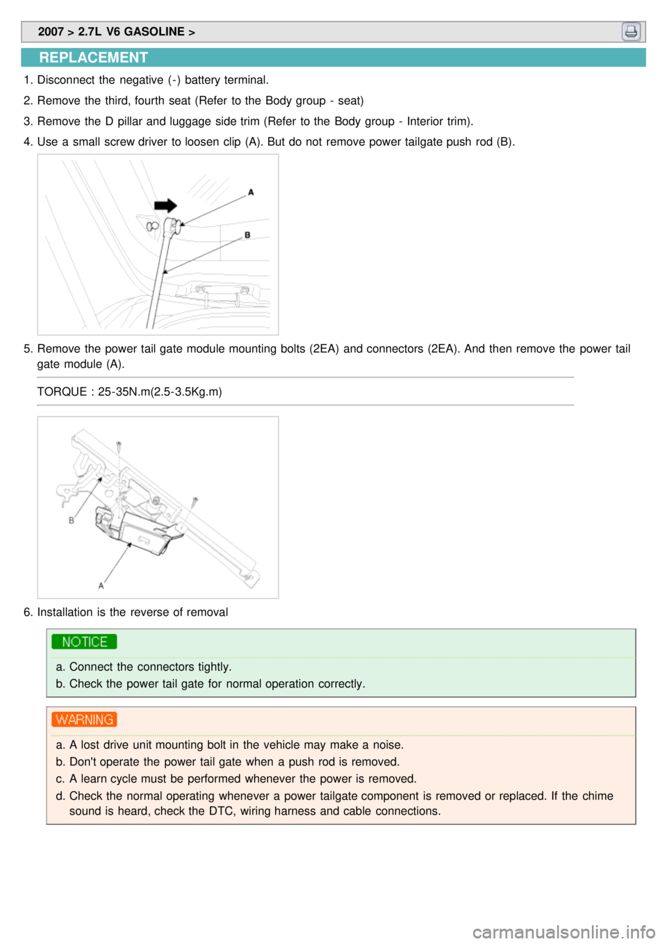
4. Use a small screw driver to loosen clip (A). But do not remove power tailgate push rod (B).
5.Remove the power tail gate module mounting bolts (2EA) and connectors (2EA). And then remove the power tail
gate module (A).
TORQUE : 25- 35N.m(2.5- 3.5Kg.m)
6.Installation is the reverse of removal
a.Connect the connectors tightly.
b. Check the power tail gate for normal operation correctly.
a.A lost drive unit mounting bolt in the vehicle may make a noise.
b. Don't operate the power tail gate when a push rod is removed.
c. A learn cycle must be performed whenever the power is removed.
d. Check the normal operating whenever a power tailgate component is removed or replaced. If the chime
sound is heard, check the DTC, wiring harness and cable connections.
Page 1384 of 1575

2007 > 2.7L V6 GASOLINE >
INSPECTION
1.Check the power tail gate control module input/output value by using the diagnostic tool. If the operation of tailgate
control module is abnormal, replace anti pinch strip control module.
2. When checking the anti pinch strip operation, select a vehicle type and "POWER SLIDING/TAILGATE" menu.
3.Select "POWER TAILGATE".
4.Select the sensor output. And then check the anti pinch strip sensor output while operating power tailgate in power
mode.
※ Above voltage and numerical value may be different from the real value.
5. Change the anti pinch strip sensor, if there is no change from OFF to ON during operation.
REPLACEMENT
1.Disconnect the negative ( - ) battery terminal.
2. Remove the tail gate trim (Refer to the Body group - tail gate).
3. Remove the anti- pinch strip sensor connector (A).
Page 1387 of 1575

2007 > 2.7L V6 GASOLINE >
INPECTION
1.Check the power tail gate control module input/output value by using the diagnostic tool. If the operation of tailgate
control module is abnormal, replace power latch.
2. To check the power latch operation, select a vehicle type and "POWER SLIDING/TAILGATE" menu.
3.Select "POWER TAILGATE".
4.Select the sensor output. And then check the cinch feedback and unlatch feedback output while operating power
tailgate in power mode.
※ Above voltage and numerical value may be different from the real value.
5. Change the anti pinch strip sensor, if there is no change during operation.
REPLACEMENT
1.Disconnect the negative ( - ) battery terminal.
2. Remove the tail gate trim (Refer to the Body group - tail gate).
3. Remove the tail gate handle rod, actuator rod and key rod.
4. Remove the unlatch actuator assembly (A) after removing the connector and nuts (3EA).