light KIA CARNIVAL 2007 Owner's Guide
[x] Cancel search | Manufacturer: KIA, Model Year: 2007, Model line: CARNIVAL, Model: KIA CARNIVAL 2007Pages: 1575, PDF Size: 44.86 MB
Page 627 of 1575

7.Mount the pump in a vise and remove the pulley (A) nut and the spring washer.
8.After removing the snap ring (A) of the shaft with snap ring pliers, remove the dust spacer.
9.Tap the rotor side of the shaft slightly with a plastic hammer (A) to remove the shaft (B).
10. Remove the oil seal from the oil pump body.
When assembling, use a new oil seal.
11. Remove the connector from the oil pump body, and take out the flow control valve (A) and the flow control spring
(B).
Page 656 of 1575

In order to use the leak detector properly, read the manual supplied by the manufacturer.
If a gas leak is detected, proceed as follows: 1. Check the torque on the connection fittings and, if too loose, tighten to the proper torque. Check for gas leakage
with a leak detector (A).
2. If leakage continues even after the fitting has been tightened, discharge the refrigerant from the system, disconnect
the fittings, and check their seating faces for damage. Always replace, even if the damage is slight.
3. Check the compressor oil and add oil if required.
4. Charge the system and recheck for gas leaks. If no leaks are found, evacuate and charge the system again.
Page 688 of 1575

2007 > 2.7L V6 GASOLINE >
DESCRIPTION
1.The photo sensor (A) is located at the center of defrost nozzle.
2. The photo sensor contains a photovoltaic (sensitive to sunlight) diode. The solar radiation received by its light
receiving portion, generates an electromotive force in proportion to the amount of radiation received which is
transferred to the automatic temperature control module so that the solar radiation compensation will be performed.
Page 689 of 1575

2007 > 2.7L V6 GASOLINE >
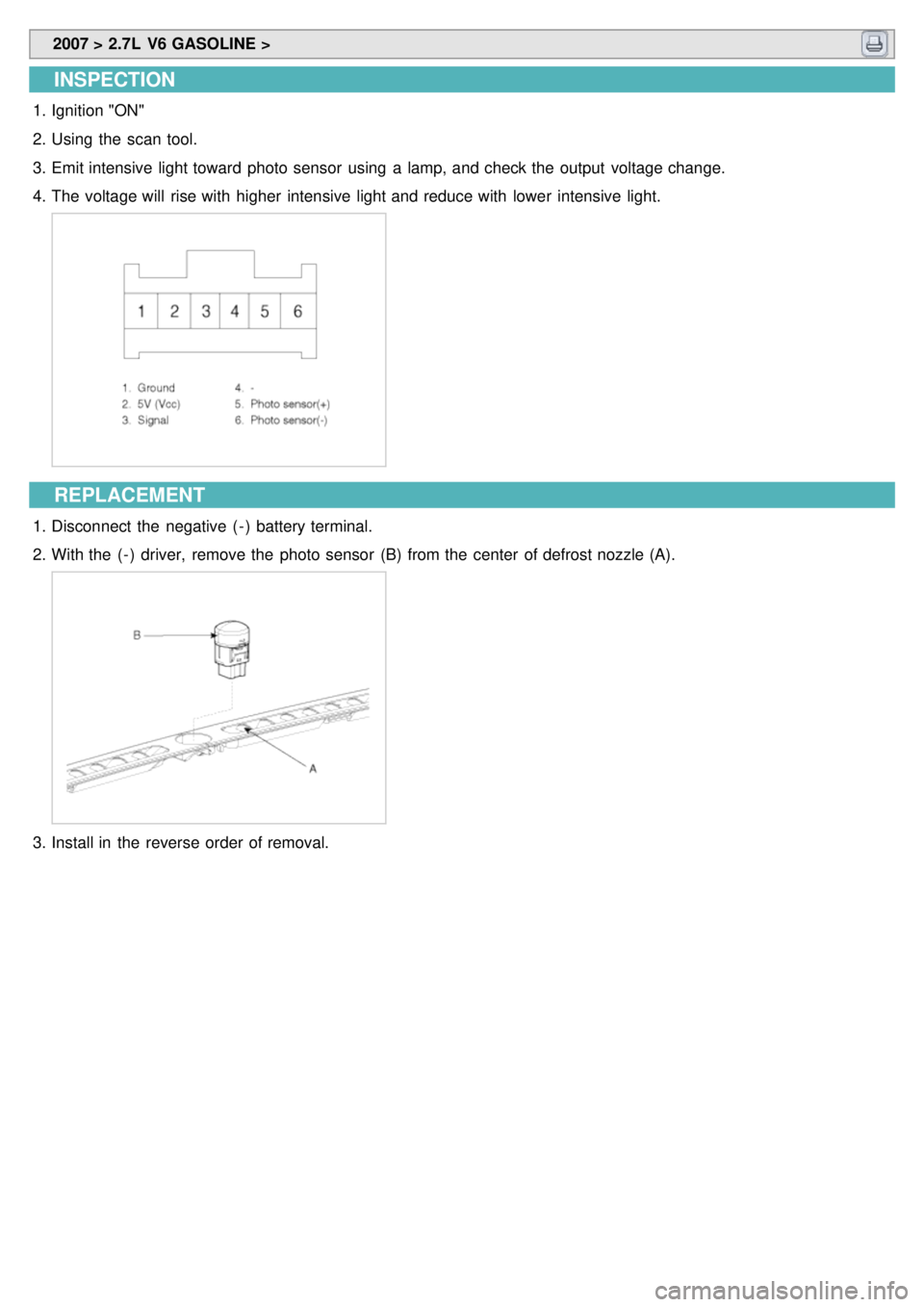
INSPECTION
1.Ignition "ON"
2. Using the scan tool.
3. Emit intensive light toward photo sensor using a lamp, and check the output voltage change.
4. The voltage will rise with higher intensive light and reduce with lower intensive light.
REPLACEMENT
1.Disconnect the negative ( - ) battery terminal.
2. With the ( - ) driver, remove the photo sensor (B) from the center of defrost nozzle (A).
3.Install in the reverse order of removal.
Page 816 of 1575

2007 > 2.7L V6 GASOLINE >
DESCRIPTION
The primary purpose of the SRSCM (Supplemental Restraints System Control Module) is to discriminate between an
event that warrants restraint system deployment and an event that does not. The SRSCM must decide whether to
deploy the restraint system or not. After determining that pretensioners and/or airbag deployment is required, the
SRSCM must supply sufficient power to the pretensioners and airbag igniters to initiate deployment. The SRSCM
determines that an impact may require deployment of the pretensioners and airbags from data obtained from impact
sensors and other components in conjunction with a safing function. The SRSCM will not be ready to detect a crash or
to activate the restraint system devices until the signals in the SRSCM circuitry stabilize. It is possible that the SRSCM
could activate the safety restraint devices in approximately 2 seconds but is guaranteed to fully function after prove-
out is completed. The SRSCM must perform a diagnostic routine and light a system readiness indicator at key - on. The
system must perform a continuous diagnostic routine and provide fault annunciation through a warning lamp indicator
in the event of fault detection. A serial diagnostic communication interface will be used to facilitate servicing of the
restraint control system.
Page 819 of 1575

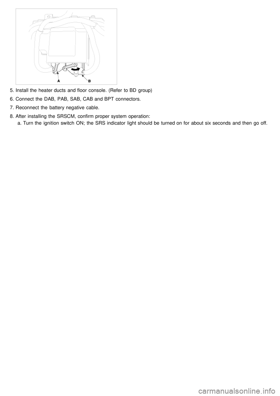
5.Install the heater ducts and floor console. (Refer to BD group)
6. Connect the DAB, PAB, SAB, CAB and BPT connectors.
7. Reconnect the battery negative cable.
8. After installing the SRSCM, confirm proper system operation:
a. Turn the ignition switch ON; the SRS indicator light should be turned on for about six seconds and then go off.
Page 823 of 1575

2007 > 2.7L V6 GASOLINE >
removal
a.Removal of the airbag must be performed according to the precautions/ procedures described previously.
b. Before disconnecting the front impact sensor connector, disconnect the front airbag connector(s).
c. Do not turn the ignition switch ON and do not connect the battery cable while replacing the front impact
sensor.
1. Disconnect the battery negative cable, and wait for at least three minutes before beginning work.
2. Disconnect Front Impact Sensor conncetor.
3. Remove the FIS mounting bolt then remove the Front Impact Sensor.
INSTALLATION
a.Ensure that the harness is installed and routed properly to prevent damage to the wiring.
b. Do not turn the ignition switch ON and do not connect the battery cable while replacing the front impact
sensor.
1. Install the new Front Impact Sensor with bolt then connect the SRS harness connector to the Front Impact Sensor.
Tightening torque
: 1.0 ~ 1.4 kgf.m (9.5 ~ 13.6 Nm, 7.0 ~ 10.0 lb.ft)
2. Reconnect the negative battery cable.
3. After installing the Front Impact Sensor, confirm proper system operation: Turn the ignition switch ON the SRS
indicator light should be turned on for about six seconds and then go off.
Page 828 of 1575

a.Ensure that the harness is installed and routed properly to prevent damage to the wiring.
b. Do not turn the ignition switch ON and do not connect the battery cable while replacing the side impact
sensor.
1. Install the new Side Impact Sensor with the bolt then connect the SRS harness connector to the Side Impact
Sensor.
Tightening torque
: 1.0 ~ 1.4 kgf.m (9.5 ~ 13.6 Nm, 7.0 ~ 10.0 lb.ft)
2.Install the center pillar trim. (Refer to BD group)
3. Install the door scuff trim. (Refer to BD group)
4. Reconnect the battery negative cable.
5. After installing the Side Impact Sensor, confirm proper system operation: Turn the ignition switch ON, the SRS
indicator light should be turned on for about six seconds and then go off.
REAR SIDE IMPACT SENSOR
1.Be sure that the battery negative cable is disconnected.
2. Install the new Side Impact Sensor with the bolt then connect the SRS harness connector to the Side Impact
Sensor.
Tightening torque
: 1.0 ~ 1.4 kgf.m (9.5 ~ 13.6 Nm, 7.0 ~ 10.0 lb.ft)
3.Install the rear pillar trim. (Refer to BD group)
4. Reconnect the battery negative cable.
5. After installing the Side Impact Sensor, confirm proper system operation: Turn the ignition switch ON, the SRS
indicator light should be turned on for about six seconds and then go off.
Page 836 of 1575

2.Remove ignition key from the vehicle.
3. Connect the clock spring harness connetor and horn harness connector to the clock spring.
4. Set the clock spring on neutral position and after turning the front wheels to the straight- ahead position, install the
clock spring.
5. Install the steering wheel column cover and the steering wheel. (Refer to ST group)
6. Connect the Driver Airbag (DAB) module connector and horn connector, then install the Driver Airbag (DAB)
module on the steering wheel.
7. Secure the Driver Airbag (DAB) with the new mounting bolts.
Tightening Torque (DAB Mounting Bolt)
: 0.8 ~ 1.1 kgf.m (7.9 ~ 10.8 Nm, 5.8 ~ 8.0 lb.ft)
8.Connect the battery negative cable.
9. After installing the airbag, confirm proper system operation:
a. Turn the ignition switch ON; the SRS indicator light should be turned on for about six seconds and then go off.
b. Make sure horn button works.
INSPECTION
Driver Airbag (DAB)
If any improper parts are found during the following inspection, replace the airbag module with a new one.
Never attempt to measure the circuit resistance of the airbag module (squib) even if you are using the specified
tester. If the circuit resistance is measured with a tester, accidental airbag deployment will result in serious
personal injury.
1. Check pad cover for dents, cracks or deformities.
2. Check the airbag module for denting, cracking or deformation.
3. Check hooks and connectors for damage, terminals for deformities, and harness for binds.
Page 842 of 1575

INSTALLATION
1.Disconnect the negative ( - ) cable from battery and wait for at least three minutes.
2. Remove ignition key from the vehicle.
3. Place a Passenger Airbag (PAB) on the crash pad and tighten the Passenger Airbag (PAB) mounting nuts.
Tightening Torque
: 0.7 ~ 0.8 kgf.m (7.0 ~ 8.0 N.m, 5.2 ~ 5.9 lb.ft)
4. Install the heater duct to the crash pad.
5. Install the crash pad. (Refer to BD group)
6. Tighten the PAB mounting bolts.
Tightening Torque
: 1.2 ~ 1.3 kgf.m (12.0 ~ 13.0 N.m, 8.9 ~ 9.6 lb.ft)
7. Connect the Passenger Airbag (PAB) harness connector to the SRS main harness connector.
8. Reinstall the bolve box. (Refer to BD group)
9. Reconnect the battery negative cable.
10. After installing the Passenger Airbag (PAB), confirm proper system operation:
a. Turn the ignition switch ON; the SRS indicator light should be turned on for about six seconds and then go off.