key KIA CARNIVAL 2007 Repair Manual
[x] Cancel search | Manufacturer: KIA, Model Year: 2007, Model line: CARNIVAL, Model: KIA CARNIVAL 2007Pages: 1575, PDF Size: 44.86 MB
Page 1236 of 1575

Battery Removal
a.If the battery is removed with the system in the ARM state, the system will be placed into the ARM state upon
battery reconnect.
b. The ALARM state will be re- activated if the battery is disconnected, then reconnected, with the system in an
ALARM state.
c. If the battery is disconnected and reconnected with the system in AFTER ALARM state, the alarm will be re-
activated.
d. The system will enter DISARM mode if the battery is disconnected during the ALARM WAIT state.
Panic
a.If RKE PANIC signal is received, Siren output and hazard lamp operate for 27 seconds and the system return to
the previous state as soon as the PANIC function finishes.
b. The PANIC function will be stopped if any RKE signal is received during PANIC activation..
c. If Key reminder switch is ON during PANIC function is operating, PANIC is stopped immediately.
d. If the system goes to ALARM mode during PANIC function is operating, PANIC is stopped immediately and then
ALARM function should be activated.
e. During ALARM state;
If RKE PANIC signal is received, ALARM mode is maintained and PANIC function should be ignored. ALARM has
higher priority than PANIC function.
f. During AFTER_ALARM state;
If RKE PANIC signal is received, AFTR_ALARM mode is maintained and PANIC function should be activated.
Safe & Rescue Mode
The goal of those modes is to be able to cope with failures that may happen on some of the most critical
functionalities (for the driver security) of the system.
Safe Mode
The safe mode is entered in case of system problems such as:
a. Incoherent inputs on monitored signals. In this case, safe mode is the debouncing time before the inputs are
considered INVALID. Note that today, we have no way to detect if the rain/light sensor is in working operation or
not. It means that a driver action will be required in case of failure of this sensor;
b. Loss of the CAN frame containing the monitored signal:
c. Loss of the CAN network: CAN goes to BUS OFF state, safe mode is the time necessary for detecting the BUS
OFF state.
In all cases, the action in safe mode is to maintain the previous state of the system (for lighting and wiping). The list of
monitored signals is the same as in rescue mode
Exiting Safe Mode
The software safe mode is exited and the module goes back to the normal mode when: a. On IPM, hardware inputs return to a coherent state;
b. The lost CAN signal comes back while timeout has not elapsed;
c. The CAN network returns to a normal state without reaching BUS OFF state.
Software safe mode is also exited when the software rescue mode is entered (problem does not disappear).
Hardware safe mode is exited and the module goes back to normal mode if the internal problem disappears (watchdog
is properly triggered again). If the problem stays, hardware safe mode is exited to enter hardware rescue mode.
Rescue Modes
The rescue mode consists in activating some safety functions when IGN2 = ON: a. Switch on the low beams (FAM), park lamps (FAM), tail lamps (RAM) and cluster backlighting (IPM);
b. Unlock of all the doors when the rescue mode is entered with IGN2 = ON
c. Front wipers do not need to be turned on by software in rescue mode because wipers can be turned on by
manually setting the MF switch to low speed. The FAM software must keep the same state as before entering the
rescue mode.
d. When IGN2 = OFF, low beams, park/tail lamps and cluster backlighting are turned off.
Entering Rescue Modes
Page 1241 of 1575
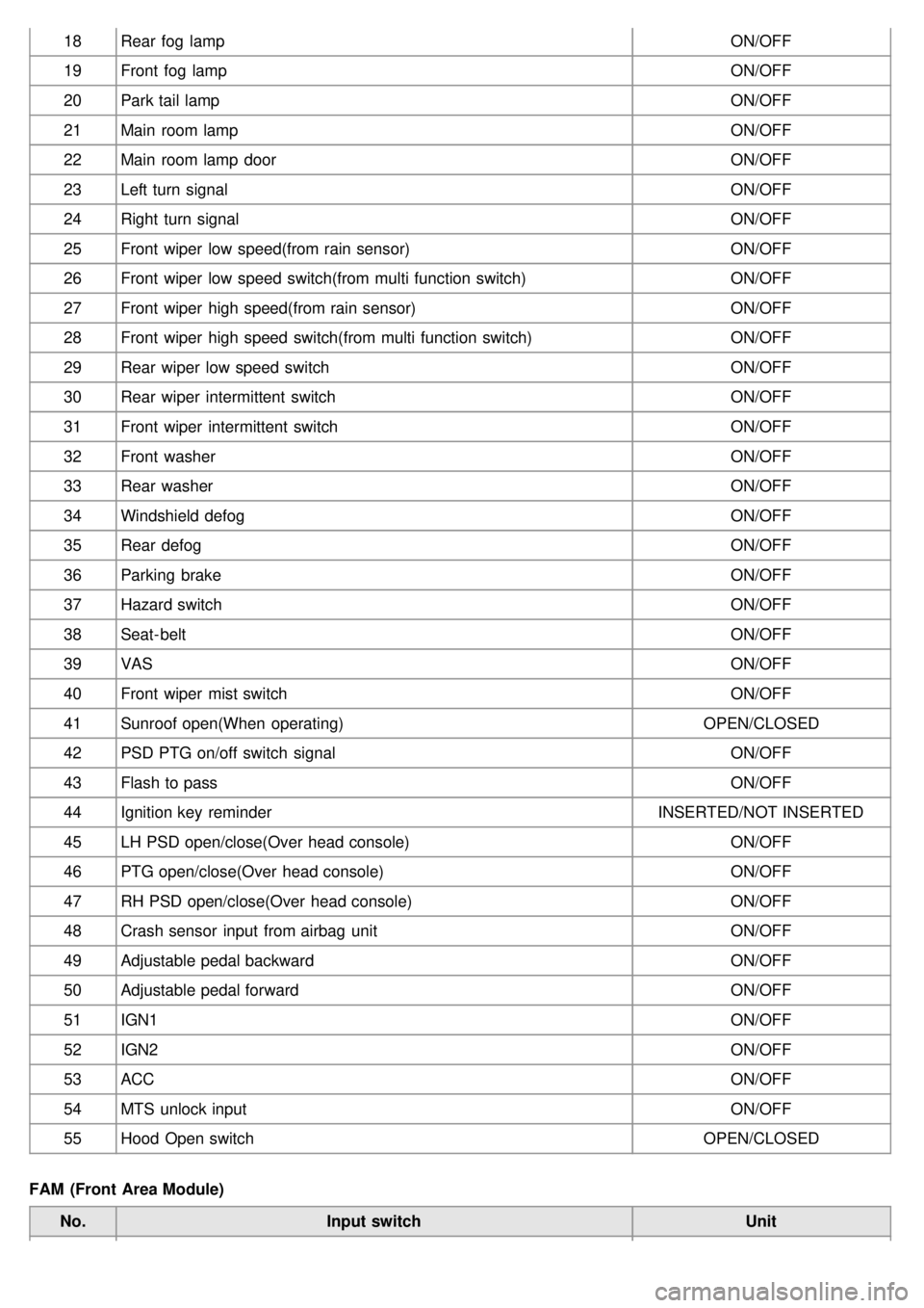
18Rear fog lamp ON/OFF
19 Front fog lamp ON/OFF
20 Park tail lamp ON/OFF
21 Main room lamp ON/OFF
22 Main room lamp door ON/OFF
23 Left turn signal ON/OFF
24 Right turn signal ON/OFF
25 Front wiper low speed(from rain sensor) ON/OFF
26 Front wiper low speed switch(from multi function switch) ON/OFF
27 Front wiper high speed(from rain sensor) ON/OFF
28 Front wiper high speed switch(from multi function switch) ON/OFF
29 Rear wiper low speed switch ON/OFF
30 Rear wiper intermittent switch ON/OFF
31 Front wiper intermittent switch ON/OFF
32 Front washer ON/OFF
33 Rear washer ON/OFF
34 Windshield defog ON/OFF
35 Rear defog ON/OFF
36 Parking brake ON/OFF
37 Hazard switch ON/OFF
38 Seat- belt ON/OFF
39 VAS ON/OFF
40 Front wiper mist switch ON/OFF
41 Sunroof open(When operating) OPEN/CLOSED
42 PSD PTG on/off switch signal ON/OFF
43 Flash to pass ON/OFF
44 Ignition key reminder INSERTED/NOT INSERTED
45 LH PSD open/close(Over head console) ON/OFF
46 PTG open/close(Over head console) ON/OFF
47 RH PSD open/close(Over head console) ON/OFF
48 Crash sensor input from airbag unit ON/OFF
49 Adjustable pedal backward ON/OFF
50 Adjustable pedal forward ON/OFF
51 IGN1 ON/OFF
52 IGN2 ON/OFF
53 ACC ON/OFF
54 MTS unlock input ON/OFF
55 Hood Open switch OPEN/CLOSED
FAM (Front Area Module) No. Input switch Unit
Page 1242 of 1575
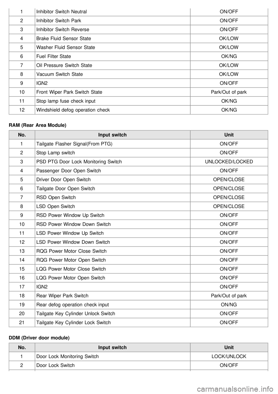
1Inhibitor Switch Neutral ON/OFF
2 Inhibitor Switch Park ON/OFF
3 Inhibitor Switch Reverse ON/OFF
4 Brake Fluid Sensor State OK/LOW
5 Washer Fluid Sensor State OK/LOW
6 Fuel Filter State OK/NG
7 Oil Pressure Switch State OK/LOW
8 Vacuum Switch State OK/LOW
9 IGN2 ON/OFF
10 Front Wiper Park Switch State Park/Out of park
11 Stop lamp fuse check input OK/NG
12 Windshield defog operation check OK/NG
RAM (Rear Area Module) No. Input switch Unit
1 Tailgate Flasher Signal(From PTG) ON/OFF
2 Stop Lamp switch ON/OFF
3 PSD PTG Door Lock Monitoring Switch UNLOCKED/LOCKED
4 Passenger Door Open Switch ON/OFF
5 Driver Door Open Switch OPEN/CLOSE
6 Tailgate Door Open Switch OPEN/CLOSE
7 RSD Open Switch OPEN/CLOSE
8 LSD Open Switch OPEN/CLOSE
9 RSD Power Window Up Switch ON/OFF
10 RSD Power Window Down Switch ON/OFF
11 LSD Power Window Up Switch ON/OFF
12 LSD Power Window Down Switch ON/OFF
13 RQG Power Motor Close Switch ON/OFF
14 RQG Power Motor Open Switch ON/OFF
15 LQG Power Motor Close Switch ON/OFF
16 LQG Power Motor Open Switch ON/OFF
17 IGN2 ON/OFF
18 Rear Wiper Park Switch Park/Out of park
19 Rear defog operation check input ON/NG
20 Tailgate Key Cylinder Unlock Switch ON/OFF
21 Tailgate Key Cylinder Lock Switch ON/OFF
DDM (Driver door module) No. Input switch Unit
1 Door Lock Monitoring Switch LOCK/UNLOCK
2 Door Lock Switch ON/OFF
Page 1243 of 1575
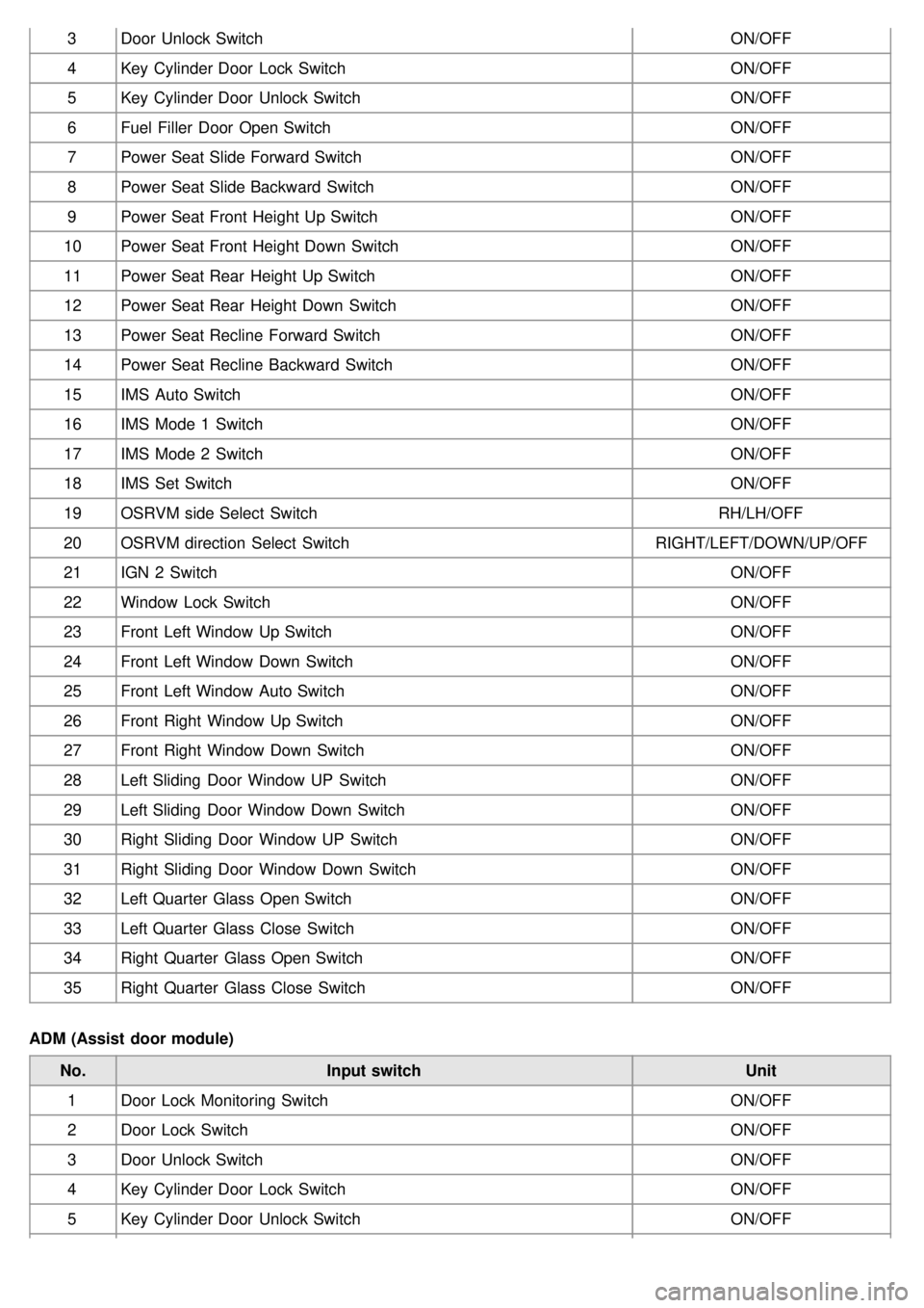
3Door Unlock Switch ON/OFF
4 Key Cylinder Door Lock Switch ON/OFF
5 Key Cylinder Door Unlock Switch ON/OFF
6 Fuel Filler Door Open Switch ON/OFF
7 Power Seat Slide Forward Switch ON/OFF
8 Power Seat Slide Backward Switch ON/OFF
9 Power Seat Front Height Up Switch ON/OFF
10 Power Seat Front Height Down Switch ON/OFF
11 Power Seat Rear Height Up Switch ON/OFF
12 Power Seat Rear Height Down Switch ON/OFF
13 Power Seat Recline Forward Switch ON/OFF
14 Power Seat Recline Backward Switch ON/OFF
15 IMS Auto Switch ON/OFF
16 IMS Mode 1 Switch ON/OFF
17 IMS Mode 2 Switch ON/OFF
18 IMS Set Switch ON/OFF
19 OSRVM side Select Switch RH/LH/OFF
20 OSRVM direction Select Switch RIGHT/LEFT/DOWN/UP/OFF
21 IGN 2 Switch ON/OFF
22 Window Lock Switch ON/OFF
23 Front Left Window Up Switch ON/OFF
24 Front Left Window Down Switch ON/OFF
25 Front Left Window Auto Switch ON/OFF
26 Front Right Window Up Switch ON/OFF
27 Front Right Window Down Switch ON/OFF
28 Left Sliding Door Window UP Switch ON/OFF
29 Left Sliding Door Window Down Switch ON/OFF
30 Right Sliding Door Window UP Switch ON/OFF
31 Right Sliding Door Window Down Switch ON/OFF
32 Left Quarter Glass Open Switch ON/OFF
33 Left Quarter Glass Close Switch ON/OFF
34 Right Quarter Glass Open Switch ON/OFF
35 Right Quarter Glass Close Switch ON/OFF
ADM (Assist door module) No. Input switch Unit
1 Door Lock Monitoring Switch ON/OFF
2 Door Lock Switch ON/OFF
3 Door Unlock Switch ON/OFF
4 Key Cylinder Door Lock Switch ON/OFF
5 Key Cylinder Door Unlock Switch ON/OFF
Page 1248 of 1575
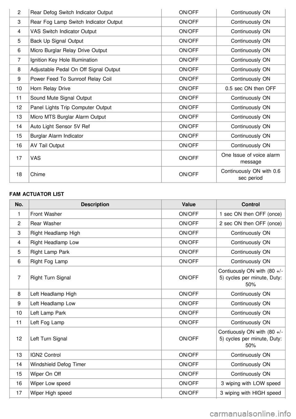
2Rear Defog Switch Indicator Output ON/OFFContinuously ON
3 Rear Fog Lamp Switch Indicator Output ON/OFFContinuously ON
4 VAS Switch Indicator Output ON/OFFContinuously ON
5 Back Up Signal Output ON/OFFContinuously ON
6 Micro Burglar Relay Drive Output ON/OFFContinuously ON
7 Ignition Key Hole Illumination ON/OFFContinuously ON
8 Adjustable Pedal On Off Signal Output ON/OFFContinuously ON
9 Power Feed To Sunroof Relay Coil ON/OFFContinuously ON
10 Horn Relay Drive ON/OFF0.5 sec ON then OFF
11 Sound Mute Signal Output ON/OFFContinuously ON
12 Panel Lights Trip Computer Output ON/OFFContinuously ON
13 Micro MTS Burglar Alarm Output ON/OFFContinuously ON
14 Auto Light Sensor 5V Ref ON/OFFContinuously ON
15 Burglar Alarm Indicator ON/OFFContinuously ON
16 AV Tail Output ON/OFFContinuously ON
17 VAS ON/OFFOne Issue of voice alarm
message
18 Chime ON/OFFContinuously ON with 0.6
sec period
FAM ACTUATOR LIST No. Description ValueControl
1 Front Washer ON/OFF1 sec ON then OFF (once)
2 Rear Washer ON/OFF2 sec ON then OFF (once)
3 Right Headlamp High ON/OFFContinuously ON
4 Right Headlamp Low ON/OFFContinuously ON
5 Right Lamp Park ON/OFFContinuously ON
6 Right Fog Lamp ON/OFFContinuously ON
7 Right Turn Signal ON/OFFContiuously ON with (80 +/ -
5) cycles per minute, Duty: 50%
8 Left Headlamp High ON/OFFContinuously ON
9 Left Headlamp Low ON/OFFContinuously ON
10 Left Lamp Park ON/OFFContinuously ON
11 Left Fog Lamp ON/OFFContinuously ON
12 Left Turn Signal ON/OFFContiuously ON with (80 +/ -
5) cycles per minute, Duty: 50%
13 IGN2 Control ON/OFFContinuously ON
14 Windshield Defog Timer ON/OFFContinuously ON
15 Wiper On Off ON/OFFContinuously ON
16 Wiper Low speed ON/OFF3 wiping with LOW speed
17 Wiper High speed ON/OFF3 wiping with HIGH speed
Page 1251 of 1575
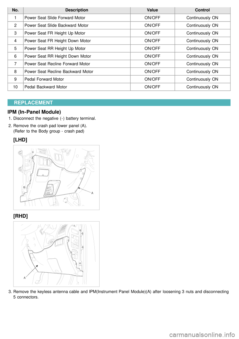
No.Description ValueControl
1 Power Seat Slide Forward Motor ON/OFFContinuously ON
2 Power Seat Slide Backward Motor ON/OFFContinuously ON
3 Power Seat FR Height Up Motor ON/OFFContinuously ON
4 Power Seat FR Height Down Motor ON/OFFContinuously ON
5 Power Seat RR Height Up Motor ON/OFFContinuously ON
6 Power Seat RR Height Down Motor ON/OFFContinuously ON
7 Power Seat Recline Forward Motor ON/OFFContinuously ON
8 Power Seat Recline Backward Motor ON/OFFContinuously ON
9 Pedal Forward Motor ON/OFFContinuously ON
10 Pedal Backward Motor ON/OFFContinuously ON
REPLACEMENT
IPM (In-Panel Module)
1. Disconnect the negative ( - ) battery terminal.
2. Remove the crash pad lower panel (A).
(Refer to the Body group - crash pad)
[LHD]
[RHD]
3.Remove the keyless antenna cable and IPM(Instrument Panel Module)(A) after loosening 3 nuts and disconnecting
5 connectors.
Page 1259 of 1575

2007 > 2.7L V6 GASOLINE >
DESCRIPTION
An optimal seat position set by a driver can be memorized in P/seat unit by memory SW and position SW, which
enables restoration of seat position set by the driver despite seat adjustments.
Furthermore, data is transmitted between P/seat and IPM, DDM, ADM, RAM, FAM, CLUSTER through CAN BUS.
Seat position presets cannot be recalled while driving. An emergency stop function is provided; additional functions are
described below.
1. It conducts manual operation of seat by CAN BUS data transmitted by DDM as well as that of adjustable pedal by
CAN BUS data transmitted by IPM received when operating SW manually.
2. Manual SW behavior when communication stops (back- up behavior)
a. Slide front/rear
b. Recline front/rear
c. Position control of slide motor is possible by manual SW even in case of congestion in CPU or removal of a
fuse for P/seat unit B.
3. 2 memory locations are provided for storing seat, outside mirror, and adjustable pedal presets.
4. The driver seat can be set to slide rearward when the ignition key is removed, and forward when the key is
inserted.
5. 2 additional presets for seat, mirror, and adjustable pedal position can be stored with the RKE transmitter.
OPERATION
MANUAL OPERATION
Manual operation of the driver seat and adjustable pedals is possible provided the transaxle is in 'P' range and the
vehicle speed is 0 MPH. Operation of the manual controls overrides any automatic operation commanded via CAN.
MEMORY OPERATION
1. Pressing the 'M' button on the control panel will place the system into memory storage mode and will result in a
single pulse from the output buzzer.
2. If one of the memory location buttons is pressed and held within 5 seconds of pressing the 'M' button, the output
buzzer will pulse twice to indicate successful storage of seat, mirror, and adjustable pedal positions.
3. The ignition switch must be in the RUN or START position, the vehicle speed must be 0 MPH, and the transaxle
must be in 'P' range to store memory presets.
4. Pressing the 'M' button while recalling a stored preset will halt the preset recall operation.
5. Memory will be cleared if battery is removed.
MEMORY REPLAY OPERATION
1.Pressing one of the memory location buttons will result in the driver seat, outside mirrors, and adjustable pedals
being positioned based on the stored preset data.
2. The ignition switch must be in the RUN position, the transaxle must be in 'P' range, the vehicle speed must be 0
MPH, and the manual functions must not be in operation to recall stored presets.
3. Others
a. Play operation not recorded in the position switch will not be conducted and there will be no buzzer output.
b. If other data is received during preset recall operation, the most recent preset recall signal will take
precedence.
c. If engine is started during preset recall operation, halt preset recall operation, and resume it toward target
position 100ms after Ignition switch is returned to "RUN". However, if the START state lasts over 5 sec., it will
not resume even after returning to RUN.
d. If preset recall order is received during engine start, preset recall operation is inhibited.
e. If input from manual switch for seat and adjust pedal occurs during preset recall operation of seat and adjust
pedal, halt all their preset recall operations.
f. If an error occurs during manual operation of seat and adjust pedal, delete Memory.
Page 1260 of 1575
4.Operation control
a. Prioritization of operations
Motor starting is delayed for 100ms respectively in case of auto control to prevent rush current from overlap
when motors are running, and it follows the following order.
Slide > recline > front height > rear height > adjust pedal
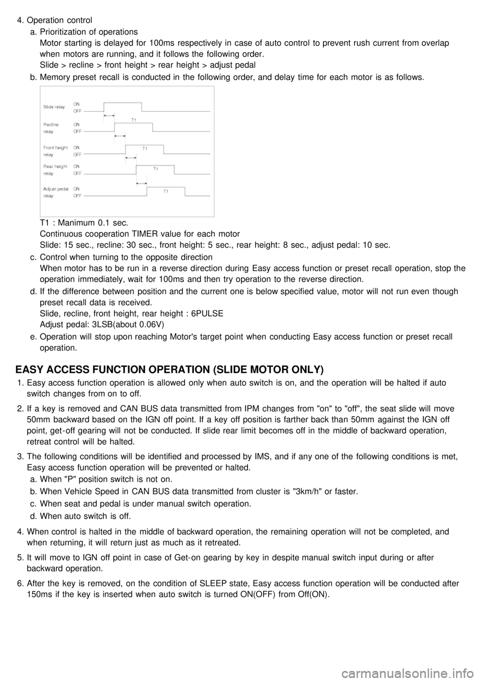
b. Memory preset recall is conducted in the following order, and delay time for each motor is as follows.
T1 : Manimum 0.1 sec.
Continuous cooperation TIMER value for each motor
Slide: 15 sec., recline: 30 sec., front height: 5 sec., rear height: 8 sec., adjust pedal: 10 sec.
c. Control when turning to the opposite direction
When motor has to be run in a reverse direction during Easy access function or preset recall operation, stop the
operation immediately, wait for 100ms and then try operation to the reverse direction.
d. If the difference between position and the current one is below specified value, motor will not run even though
preset recall data is received.
Slide, recline, front height, rear height : 6PULSE
Adjust pedal: 3LSB(about 0.06V)
e. Operation will stop upon reaching Motor's target point when conducting Easy access function or preset recall
operation.
EASY ACCESS FUNCTION OPERATION (SLIDE MOTOR ONLY)
1.Easy access function operation is allowed only when auto switch is on, and the operation will be halted if auto
switch changes from on to off.
2. If a key is removed and CAN BUS data transmitted from IPM changes from "on" to "off", the seat slide will move
50mm backward based on the IGN off point. If a key off position is farther back than 50mm against the IGN off
point, get - off gearing will not be conducted. If slide rear limit becomes off in the middle of backward operation,
retreat control will be halted.
3. The following conditions will be identified and processed by IMS, and if any one of the following conditions is met,
Easy access function operation will be prevented or halted.
a. When "P" position switch is not on.
b. When Vehicle Speed in CAN BUS data transmitted from cluster is "3km/h" or faster.
c. When seat and pedal is under manual switch operation.
d. When auto switch is off.
4. When control is halted in the middle of backward operation, the remaining operation will not be completed, and
when returning, it will return just as much as it retreated.
5. It will move to IGN off point in case of Get- on gearing by key in despite manual switch input during or after
backward operation.
6. After the key is removed, on the condition of SLEEP state, Easy access function operation will be conducted after
150ms if the key is inserted when auto switch is turned ON(OFF) from Off(ON).
Page 1261 of 1575

MEMORY STORAGE OPERATION BY KEYLESS
1.If "ID1" or "ID2" is received during keyless lock operation, record seat and pedal position in keyless code. (there is
no buzzer output during memory storage operation by keyless)
2. Memory storage operation is allowed for a single ID after a change of IG from "on" →"off".
3. Any one of the following conditions will prevent keyless Memory storage operation.
a. When "P" position switch is not on.
b. When Vehicle Speed in CAN BUS data transmitted from CLUSTER is "3km/h" or faster.
c. When seat and pedal is manipulated by CAN BUS and manual switch.
d. When IG transmitted from IPM is other than off.
PRESET RECALL OPERATION BY KEYLESS
1.When IG is off (CAN BUS data IG transmitted from IPM is "off") and a key is removed (CAN BUS data Key
Reminder Switch transmitted from IPM is "off"), and if "ID1" or "ID2" is received during keyless unlock operation, it
automatically adjusts seat and pedal positions as memorized in keyless code (there is no buzzer output during
preset recall operation by keyless). However, seat slide adjustment position is determined as follows, depending on
Auto switch.
a. When auto switch is on ("IMS Auto Switch" is "on") , the position is automatically adjusted to 50 mm farther
back than target position, and if a key is inserted ("Key Reminder Switch" changes from "off" to "on"), it
conducts Get- on gearing operation to a target preset recall position.
b. If auto switch is off ("IMS Auto Switch" is "off"), it moves to the target memory play position.
2. Any one of the following conditions will prevent preset recall operation.
a. When "P" position switch is not on.
b. When Vehicle Speed in CAN BUS data transmitted from cluster is "3km/h" or faster.
c. When seat and pedal is manipulated by CAN BUS and manual switch.
d. When IG Switch transmitted from IPM is other than off.
e. When a key is inserted.
3. Playing will be halted during preset recall operation if any of the following conditions is met.
a. When "P" position switch is not on.
b. When vehicle speed in CAN BUS data transmitted from cluster is "3km/h" or faster.
c. When seat and pedal is manipulated by CAN BUS and manual switch.
SETTING LIMIT
1.A limit switch is installed to prevent the seat from traveling beyond the maximum forward/reward positions.
2. No limit switch is installed for the recline, height, or pedal adjustments. Arbitrary limit positions are used for these
functions.
DETECTING ERRORS FOR SEAT
Take countermeasure against error if the following conditions occur during manual switch operation.
a. Error when pulse is not fed.
SlideReclineFront height Rear height
Page 1302 of 1575

2007 > 2.7L V6 GASOLINE >
INSPECTION
FRONT BLOWER
Check for continuity between the terminals. 1. There should be continuity between the No.1 in the ICM- A and No.10 in the ICM- B terminals when power and
ground are connected to the No.7 in the ICM- A and No.13 terminals in the ICM- B terminals.
2. There should be no continuity between the No.1 in the ICM- A and No.10 terminals in the ICM- B terminals when
power is disconnected.
REAR BLOWER
Check for continuity between the terminals.
1. There should be continuity between the No.4 in the ICM- A and No.12 in the ICM- B terminals when power and
ground are connected to the No.2 in the ICM- A and No.14 terminals in the ICM- B terminals.
2. There should be no continuity between the No.4 in the ICM- A and No.12 in the ICM- B terminals when power is
disconnected.
SEAT HEATER RELAYS
Check for continuity between the terminals.
1. There should be continuity between the No.9 and No.6 terminals when power and ground are connected to the
No.7 and No.8 terminals in the ICM- B.
2. There should be no continuity between the No.9 and No.6 terminals when power is disconnected.
KEY INTERLOCK
Check for continuity between the terminals.
1. There should be continuity between the No.2 and No.3 terminals when power and ground are connected to the
No.4 and No.5 terminals in the ICM- B.
2. There should be no continuity between the No.2 and No.3 terminals when power is disconnected.