Bulb KIA CARNIVAL 2007 Workshop Manual
[x] Cancel search | Manufacturer: KIA, Model Year: 2007, Model line: CARNIVAL, Model: KIA CARNIVAL 2007Pages: 1575, PDF Size: 44.86 MB
Page 240 of 1575

Faults with the following items will illuminate the MILa. Heated oxygen sensor (HO2S)
b. Mass Air Flow sensor (MAFS)
c. Throttle position sensor (TPS)
d. Engine coolant temperature sensor (ECTS)
e. Idle speed control actuator (ISCA)
f. Injectors
g. ECM
Refer to "INSPECTION CHART FOR DIAGNOSTIC TROUBLE CODES (DTC)" for more information.
1. After turning ON the ignition key, ensure that the light illuminates for about 5 seconds and then goes out.
2. If the light does not illuminate, check for an open circuit in the harness, a blown fuse or a blown bulb.
Self-Diagnosis
If a sensor connector is disconnected with the ignition switch turned on, the diagnostic trouble code (DTC) is
recorded. In this case, disconnect the battery negative terminal ( - ) for 15 seconds or more, and the diagnosis
memory will be erased.
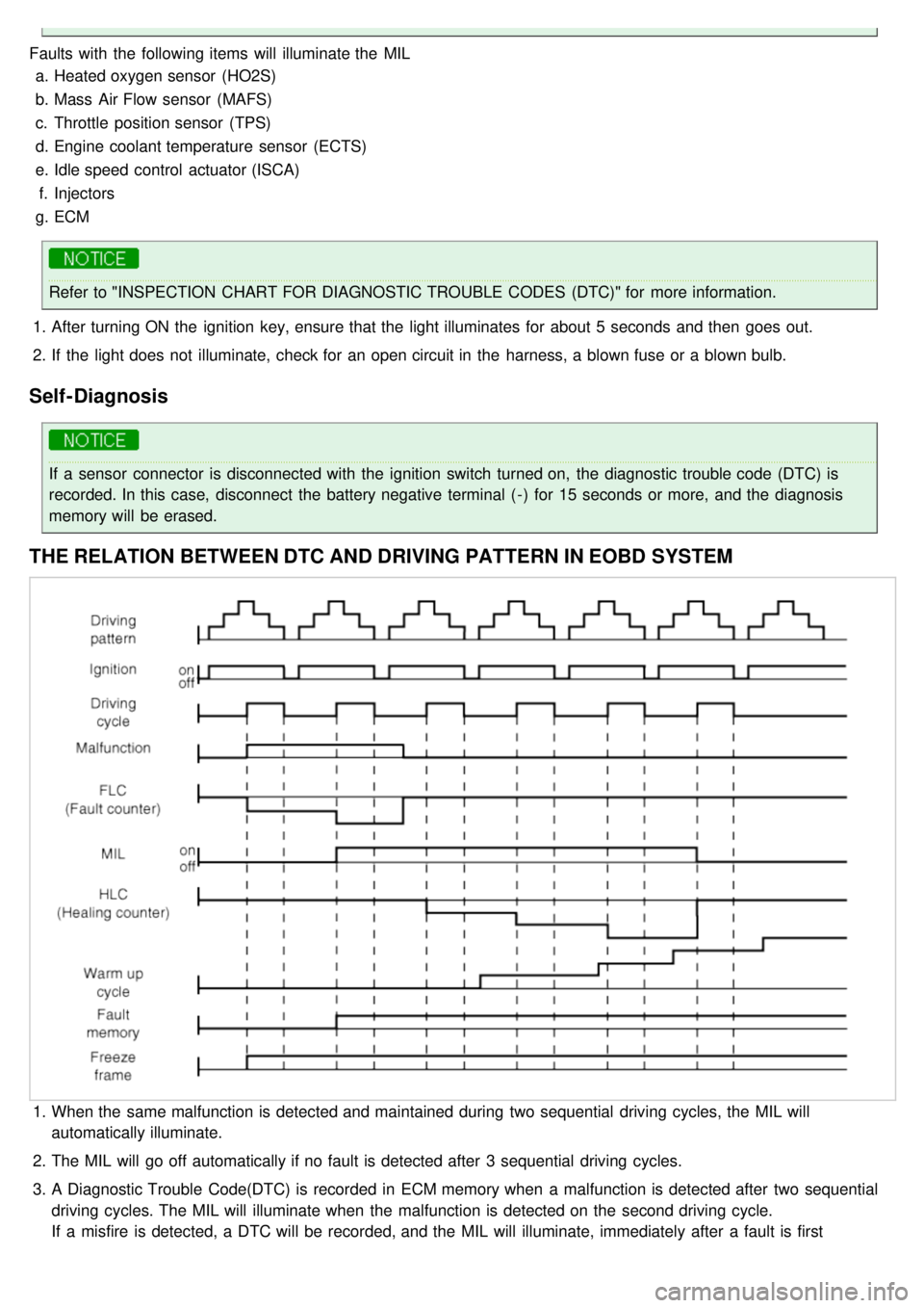
THE RELATION BETWEEN DTC AND DRIVING PATTERN IN EOBD SYSTEM
1.When the same malfunction is detected and maintained during two sequential driving cycles, the MIL will
automatically illuminate.
2. The MIL will go off automatically if no fault is detected after 3 sequential driving cycles.
3. A Diagnostic Trouble Code(DTC) is recorded in ECM memory when a malfunction is detected after two sequential
driving cycles. The MIL will illuminate when the malfunction is detected on the second driving cycle.
If a misfire is detected, a DTC will be recorded, and the MIL will illuminate, immediately after a fault is first
detected.
Page 797 of 1575

2007 > 2.7L V6 GASOLINE >
WARNING LAMP ACTIVATION
WARNING LAMP BEHAVIOR AFTER IGNITION ON
As soon as the operating voltage is applied to the SRSCM ignition input, the SRSCM activates the warning lamp for a
bulb check.
The lamp shall turn on for 6 seconds during the initialization phase and be turned off afterward. However, in order to
indicate the driver, the warning lamp shall turn on for 6 seconds and off for one second then on continuously after the
operating voltage is applied if any active fault exists. 1. Active fault or historical fault counter is greater or equal to 10
2.Normal or historical fault counter is less than 10
SRSCM INDEPENDENT WARNING LAMP ACTIVATION
There are certain fault conditions in which the SRSCM cannot function and thus cannot control the operation of the
standard warning lamp. In these cases, the standard warning lamp is directly activated by appropriate circuitry that
operates independently of the SRSCM. These cases are:
1. Loss of battery supply to the SRSCM : warning lamp turned on continuously.
2. Loss of internal operating voltage : warning lamp turned on continuously.
3. Loss of Microprocessor operation : warning lamp turned on continuously.
4. SRSCM not connected : warning lamp turned on continuously through the shorting bar.
PASSENGER AIRBAG DEACTIVATION (PAD) LAMP OPERATION
The SRSCM is designed with circuitry and software to drive a PAD lamp, which is used for depowered airbag system.
For the PAD indicator circuitry to function properly, both the SRSCM and PAD indicator are sourced from the same
ignition line. After ignition on, the PAD indicator will be turned on for 4 seconds and off for 3 seconds during the
initialization phase. Thereafter the lamp will be turned on as long as the PAD switch is in the disabled position.
PASSENGER RESTRAINTS ACTIVATION WITH PAD SWITCH
The PAD switch affects the activation of the front passenger airbag only and the switch is controlled manually. The
PAD switch will be functioned as follows:
PAD Switch status PAD LampPAB
Phase- up ON → OFF Enable
Enabled position OFFEnable
Disabled position ONDisable
Fault Based on PABEnable
Page 942 of 1575

DETECTING CONDITIONTrouble Symptoms Possible Cause
When current flows in the HECU the ABS warning lamp turns from
ON to OFF as the initial check.Therefore if the lamp does not light up,
the cause may be an open in the lamp power supply circuit, a blown
bulb, an open in the both circuits between the ABS warning lamp and
the HECU, and the inoperative HECU. a.
Inoperative ABS warning lamp bulb
b. Blown No.2 fuse (10A) in the engine
compartment junction block
c. Inoperative ABS warning lamp module
d. Inoperative HECU
INSPECTION PROCEDURES
PROBLEM VERIFICATION
Disconnect the connector from the ABS control module and turn the ignition switch ON.
Does the ABS warning lamp light up?
▶ It is normal. Recheck the ABS control module.
▶ Check the power source for the ABS warning lamp.
CHECK THE POWER SOURCE FOR THE ABS WARNING LAMP
1. Disconnect the instrument cluster connector and turn the ignition switch ON.
2. Measure the voltage between terminal 8 of the cluster harness side connector and body ground.
Specification: approximately B+
Is voltage within specification?
▶ Repair bulb or instrument cluster assembly.
▶ Check for blown fuse.
Page 1229 of 1575

switch, the status of the ABS EBD warning, the status of the brake fluid sensor and the speed of the vehicle.
The IPM sends the park brake indicator control on the CAN network.
The indicator is lighted if the vacuum switch or ABS EBD warning are on or brake fluid sensor is low or park brake
switch is on.
If the speed of the vehicle is over 10 km/h and ignition switch is on the status RUN the park brake indicator control is
blinking at 50% duty in 0.6 second if Parking Brake switch Input is active. In this case Vacuum switch, ABS EBD
warning and Brake Fluid sensor are ignored.
The park brake indicator is blinking on the same time that the chime is ringing. If a CAN signal among Vacuum switch,
EBD warning or Brake Fluid Sens switch is INVALID, out of range or not received this CAN signal is considered to be
OFF.
If VehicleSpeed CAN signal is INVALID or not received, it is considered to be 0 kph.
Charging Voltage Control
The IPM receives on analog input the voltage of generator and sends a warning.
When the voltage of generator L pass strictly above 10V, the state of the CAN variable.
Turn Indicators Status
The status of the turn indicators are sent on the CAN network when the CAN network is available.
High Beam Status
The status of the high beam is sent on the CAN network when the CAN network is available.
Front Fog Lamp Status
The status of the front fog lamp (lightning and state of the bulbs) is sent on the CAN network when the CAN network
is available.
Doors Open Warning
The RAM receives on digital input the status of the driver door open switch and sends it on the CAN network.
The RAM receives on digital input the status of the passenger door open switch and sends it on the CAN network.
The RAM receives on digital input the status of the left sliding door open switch and sends it on the CAN network.
The RAM receives on digital input the status of the right sliding door open switch and sends it on the CAN network.
When vehicle speed is under 10 kph, with ignition key not inserted and any door OPEN, DoorsOpenWngCtrl stays ON
for 20 min and then is turned OFF.
Tailgate Open Switch Status
When vehicle speed is under 10 kph, ignition key is inserted and Tailgate open switch is OPEN, Tailgate Open
warning stays ON forever (IPM can enter sleep mode).
When vehicle speed is under 10 kph, with ignition key not inserted and lgate open switch is OPEN, Tailgate Open
warning stays ON for 20 min and then is turned OFF.
Chime Control
1.The chime warns the driver that a problem is occurred.
These warning are:
a. Seat belt
b. Parking on
c. Over speed
d. Key reminder
e. Light Warning
f. Doors Open
g. Tailgate open warning
2. Chime sound priority:
a. 1st : Seatbelt warning
b. 2nd : Overspeed warning
c. 3rd : Door open warning
d. 4th : T/Gate open warning
e. 5th : Key operated warning
f. 6th : Parking Brake warning
Page 1467 of 1575

2007 > 2.7L V6 GASOLINE >
SPECIFICATION
Items Bulb Watt (W)
Head lamp (High)
Head lamp (Low)
Front turn signal lamp
Front position lamp
Front side marker lamp
Front fog lamp
Rear stop/tail lamp
Back up lamp
Rear turn signal lamp
Rear fog lamp
License plate lamp
Side repeater
Room lamp
Overhead console lamp
High mounted stop lamp
Glove box lamp
Luggage room lamp
Door courtesy lamp 55
55
28
8
5
35
21/5 16
27
215
5
10
10 x 2 LED 5
5
5
Page 1469 of 1575

2007 > 2.7L V6 GASOLINE >
REPLACEMENT
1.Disconnect the negative ( - ) battery terminal.
2. Loose the mounting bolts (2EA).
3.Remove the head lamp assembly after disconnecting the lamp connectors.
Take care that holding clip (A) is not to be damaged.
4.Remove the head lamp rear cover and pulling up head lamp bulb fixing wire clip.
5.Replace the bulb.
6. Installation is the reverse of removal.
HEAD LAMP AIMING INSTRUCTIONS
Alternately turn the adjusting gear to adjust the head lamp aiming. If beam- setting equipment is not available, proceed
as follows :
1. Inflate the tires to the specified pressure and remove any loads from the vehicle except the driver, spare tire, and
tools.
Page 1474 of 1575

2007 > 2.7L V6 GASOLINE >
REPLACEMENT
FRONT TURN SIGNAL LAMP
1. Disconnect the negative ( - ) battery terminal.
2. Remove front lamp assembly.
3. Remove the socket in a counterclockwise direction.
4.Replace the bulb (A).
REAR TURN SIGNAL LAMP
1.Disconnect the negative ( - ) battery terminal.
2. Remove the rear lamp assembly (A) after removing the mounting screw (3EA) and connector.
3.Remove the socket in a counterclockwise direction and replace the bulbs.
SIDE TURN SIGNAL LAMP
1.Disconnect the negative ( - ) battery terminal.
2. Disconnect the connector after removing the lens.
Page 1475 of 1575

3.Remove the socket in a counterclockwise direction.
4.Replace the bulb.
Page 1477 of 1575

2007 > 2.7L V6 GASOLINE >
REPLACEMENT
1.Disconnect the negative ( - ) battery terminal.
2. Detach the lamp lens from the room lamp with a flat- tip screwdriver ( - ) then replace the bulb.
3.Pull the bulb down and replace it with a new one.
Take care that holding clip (A) is not to be damaged.
4. Installation is the reverse of removal.
Page 1479 of 1575

2007 > 2.7L V6 GASOLINE >
REPLACEMENT
1.Disconnect the negative ( - ) battery terminal.
2. Replace the bulb after removing the lens with a flat- tip screwdriver.
3.Remove the bulb and replace it with a new one
Take care that holding clip (A) is not to be damaged