back up lamp KIA CARNIVAL 2007 Workshop Manual
[x] Cancel search | Manufacturer: KIA, Model Year: 2007, Model line: CARNIVAL, Model: KIA CARNIVAL 2007Pages: 1575, PDF Size: 44.86 MB
Page 421 of 1575
2007 > 2.7L V6 GASOLINE >
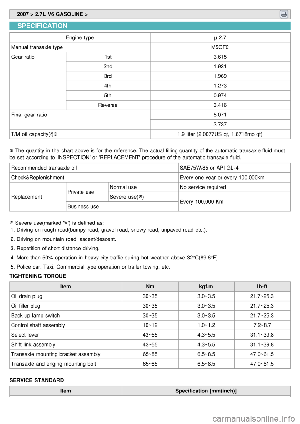
SPECIFICATION
Engine type µ 2.7
Manual transaxle type M5GF2
Gear ratio 1st 3.615
2nd 1.931
3rd 1.969
4th 1.273
5th 0.974
Reverse 3.416
Final gear ratio 5.071
3.737
T/M oil capacity(ℓ) ※ 1.9 liter (2.0077US qt, 1.6718mp qt)
※ The quantity in the chart above is for the reference. The actual filling quantity of the automatic transaxle fluid must
be set according to 'INSPECTION' or 'REPLACEMENT' procedure of the automatic transaxle fluid.
Recommended transaxle oil SAE75W/85 or API GL - 4
Check&Replenishment Every one year or every 100,000km
Replacement Private useNormal use
No service required
Severe use( ※)
Every 100,000 Km
Business use
※ Severe use(marked '※') is defined as:
1. Driving on rough road(bumpy road, gravel road, snowy road, unpaved road etc.).
2. Driving on mountain road, ascent/descent.
3. Repetition of short distance driving.
4. More than 50% operation in heavy city traffic during hot weather above 32°C(89.6°F).
5. Police car, Taxi, Commercial type operation or trailer towing, etc.
TIGHTENING TORQUE
Item Nmkgf.m lb- ft
Oil drain plug 30~353.0~3.521.7~25.3
Oil filler plug 30~353.0~3.521.7~25.3
Back up lamp switch 30~353.0~3.521.7~25.3
Control shaft assembly 10~121.0~1.2 7.2~8.7
Select lever 43~554.3~5.531.1~39.8
Shift link assembly 43~554.3~5.531.1~39.8
Transaxle mounting bracket assembly 65~856.5~8.547.0~61.5
Transaxle and enging mounting bolt 65~856.5~8.547.0~61.5
SERVICE STANDARD Item Specification [mm(inch)]
Page 424 of 1575

2007 > 2.7L V6 GASOLINE >
SERVICE ADJUSTMENT PROCEDURE
Transmission oil inspection and replacement
1. After parking the vehicle on a plain, stop the engine.
2. After removing the oil filler plug and washer, inspect the manual transaxle fluid condition and quantity.
3. If the manual transaxle fluid is contaminated, drain it out by removing the oil drain plug.
4. Tighten the new oil drain plug and feed manual transaxle fluid to a proper level.
TORQUE:
29.4~34.4 Nm(3.0~3.5kgf.m, 21.7~25.3lb - ft)
Oil type: SAE75W/85
Oil quantity:
1.9 liter(2.0077 US qt, 1.6718 lmp qt)
5. Retighten the oil filler plug with a new washer.
TORQUE:
29.4~34.4 Nm(3.0~3.5kgf.m, 21.7~25.3lb - ft)
Back up lamp switch inspection
1.Disconnect the back up lamp switch connector(B).
2.Inspect the continuity of the switch. When the shift lever is located in reverse range, it should be applied an electric
current.
3. Replace the back up lamp switch, if necessary.
TORQUE:
29.4~34.4 Nm(3.0~3.5kgf.m, 21.7~25.3lb - ft)
Page 427 of 1575

5.Disconnect the vehicle speed sensor connector (A) and the back up lamp switch(B).
6.Disconnect the shift cable assembly(A) after remaing the clips(B) and pins(C).
7.Remove the wire harness bracket(A).
Page 440 of 1575

26.Install the wire harness bracket(b).
27.Install the shift cable assembly (A) with the clips(B) and pins(C).
28.Install the vehicle speed sensor connector (A) and the back up lamp switch(B).
29.Install the battery tray(B) by removing the four mounting bolts(A).
Page 795 of 1575

2007 > 2.7L V6 GASOLINE >
General
The supplemental restraint system (SRS) is designed to supplement the seat belt to help reduce the risk or severity of
injury to the driver and passenger by activating and deploying the driver, passenger, side airbag and belt pretensioner
in certain frontal or side collisions.
The SRS (Airbag) consists of : a driver side airbag module located in the center of the steering wheel, which contains
the folded cushion and an inflator unit ; a passenger side airbag module located in the passenger side crash pad
contains the folded cushion assembled with inflator unit ; side airbag modules located in the driver and passenger seat
contain the folded cushion and an inflator unit ; curtain airbag modules located inside of the headliner which contains
folded cushions and inflator units. The impact sensing function of the SRSCM is carried out by electronic
accelerometer that continuously measure the vehicle's acceleration and delivers a corresponding signal through
amplifying and filtering circuitry to the microprocessor.
SRSCM (SRS Control Module)
SRSCM will detect front impact with front impact sensor, and side impact with side impact sensor, and determine
airbag module deployment.
1. DC/DC converter: DC/DC converter in power supply unit includes up/down transformer converter, and provide
ignition voltage for 2 front airbag ignition circuits and the internal operation voltage of the SRSCM. If the internal
operation voltage is below critical value setting, it will perform resetting.
2. Safety sensor: Safety sensor is located in airbag ignition circuit. Safety sensor will operate airbag circuit at any
deployment condition and release airbag circuit safely at normal driving condition. Safety sensor is a double contact
electro - mechanical switch that will close detecting deceleration above certain criteria.
3. Back up power supply: SRSCM has separate back up power supply, that will supply deployment energy instantly in
low voltage condition or upon power failure by front crash.
4. Self diagnosis: SRSCM will constantly monitor current SRS operation status and detect system failure while vehicle
power supply is on, system failure may be checked with trouble codes using scan tool. (Hi- Scan)
5. Airbag warning lamp on: Upon detecting error, the module will transmit signal to SRSCM indicator lamp located at
cluster. MIL lamp will indicate driver SRS error. Upon ignition key on, SRS lamp will turn on for about six seconds.
6. Trouble code registration: Upon error occurrence in system, SRSCM will store DTC corresponding to the error.
DTC can be cleared only by Hi - Scan. However, if an internal fault code is logged or if a crash is recorded the fault
clearing should not happen.
7. Self diagnostic connector: Data stored in SRSCM memory will be output to Hi - Scan or other external output
devices through connector located below driver side crash pad.
8. Once airbag is deployed, SRSCM should not be used again but replaced.
9. SRSCM will determine whether passenger put on seat belt by the signal from built- in switch in seat belt buckle, and
deploy front seat airbag at each set crash speed.
10. Side airbag deployment will be determined by SRSCM that will detect satellite sensor impact signal upon side
crash, irrespective to seat belt condition.
Page 867 of 1575

PartItemStandard ValueRemark
HECU(Hydraulic and
Electronic Control
Unit) System
4 channel 4
sensor(Solenoid)
·Total control(ABS,
EBD, TCS, ESP)
Type
Motor, valve relay
intergrated type
Operating voltage 8 V ~ 16 V(DC)
Operating temperature - 40 ~ 120 °C(- 40 ~
248 °F)
Warning lamp Operating voltage
12 V
·ESP Operating Lamp
·ESP Warning Lamp
Current consumption 80 mA
Active wheel speed
sensor Supply voltage
DC 4.5 ~ 20V
Operating temperature - 40 ~ 150 °C
Output current low 5.9 ~ 8.4 mA
Output current high 11.8 ~ 16.8 mA
Tone wheel 48 teeth
Frequency range 1 ~ 2500 HZ
Airgap Front
0.15 ~ 1.5 mm Typ. 0.7 mm
Rear 0.2 ~ 1.2 mm Typ. 0.7 mm
Steering Wheel Angle
Sensor Operating Voltage
8V ~ 16 V
Current Consumption Max 150 mA
Operating Angular velocity Max ± 780 °/sec
Yaw - rate & Lateral G
sensor Operating Voltage
8 V ~ 16 V
Current Consumption Max. 120 mA
Output Voltage high 4.35 V~ 4.65 VTyp. 4.5 V
Output Voltage low 0.35 ~ 0.65 VTyp. 0.5 V
Yaw Sensor Operating Range ±100 ° /s
G Sensor Operating Range ±1.8 G
Reference voltage output 2.464 ~ 2.536 VTyp. 2.5 V
LUBRICANT
Item Recommended lubricantQuantity
Brake fluid DOT 3 or DOT 4As required
Brake pedal bushing and brake pedal bolt Chassis greaseAs required
Parking brake shoe and backing plate contact surfaces Bearing greaseAs required
Caliper guide rod and boot RX - 2 grease0.8 ~ 1.3 g
Rear caliper guide rod and boot Rubber grease0.8 ~ 1.3g
Page 928 of 1575

2007 > 2.7L V6 GASOLINE >
DESCRIPTION
This specification applies to HCU(Hydraulic Control Unit) and ECU(Electronic Control Unit) of the HECU.(Hydraulic and
Electronic Control Unit)
This specification is for the wiring design and installation of ABS/TCS/ESC ECU.
This unit has the functions as follows.
a. Input of signal from Pressure sensor, Steering angle sensor, Yaw & Lateral G sensor, the wheel speed sensors
attached to each wheel.
b. Control of braking force / traction force/ yaw moment.
c. Failsafe function.
d. Self diagnosis function.
e. Interface with the external diagnosis tester.
Installation position : engine compartment a. Brake tube length from Master cylinder port to HECU inlet port should be max. 1m
b. The position should not be close to the engine block and not lower than the wheel.
OPERATION
The ECU shall be put into operation by switching on the operating voltage (IGN).
On completion of the initialization phase, the ECU shall be ready for operation.
In the operating condition, the ECU shall be ready, within the specified limits (voltage and temperature), to process the
signals offered by the various sensors and switches in accordance with the control algorithm defined by the software
and to control the hydraulic and electrical actuators.
Wheel Sensor signal processing
The ECU shall receive wheel speed signal from the four active wheel sensors.
The wheel signals are converted to voltage signal by the signal conditioning circuit after receiving current signal from
active wheel sensors and given as input to the MCU.
Solenoid Valve Control
When one side of the valve coil is connected to the positive voltage that is provided through the valve relay and the
other side is connected to the ground by the semiconductor circuit, the solenoid valve goes into operation.
The electrical function of the coils are always monitored by the valve test pulse under normal operation conditions.
Voltage limits
a.Overvoltage
When overvoltage is detected(above 16.8 V), the ECU switches off the valve relay and shuts down the system.
When voltage is returned to operating range, the system goes back to the normal condition after the initialization
phase.
b. Undervoltage
In the event of undervoltage(below 9.3 V), ABS control shall be inhibited and the warning lamp shall be turned on.
When voltage is returned to operating range, the warning lamp is switched off and ECU returns to normal operating
mode.
Pump Motor Checking
The ECU performs a pump motor test at a speed of 15km/h once after IGN is switched on.
Diagnostic Interface
Failures detected by the ECU are encoded on the ECU, stored in a EEPROM and read out by diagnostic equipment
when the ignition switch is turned on.
The diagnosis interface can also be used for testing the ECU during production of the ECU and for actuating the HCU
(Air - bleeding line or Roll and Brake Test line).
Warning Lamp module
Page 977 of 1575

2007 > 2.7L V6 GASOLINE >
FAILURE DIAGNOSIS
1.In principle, ESP and TCS controls are prohibited in case of ABS failure.
2. When ESP or TCS fails, only the failed system control is prohibited.
3. However, when the solenoid valve relay should be turned off in case of ESP failure, refer to the ABS fail- safe.
4. Information on ABS fail- safe is identical to the fail- safe in systems where ESP is not installed.
MEMORY OF FAIL CODE
1.It keeps the code as far as the backup lamp power is connected. (O)
2. It keeps the code as long as the HCU power is on. (X)
FAILURE CHECKUP
1.Initial checkup is performed immediately after the HECU power on.
2. Valve relay checkup is performed immediately after the IG2 ON.
3. It executes the checkup all the time while the IG2 power is on.
4. Initial checkup is made in the following cases.
(1) When no failure is detected
(2) When ABS and ESP are not in control.
(3) Initial checkup is not made after ECU power on.
(4) If the vehicle speed is over 5 mph(8 km/h) when the brake lamp switch is off.
(5) When the vehicle speed is over 24.8 mph(40 km/h).
5. Though, it keeps on checkup even if the brake lamp switch is on.
6. When performing ABS or ESP control before the initial checkup, stop the initial checkup and wait for the HECU
power input again.
7. Judge failure in the following cases.
(1) When the power is normal.
(2) From the point in which the vehicle speed reaches 4.9 mph(8 km/h) after HECU power on.
COUNTERMEASURES IN FAIL
1.Shut the system down and perform the following actions and wait for HECU power OFF.
2. Turn the valve relay off.
3. Do not perform any ABS/TCS/ESC functions until normal operating condition is restored.
WARNING LAMP ON
1.ABS warning lamp turns on when ABS is malfunctioning.
2. ESP operation lamp turns on when ESP is malfunctioning.
When power voltage and valve relay voltage are abnormal, input/output related failure judgment is not made.
Page 1211 of 1575
2007 > 2.7L V6 GASOLINE >
DESCRIPTION
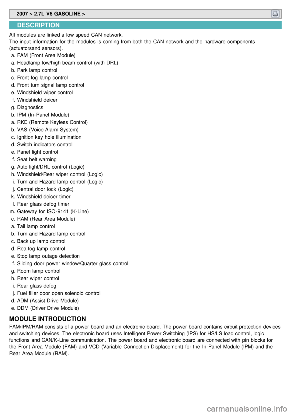
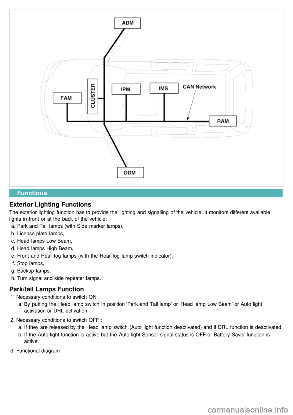
All modules are linked a low speed CAN network.
The input information for the modules is coming from both the CAN network and the hardware components
(actuatorsand sensors).
a. FAM (Front Area Module)
a. Headlamp low/high beam control (with DRL)
b. Park lamp control
c. Front fog lamp control
d. Front turn signal lamp control
e. Windshield wiper control
f. Windshield deicer
g. Diagnostics
b. IPM (In - Panel Module)
a. RKE (Remote Keyless Control)
b. VAS (Voice Alarm System)
c. Ignition key hole illumination
d. Switch indicators control
e. Panel light control
f. Seat belt warning
g. Auto light/DRL control (Logic)
h. Windshield/Rear wiper control (Logic)
i. Turn and Hazard lamp control (Logic)
j. Central door lock (Logic)
k. Windshield deicer timer
l. Rear glass defog timer
m. Gateway for ISO- 9141 (K- Line)
c. RAM (Rear Area Module)
a. Tail lamp control
b. Turn and Hazard lamp control
c. Back up lamp control
d. Rea fog lamp control
e. Stop lamp outage detection
f. Sliding door power window/Quarter glass control
g. Room lamp control
h. Rear wiper control
i. Rear glass defog
j. Fuel filler door open solenoid control
d. ADM (Assist Drive Module)
e. DDM (Driver Drive Module)
MODULE INTRODUCTION
FAM/IPM/RAM consists of a power board and an electronic board. The power board contains circuit protection devices
and switching devices. The electronic board uses Intelligent Power Switching (IPS) for HS/LS load control, logic
functions and CAN/K- Line communication. The power board and electronic board are connected with pin blocks for
the Front Area Module (FAM) and VCD (Variable Connection Displacement) for the In- Panel Module (IPM) and the
Rear Area Module (RAM).
Page 1212 of 1575
Functions
Exterior Lighting Functions
The exterior lighting function has to provide the lighting and signalling of the vehicle; it monitors different available
lights in front or at the back of the vehicle: a. Park and Tail lamps (with Side marker lamps),
b. License plate lamps,
c. Head lamps Low Beam,
d. Head lamps High Beam,
e. Front and Rear fog lamps (with the Rear fog lamp switch indicator),
f. Stop lamps,
g. Backup lamps,
h. Turn signal and side repeater lamps.
Park/tail Lamps Function
1.Necessary conditions to switch ON :
a. By putting the Head lamp switch in position 'Park and Tail lamp' or 'Head lamp Low Beam' or Auto light
activation or DRL activation
2. Necessary conditions to switch OFF :
a. If they are released by the Head lamp switch (Auto light function deactivated) and if DRL function is deactivated
b. If the Auto light function is active but the Auto light Sensor signal status is OFF or Battery Saver function is
active.
3. Functional diagram