sensor KIA CARNIVAL 2007 Workshop Manual
[x] Cancel search | Manufacturer: KIA, Model Year: 2007, Model line: CARNIVAL, Model: KIA CARNIVAL 2007Pages: 1575, PDF Size: 44.86 MB
Page 19 of 1575

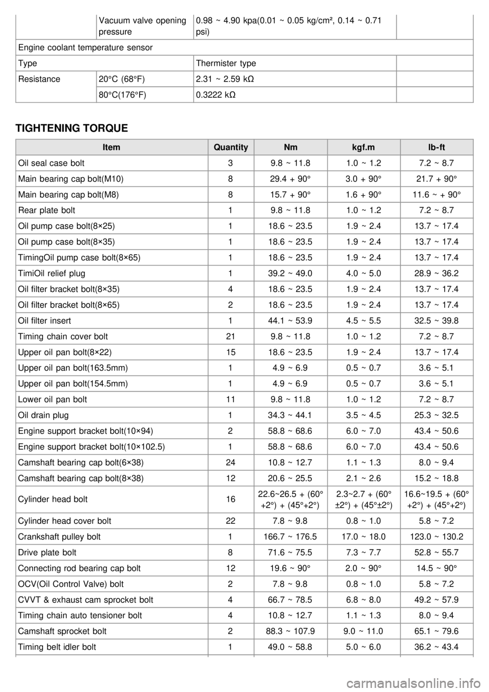
Vacuum valve opening
pressure0.98 ~ 4.90 kpa(0.01 ~ 0.05 kg/cm², 0.14 ~ 0.71
psi)
Engine coolant temperature sensor
Type Thermister type
Resistance 20°C (68°F) 2.31 ~ 2.59 kΩ
80°C(176°F) 0.3222 kΩ
TIGHTENING TORQUE
Item QuantityNmkgf.m lb- ft
Oil seal case bolt 39.8 ~ 11.8 1.0 ~ 1.27.2 ~ 8.7
Main bearing cap bolt(M10) 829.4 + 90° 3.0 + 90°21.7 + 90°
Main bearing cap bolt(M8) 815.7 + 90° 1.6 + 90°11.6 ~ + 90°
Rear plate bolt 19.8 ~ 11.8 1.0 ~ 1.27.2 ~ 8.7
Oil pump case bolt(8×25) 118.6 ~ 23.5 1.9 ~ 2.413.7 ~ 17.4
Oil pump case bolt(8×35) 118.6 ~ 23.5 1.9 ~ 2.413.7 ~ 17.4
TimingOil pump case bolt(8×65) 118.6 ~ 23.5 1.9 ~ 2.413.7 ~ 17.4
TimiOil relief plug 139.2 ~ 49.0 4.0 ~ 5.028.9 ~ 36.2
Oil filter bracket bolt(8×35) 418.6 ~ 23.5 1.9 ~ 2.413.7 ~ 17.4
Oil filter bracket bolt(8×65) 218.6 ~ 23.5 1.9 ~ 2.413.7 ~ 17.4
Oil filter insert 144.1 ~ 53.9 4.5 ~ 5.532.5 ~ 39.8
Timing chain cover bolt 219.8 ~ 11.8 1.0 ~ 1.27.2 ~ 8.7
Upper oil pan bolt(8×22) 1518.6 ~ 23.5 1.9 ~ 2.413.7 ~ 17.4
Upper oil pan bolt(163.5mm) 14.9 ~ 6.9 0.5 ~ 0.73.6 ~ 5.1
Upper oil pan bolt(154.5mm) 14.9 ~ 6.9 0.5 ~ 0.73.6 ~ 5.1
Lower oil pan bolt 119.8 ~ 11.8 1.0 ~ 1.27.2 ~ 8.7
Oil drain plug 134.3 ~ 44.1 3.5 ~ 4.525.3 ~ 32.5
Engine support bracket bolt(10×94) 258.8 ~ 68.6 6.0 ~ 7.043.4 ~ 50.6
Engine support bracket bolt(10×102.5) 158.8 ~ 68.6 6.0 ~ 7.043.4 ~ 50.6
Camshaft bearing cap bolt(6×38) 2410.8 ~ 12.7 1.1 ~ 1.38.0 ~ 9.4
Camshaft bearing cap bolt(8×38) 1220.6 ~ 25.5 2.1 ~ 2.615.2 ~ 18.8
Cylinder head bolt 1622.6~26.5 + (60°
+2°) + (45°+2°) 2.3~2.7 + (60°
±2°) + (45°±2°) 16.6~19.5 + (60°
+2°) + (45°+2°)
Cylinder head cover bolt 227.8 ~ 9.8 0.8 ~ 1.05.8 ~ 7.2
Crankshaft pulley bolt 1166.7 ~ 176.5 17.0 ~ 18.0123.0 ~ 130.2
Drive plate bolt 871.6 ~ 75.5 7.3 ~ 7.752.8 ~ 55.7
Connecting rod bearing cap bolt 1219.6 ~ 90° 2.0 ~ 90°14.5 ~ 90°
OCV(Oil Control Valve) bolt 27.8 ~ 9.8 0.8 ~ 1.05.8 ~ 7.2
CVVT & exhaust cam sprocket bolt 466.7 ~ 78.5 6.8 ~ 8.049.2 ~ 57.9
Timing chain auto tensioner bolt 410.8 ~ 12.7 1.1 ~ 1.38.0 ~ 9.4
Camshaft sprocket bolt 288.3 ~ 107.9 9.0 ~ 11.065.1 ~ 79.6
Timing belt idler bolt 149.0 ~ 58.8 5.0 ~ 6.036.2 ~ 43.4
Page 36 of 1575

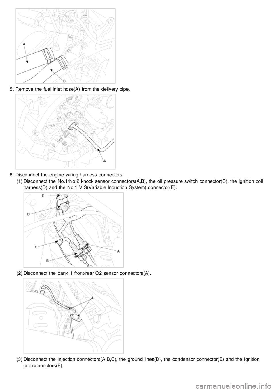
5.Remove the fuel inlet hose(A) from the delivery pipe.
6.Disconnect the engine wiring harness connectors.
(1) Disconnect the No.1/No.2 knock sensor connectors(A,B), the oil pressure switch connector(C), the ignition coil
harness(D) and the No.1 VIS(Variable Induction System) connector(E).
(2)Disconnect the bank 1 front/rear O2 sensor connectors(A).
(3)Disconnect the injection connectors(A,B,C), the ground lines(D), the condensor connector(E) and the Ignition
coil connectors(F).
Page 37 of 1575

(4)Disconnect the injection harness connector(A), the No.2 VIS(Variable Induction System) connector(B), the
No.1/No.2 OCV(Oil Control Valve) connectors(C,D) and the OTS(Oil Temperature Sensor) connector(E).
(5)Disconnect the MAPS(Manifold Absolute Pressure Sensor) connector(A), the ETC(Electronic Throttle Control)
connector(B) and the PCSV(Purge Control Solenoid Valve) connector(C).
(6)Disconnect the generator connector(A) and the air conditioning compressor connector(B).
Page 38 of 1575

(7)Disconnect the bank 2 CMP sensor connector(A) and the ECT(Engine Coolant Temperature) sensor
connector(B).
(8)Disconnect the bank 2 front/rear O2 sensor connectors(A,B) and the CKP sensor connector(C).
(9)Disconnect the bank 1 CMP sensor connector(A).
7.Remove the PCV(Pulge Control Valve) hose(A).
Page 41 of 1575

23.Remove the CKP sensor connector bracket(A).
24.Remove the cylinder head assembly.
(1) Remove the bolts in 2~3 steps as following orders.
If the bolts are not removed as the order, the deformation of the head assembly can be occurred.
(2) Put the cylinder head assembly on a wooden block after removal from the cylinder block.
Ensure that the surface between the cylinder head and the block is not damaged.
REPLACEMENT
Valve guide
1. Using the SST(09221- 3F100A), remove the valve guide from the downside of the cylinder head assembly.
Page 46 of 1575

7.Using the SST(09214- 21000), install the camshaft oil seal.
a.Befor installing, apply engine oil.
b. The camshaft cap surface should adhere to the cylinder head assembly.
c. Do not press an eccentric load.
8. Install the CKP sensor connector bracket(A).
9.Install the bank 1 timing belt rear cover(A).
10. Install the bank 2 timing belt rear cover(A).
Page 48 of 1575

a.Do not start engine for thirty minites after assembling the cylinder head cover.
b. Do not reuse the cylinder head cover gasket.
14. Install the water temp. control assembly.
15. Install the intake manifold assembly.
16. Install the exhaust mainfold assembly.
17. Install the power steering pump.(Refer to 'ST' group).
18. Install the drive belt(A).
19.Install the heater hose.
20. Connect the brake vaccume hose(A).
21.Install the PCV(Pulge Control Valve) hose(A).
22.Connect the engine wiring harness connectors.
(1) Connect the bank 1 CMP sensor connector(A).
Page 49 of 1575

(2)Connect the bank 2 front/rear O2 sensor connectors(A,B) and the CKP sensor connector(C).
(3)Connect the bank 2 CMP sensor connector(A) and the WTS(Water Temperature Sensor) connector(B).
(4)Connect the generator connector(A) and the air conditioning compressor connector(B).
(5)Connect the MAPS(Manifold Absolute Pressure Sensor) connector(A), the ETC(Electronic Throttle Control)
connector(B) and the PCSV(Purge Control Solenoid Valve) connector(C).
Page 50 of 1575

(6)Connect the injection harness connector(A), the No.2 VIS(Variable Induction System) connector(B), the
No.1/No.2 OCV(Oil Control Valve) connectors(C,D) and the OTS(Oil Temperature Sensor) connector(E).
(7)Connect the injection connectors(A,B,C), the ground lines(D), the condensor connector(E) and the Ignition coil
connectors(F).
(8)Connect the bank 1 front/rear O2 sensor connectors(A).
Page 51 of 1575

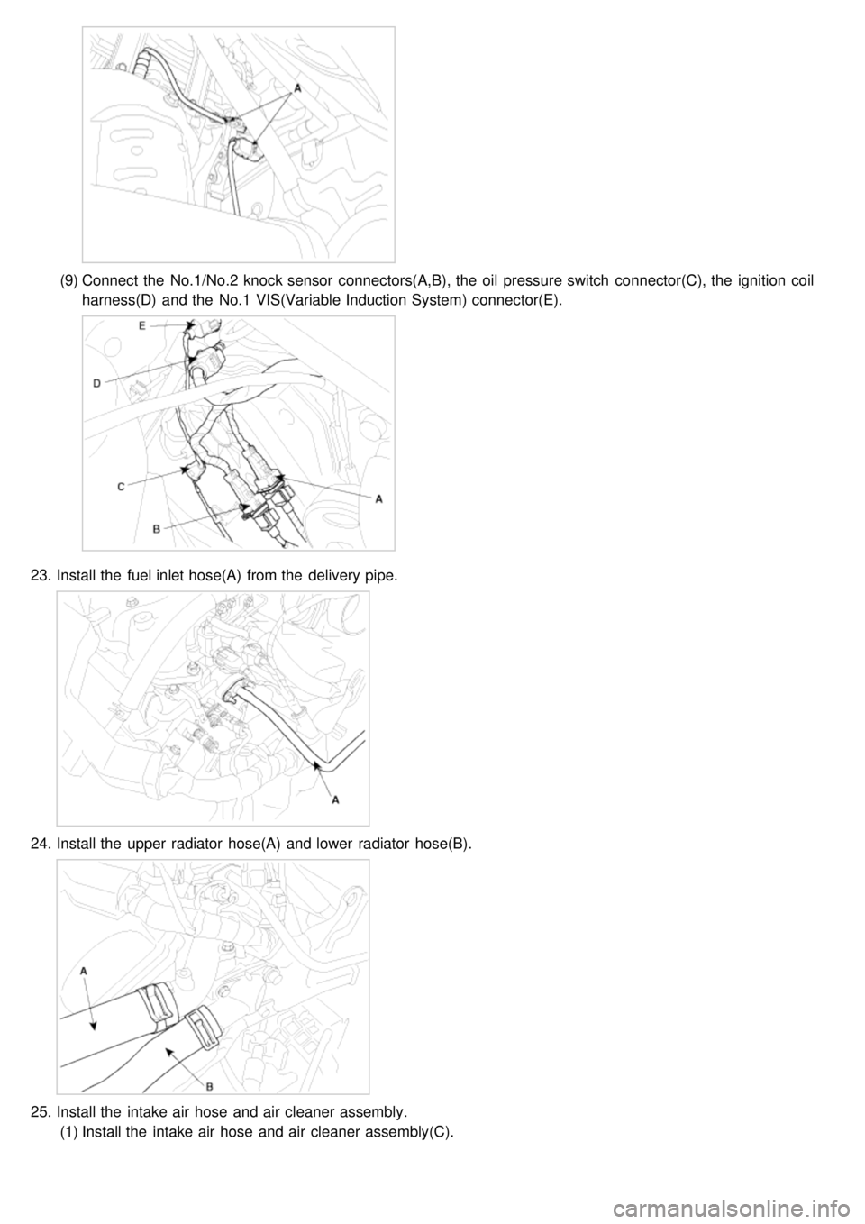
(9)Connect the No.1/No.2 knock sensor connectors(A,B), the oil pressure switch connector(C), the ignition coil
harness(D) and the No.1 VIS(Variable Induction System) connector(E).
23. Install the fuel inlet hose(A) from the delivery pipe.
24.Install the upper radiator hose(A) and lower radiator hose(B).
25.Install the intake air hose and air cleaner assembly.
(1) Install the intake air hose and air cleaner assembly(C).