transmission KIA CARNIVAL 2007 Workshop Manual
[x] Cancel search | Manufacturer: KIA, Model Year: 2007, Model line: CARNIVAL, Model: KIA CARNIVAL 2007Pages: 1575, PDF Size: 44.86 MB
Page 2 of 1575
2007 > 2.7L V6 GASOLINE >
IDENTIFICATION NUMBER DESCRIPTION
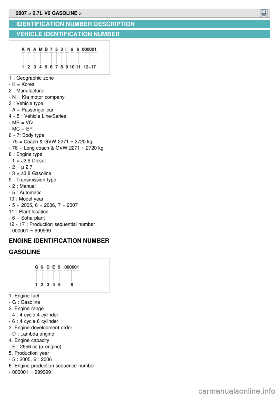
VEHICLE IDENTIFICATION NUMBER
1 : Geographic zone
- K = Korea
2 : Manufacturer
- N = Kia motor company
3 : Vehicle type
- A = Passenger car
4 - 5 : Vehicle Line/Series
- MB = VQ
- MC = EP
6 - 7: Body type
- 75 = Coach & GVW 2271 ~ 2720 kg
- 76 = Long coach & GVW 2271 ~ 2720 kg
8 : Engine type
- 1 = J2.9 Diesel
- 2 = µ 2.7
- 3 = λ3.8 Gasoline
9 : Transmission type
- 2 : Manual
- 5 : Automatic
10 : Model year
- 5 = 2005, 6 = 2006, 7 = 2007
11 : Plant location
- 6 = Soha plant
12 - 17 : Production sequential number
- 000001 ~ 999999
ENGINE IDENTIFICATION NUMBER
GASOLINE
1. Engine fuel
- G : Gasoline
2. Engine range
- 4 : 4 cycle 4 cylinder
- 6 : 4 cycle 6 cylinder
3. Engine development order
- D : Lambda engine
4. Engine capacity
- E : 2656 cc (µ- engine)
5. Production year
- 5 : 2005, 6 : 2006
6. Engine production sequence number
- 000001 ~ 999999
Page 3 of 1575
TRANSMISSION IDENTIFICATION NUMBER
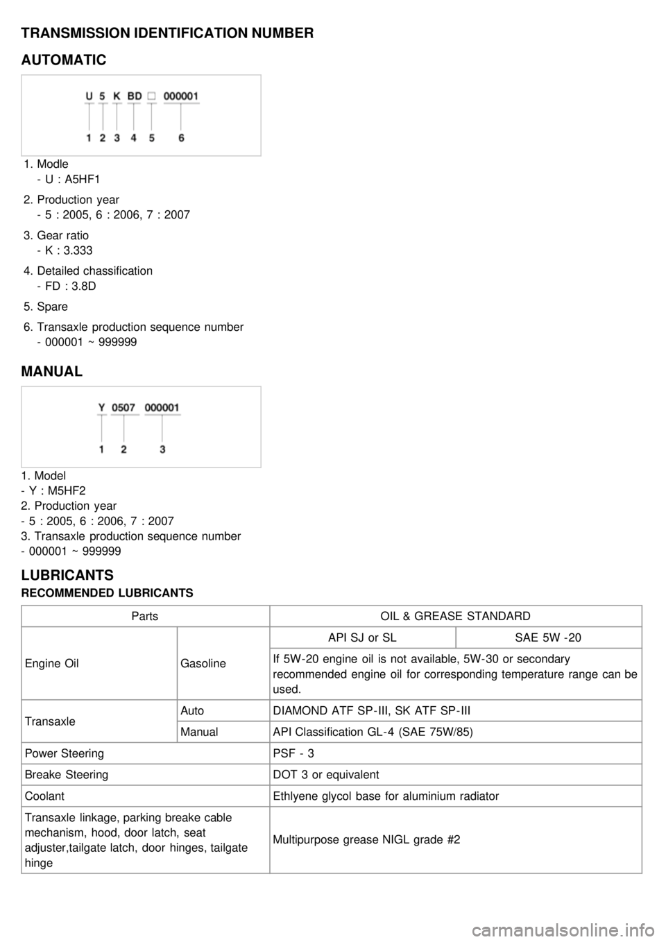
AUTOMATIC
1.Modle
- U : A5HF1
2. Production year
- 5 : 2005, 6 : 2006, 7 : 2007
3. Gear ratio
- K : 3.333
4. Detailed chassification
- FD : 3.8D
5. Spare
6. Transaxle production sequence number
- 000001 ~ 999999
MANUAL
1. Model
- Y : M5HF2
2. Production year
- 5 : 2005, 6 : 2006, 7 : 2007
3. Transaxle production sequence number
- 000001 ~ 999999
LUBRICANTS
RECOMMENDED LUBRICANTS
Parts OIL & GREASE STANDARD
Engine Oil GasolineAPI SJ or SL
SAE 5W - 20
If 5W- 20 engine oil is not available, 5W- 30 or secondary
recommended engine oil for corresponding temperature range can be
used.
Transaxle Auto
DIAMOND ATF SP - III, SK ATF SP - III
Manual API Classification GL - 4 (SAE 75W/85)
Power Steering PSF - 3
Breake Steering DOT 3 or equivalent
Coolant Ethlyene glycol base for aluminium radiator
Transaxle linkage, parking breake cable
mechanism, hood, door latch, seat
adjuster,tailgate latch, door hinges, tailgate
hinge Multipurpose grease NIGL grade #2
Page 329 of 1575
LUBRICANT
ItemSpecified lubricant Quantity
Transmission oil Diamond ATF SP - III8.5ℓ(9.0 Us qt, 7.5Imp.qt)
SEALANT Item Specified Sealant
Rear cover
Torque converter housing
Valve body cover Three Bond - TB 1281B or LOCTITE - FMD - 546
Transmission case side cover Three Bond - TB 1389 or LOCTITE - 518
Side cover Three Bond - TB 1389 or LOCTITE - 518/587
Page 337 of 1575
2007 > 2.7L V6 GASOLINE >
Hydraulic Control System
DESCRIPTION
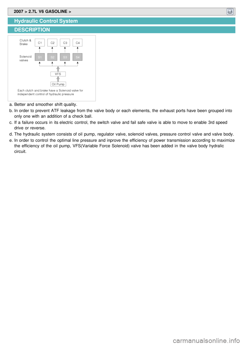
a.Better and smoother shift quality.
b. In order to prevent ATF leakage from the valve body or each elements, the exhaust ports have been grouped into
only one with an addition of a check ball.
c. If a failure occurs in its electric control, the switch valve and fail safe valve is able to move to enable 3rd speed
drive or reverse.
d. The hydraulic system consists of oil pump, regulator valve, solenoid valves, pressure control valve and valve body.
e. In order to control the optimal line pressure and inprove the efficiency of power transmission according to maximize
the efficiency of the oil pump, VFS(Variable Force Solenoid) valve has been added in the valve body hydralic
circuit.
Page 348 of 1575

2007 > 2.7L V6 GASOLINE >
Description
The automatic transmission is a combination of 3 - element 2 - phase 1 - stage torque converter and double shaft
electrocally - controlled unit which provides 4 speeds forward and 1 reverse. To improve the efficiency of power
transmission, the line pressure control was changed applying “Variable Force Solenoid (VFS) valve” on this model.
However, adopting VFS on this model, the line pressure is variably changed according to TPS and the vehicle speed,
this will enable more improved efficiency of power transmission and fuel consumption.
Characteristics
Some of the characteristics include:
▶Different power transfer
▶Different component layout
▶New shift logic(HIVEC) to improve shift feeling
▶Position of Valve Body
▶Variable shift pattern
▶Communication protocol and method
▶Step gate type shift lever.
Item Details
Weight Reduction 1. Aluminum oil pump
a. 2.3kg Approx
2. Pressed parts a. Retainer and hub of brakes and clutches
b. Carrier of planetary gear set
Better shift quality 1. Independent control of clutches and brakes enabled better control of
hydraulic pressure and skiped shifts (4 to 2, 3 to 1)
2. During N to D or N to R shift, feedback control adopted.
3. When starting from Creep condition, reduction of shock.(Creep condition is
controlled with 1st gear)
4. Solenoid valve frequency is increased for more accurate control. 35Hz to
61.3Hz except DCCSV that is 35Hz and VFS that is 600Hz.
5. HIVEC adoption for better shift feeling.
6. Variable shift pattern.
Increase in Power train efficiency 1. Fully Variable Line Pressure
2. VFS(Variable Force Solenoid)
- Manual shifting possible
- Step gate type shift lever
Page 351 of 1575
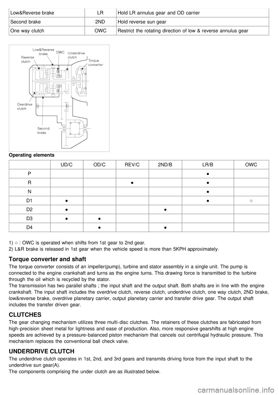
Low&Reverse brakeLRHold LR annulus gear and OD carrier
Second brake 2NDHold reverse sun gear
One way clutch OWCRestrict the rotating direction of low & reverse annulus gear
Operating elements
UD/COD/CREV/C 2ND/B LR/BOWC
P ●
R ●●
N ●
D1 ● ●○
D2 ● ●
D3 ●●
D4 ●●
1) ○ : OWC is operated when shifts from 1st gear to 2nd gear.
2) L&R brake is released in 1st gear when the vehicle speed is more than 5KPH approximately.
Torque converter and shaft
The torque converter consists of an impeller(pump), turbine and stator assembly in a single unit. The pump is
connected to the engine crankshaft and turns as the engine turns. This drawing force is transmitted to the turbine
through the oil which is recycled by the stator.
The transmission has two parallel shafts ; the input shaft and the output shaft. Both shafts are in line with the engine
crankshaft. The input shaft includes the overdrive clutch, reverse clutch, underdrive clutch, one way clutch, 2ND brake,
low&reverse brake, overdrive planetary carrier, output planetary carrier and transfer drive gear. The output shaft
includes the transfer driven gear.
CLUTCHES
The gear changing mechanism utilizes three multi- disc clutches. The retainers of these clutches are fabricated from
high- precision sheet metal for lightness and ease of production. Also, more responsive gearshifts at high engine
speeds are achieved by a pressure- balanced piston mechanism that cancels out centrifugal hydraulic pressure. This
mechanism replaces the conventional ball check valve.
UNDERDRIVE CLUTCH
The underdrive clutch operates in 1st, 2nd, and 3rd gears and transmits driving force from the input shaft to the
underdrive sun gear(A).
The components comprising the under clutch are as illustrated below.
Page 361 of 1575
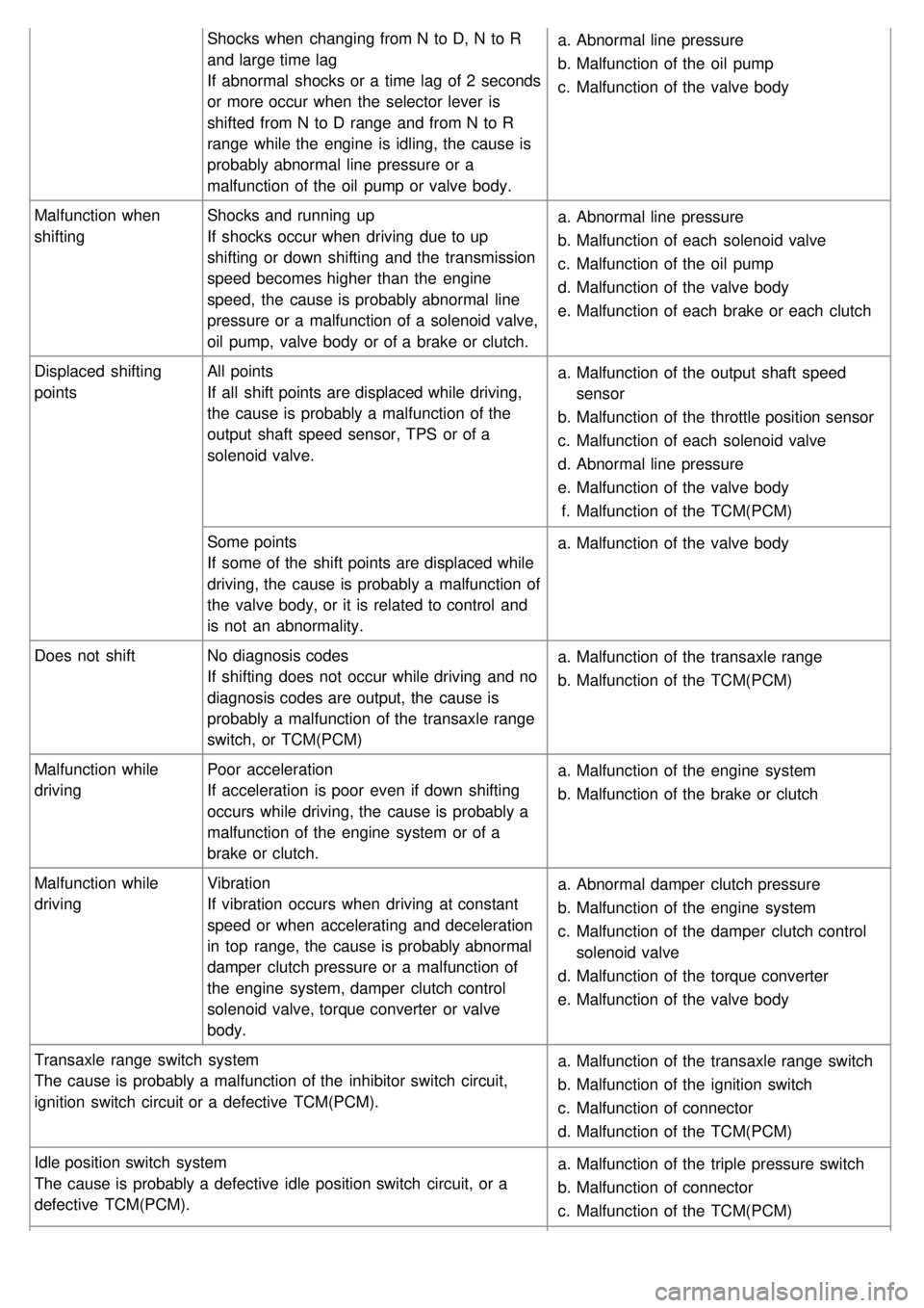
Shocks when changing from N to D, N to R
and large time lag
If abnormal shocks or a time lag of 2 seconds
or more occur when the selector lever is
shifted from N to D range and from N to R
range while the engine is idling, the cause is
probably abnormal line pressure or a
malfunction of the oil pump or valve body.a.
Abnormal line pressure
b. Malfunction of the oil pump
c. Malfunction of the valve body
Malfunction when
shifting Shocks and running up
If shocks occur when driving due to up
shifting or down shifting and the transmission
speed becomes higher than the engine
speed, the cause is probably abnormal line
pressure or a malfunction of a solenoid valve,
oil pump, valve body or of a brake or clutch. a.
Abnormal line pressure
b. Malfunction of each solenoid valve
c. Malfunction of the oil pump
d. Malfunction of the valve body
e. Malfunction of each brake or each clutch
Displaced shifting
points All points
If all shift points are displaced while driving,
the cause is probably a malfunction of the
output shaft speed sensor, TPS or of a
solenoid valve. a.
Malfunction of the output shaft speed
sensor
b. Malfunction of the throttle position sensor
c. Malfunction of each solenoid valve
d. Abnormal line pressure
e. Malfunction of the valve body
f. Malfunction of the TCM(PCM)
Some points
If some of the shift points are displaced while
driving, the cause is probably a malfunction of
the valve body, or it is related to control and
is not an abnormality. a.
Malfunction of the valve body
Does not shift No diagnosis codes
If shifting does not occur while driving and no
diagnosis codes are output, the cause is
probably a malfunction of the transaxle range
switch, or TCM(PCM) a.
Malfunction of the transaxle range
b. Malfunction of the TCM(PCM)
Malfunction while
driving Poor acceleration
If acceleration is poor even if down shifting
occurs while driving, the cause is probably a
malfunction of the engine system or of a
brake or clutch. a.
Malfunction of the engine system
b. Malfunction of the brake or clutch
Malfunction while
driving Vibration
If vibration occurs when driving at constant
speed or when accelerating and deceleration
in top range, the cause is probably abnormal
damper clutch pressure or a malfunction of
the engine system, damper clutch control
solenoid valve, torque converter or valve
body. a.
Abnormal damper clutch pressure
b. Malfunction of the engine system
c. Malfunction of the damper clutch control
solenoid valve
d. Malfunction of the torque converter
e. Malfunction of the valve body
Transaxle range switch system
The cause is probably a malfunction of the inhibitor switch circuit,
ignition switch circuit or a defective TCM(PCM). a.
Malfunction of the transaxle range switch
b. Malfunction of the ignition switch
c. Malfunction of connector
d. Malfunction of the TCM(PCM)
Idle position switch system
The cause is probably a defective idle position switch circuit, or a
defective TCM(PCM). a.
Malfunction of the triple pressure switch
b. Malfunction of connector
c. Malfunction of the TCM(PCM)
Page 362 of 1575

Triple pressure switch system
The cause is probably a defective dual pressure switch circuit or a
defective TCM(PCM).a.
Malfunction of the triple pressure switch
b. Malfunction of connector
c. Malfunction of A/C system
d. Malfunction of the TCM(PCM)
Vehicle speed sensor system
The cause is probably a defective vehicle speed sensor circuit or a
defective TCM(PCM). a.
Malfunction of the vehicle speed sensor
b. Malfunction of connector
c. Malfunction of the TCM(PCM)
DTC TROUBLESHOOTING INDEX
No. Code ItemMILRemark
1 P0707 TRANSAXLE RANGE SWITCH CIRCUIT LOW INPUT ON
2 P0708 TRANSAXLE RANGE SWITCH CIRCUIT HIGH INPUT ON
3 P0711 TRANSAXLE FLUID TEMPERATURE SENSOR RATIONALITY ON
4 P0712 TRANSAXLE FLUID TEMPERATURE SENSOR CIRCUIT LOW INPUT ON
5 P0713 TRANSAXLE FLUID TEMPERATURE SENSOR CIRCUIT HIGH INPUT ON
6 P0717 A/T INPUT SPEED SENSOR CIRCUIT - OPEN or SHORT(GND) ON
7 P0722 AT OUTPUT SPEED SENSOR CIRCUIT - OPEN or SHORT(GND) ON
8 P0731 GEAR 1 INCORRECT RATIO ON
9 P0732 GEAR 2 INCORRECT RATIO ON
10 P0733 GEAR 3 INCORRECT RATIO ON
11 P0734 GEAR 4 INCORRECT RATIO ON
12 P0741 TORQUE CONVERTER CLUTCH STUCK OFF ON
13 P0742 TORQUE CONVERTER CLUTCH STUCK ON ON
14 P0743 TORQUE CONVERTER CLUTCH CONTROL SOLENOID VALVE - OPEN or
SHORT(GND) ON
15 P0748 VFS SOLENOID OFF
16 P0750 LOW and REVERSE SOLENOID VALVE CIRCUIT - OPEN or SHORT(GND) ON
17 P0755 UNDER DRIVE SOLENOID VALVE CIRCUIT - OPEN or SHORT(GND) ON
18 P0760 SECOND SOLENOID VALVE CIRCUIT - OPEN or SHORT(GND) ON
19 P0765 OVERDRIVE SOLENOID VALVE CIRCUIT - OPEN or SHORT(GND) ON
20 P0885 A/T CONTROL RELAY - OPEN or SHORT(GND) ON
21 P0890 TCM power Relay sense circuit low ON
22 P0891 TCM power Relay sense circuit High ON
Failsafe
Activation and deactivation of error failsafe is coordinated Error failsafe Management.
Once Error failsafe is activated, it will be kept until ignition key OFF.
In every new TCM start, TCM start with No Error failsafe and No Error present.
0. Mechanical Limp Home Mode
a. Switch off A/T relay
1. Electrical Limp Home Mode a. Keep 2nd / 3rd gear
2. Prohibit Intelligent Shift a. Fuzzy SAT(Siements Adaptive Transmission) shift pattern (Medium Driver, Sporty Driver) will not be used
Page 365 of 1575
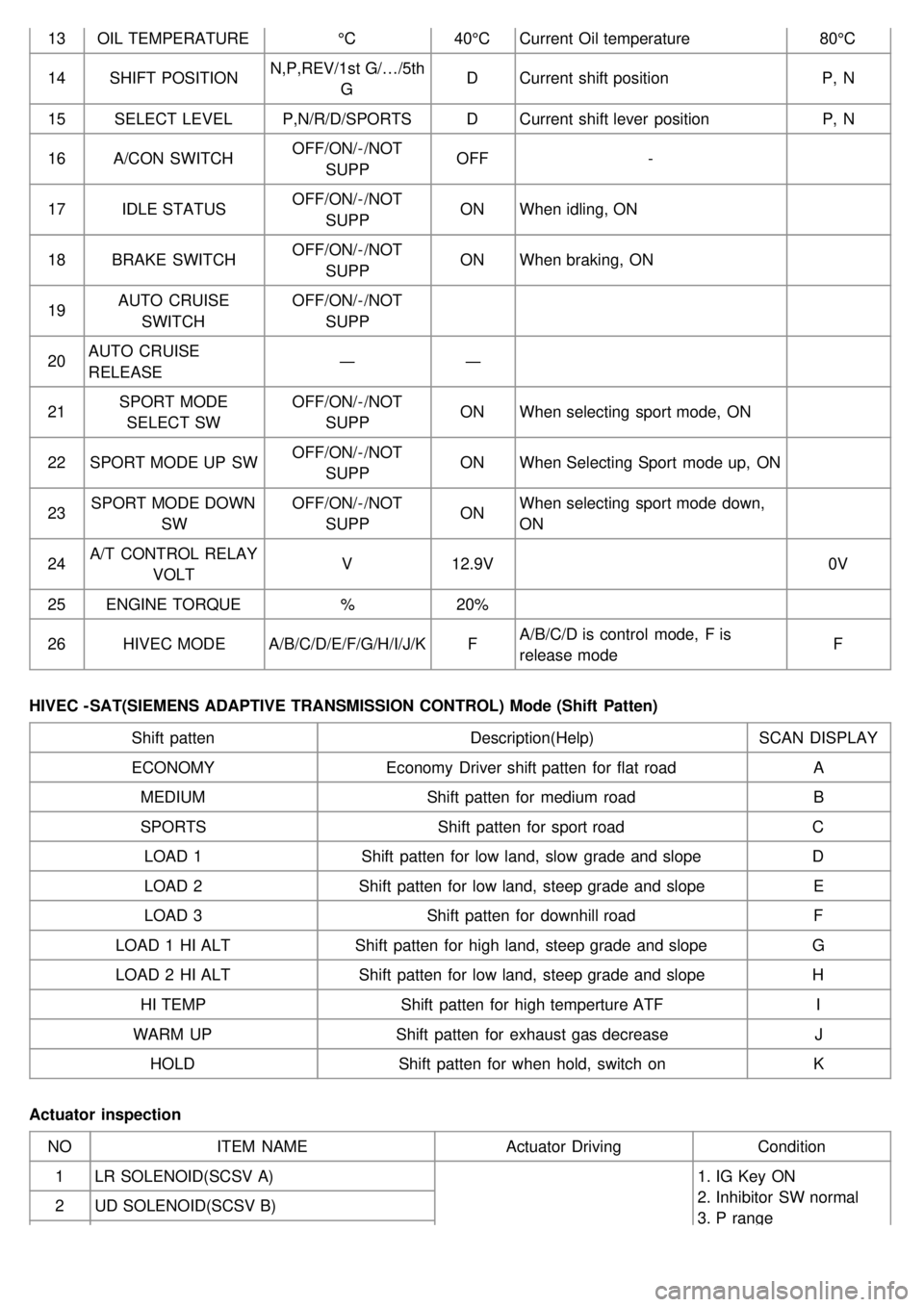
13OIL TEMPERATURE °C40°CCurrent Oil temperature 80°C
14 SHIFT POSITION N,P,REV/1st G/…/5th
G D
Current shift position P, N
15 SELECT LEVEL P,N/R/D/SPORTS DCurrent shift lever position P, N
16 A/CON SWITCH OFF/ON/- /NOT
SUPP OFF
-
17 IDLE STATUS OFF/ON/- /NOT
SUPP ON
When idling, ON
18 BRAKE SWITCH OFF/ON/- /NOT
SUPP ON
When braking, ON
19 AUTO CRUISE
SWITCH OFF/ON/- /NOT
SUPP
20 AUTO CRUISE
RELEASE ―
―
21 SPORT MODE
SELECT SW OFF/ON/- /NOT
SUPP ON
When selecting sport mode, ON
22 SPORT MODE UP SW OFF/ON/- /NOT
SUPP ON
When Selecting Sport mode up, ON
23 SPORT MODE DOWN
SW OFF/ON/- /NOT
SUPP ON
When selecting sport mode down,
ON
24 A/T CONTROL RELAY
VOLT V
12.9V 0V
25 ENGINE TORQUE %20%
26 HIVEC MODE A/B/C/D/E/F/G/H/I/J/K FA/B/C/D is control mode, F is
release mode F
HIVEC - SAT(SIEMENS ADAPTIVE TRANSMISSION CONTROL) Mode (Shift Patten) Shift patten Description(Help)SCAN DISPLAY
ECONOMY Economy Driver shift patten for flat road A
MEDIUM Shift patten for medium road B
SPORTS Shift patten for sport road C
LOAD 1 Shift patten for low land, slow grade and slope D
LOAD 2 Shift patten for low land, steep grade and slope E
LOAD 3 Shift patten for downhill road F
LOAD 1 HI ALT Shift patten for high land, steep grade and slope G
LOAD 2 HI ALT Shift patten for low land, steep grade and slope H
HI TEMP Shift patten for high temperture ATF I
WARM UP Shift patten for exhaust gas decrease J
HOLD Shift patten for when hold, switch on K
Actuator inspection NO ITEM NAME Actuator DrivingCondition
1 LR SOLENOID(SCSV A) 1. IG Key ON
2. Inhibitor SW normal
3. P range
2
UD SOLENOID(SCSV B)
Page 367 of 1575
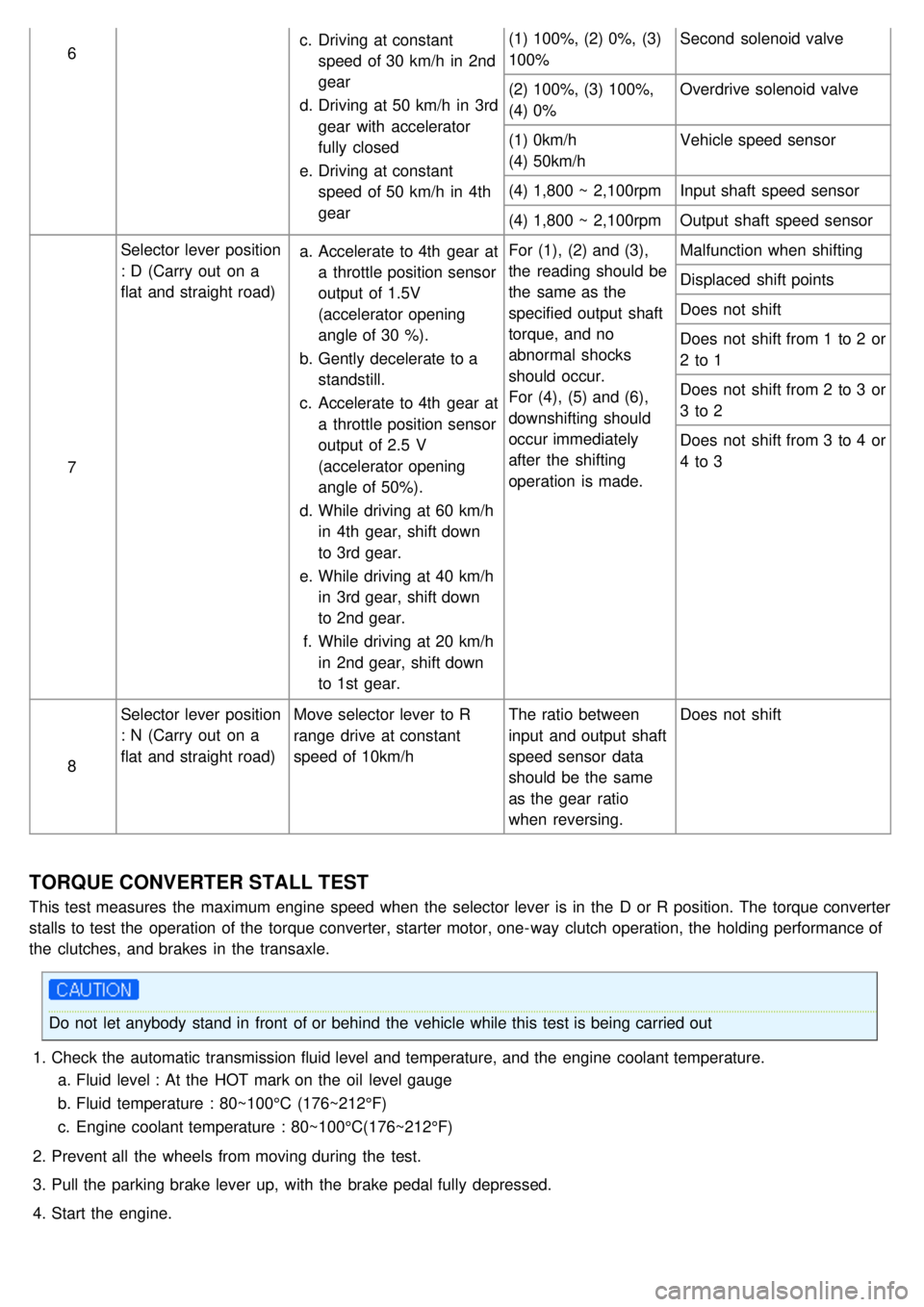
6c.
Driving at constant
speed of 30 km/h in 2nd
gear
d. Driving at 50 km/h in 3rd
gear with accelerator
fully closed
e. Driving at constant
speed of 50 km/h in 4th
gear (1) 100%, (2) 0%, (3)
100%
Second solenoid valve
(2) 100%, (3) 100%,
(4) 0% Overdrive solenoid valve
(1) 0km/h
(4) 50km/h Vehicle speed sensor
(4) 1,800 ~ 2,100rpm Input shaft speed sensor
(4) 1,800 ~ 2,100rpm Output shaft speed sensor
7 Selector lever position
: D (Carry out on a
flat and straight road)
a.
Accelerate to 4th gear at
a throttle position sensor
output of 1.5V
(accelerator opening
angle of 30 %).
b. Gently decelerate to a
standstill.
c. Accelerate to 4th gear at
a throttle position sensor
output of 2.5 V
(accelerator opening
angle of 50%).
d. While driving at 60 km/h
in 4th gear, shift down
to 3rd gear.
e. While driving at 40 km/h
in 3rd gear, shift down
to 2nd gear.
f. While driving at 20 km/h
in 2nd gear, shift down
to 1st gear. For (1), (2) and (3),
the reading should be
the same as the
specified output shaft
torque, and no
abnormal shocks
should occur.
For (4), (5) and (6),
downshifting should
occur immediately
after the shifting
operation is made.
Malfunction when shifting
Displaced shift points
Does not shift
Does not shift from 1 to 2 or
2 to 1
Does not shift from 2 to 3 or
3 to 2
Does not shift from 3 to 4 or
4 to 3
8 Selector lever position
: N (Carry out on a
flat and straight road)
Move selector lever to R
range drive at constant
speed of 10km/h The ratio between
input and output shaft
speed sensor data
should be the same
as the gear ratio
when reversing.Does not shift
TORQUE CONVERTER STALL TEST
This test measures the maximum engine speed when the selector lever is in the D or R position. The torque converter
stalls to test the operation of the torque converter, starter motor, one- way clutch operation, the holding performance of
the clutches, and brakes in the transaxle.
Do not let anybody stand in front of or behind the vehicle while this test is being carried out
1. Check the automatic transmission fluid level and temperature, and the engine coolant temperature.
a. Fluid level : At the HOT mark on the oil level gauge
b. Fluid temperature : 80~100°C (176~212°F)
c. Engine coolant temperature : 80~100°C(176~212°F)
2. Prevent all the wheels from moving during the test.
3. Pull the parking brake lever up, with the brake pedal fully depressed.
4. Start the engine.