turn signal KIA CARNIVAL 2007 Workshop Manual
[x] Cancel search | Manufacturer: KIA, Model Year: 2007, Model line: CARNIVAL, Model: KIA CARNIVAL 2007Pages: 1575, PDF Size: 44.86 MB
Page 239 of 1575
2007 > 2.7L V6 GASOLINE >
DESCRIPTION
1.Engine is hard to start or does not start at all.
2. Unstable idle.
3. Poor driveability
If any of the above conditions are noted, first perform a routine diagnosis that includes basic engine checks (ignition
system malfunction, incorrect engine adjustment, etc.). Then, inspect the Gasoline Engine Control system components
with the HI- SCAN (Pro).
a. Before removing or installing any part, read the diagnostic trouble codes and then disconnect the battery
negative ( - ) terminal.
b. Before disconnecting the cable from battery terminal, turn the ignition switch to OFF. Removal or connection
of the battery cable during engine operation or while the ignition switch is ON could cause damage to the
ECM.
c. The control harnesses between the ECM and heated oxygen sensor are shielded with the shielded ground
wires to the body in order to prevent the influence of ignition noises and radio interference. When the shielded
wire is faulty, the control harness must be replaced.
d. When checking the generator for the charging state, do not disconnect the battery '+' terminal to prevent the
ECM from damage due to the voltage.
e. When charging the battery with the external charger, disconnect the vehicle side battery terminals to prevent
damage to the ECM.
Malfunction Indicator Lamp (MIL)
Faults with the following items will illuminate the MIL.
a. Catalyst
b. Fuel system
c. Mass Air Flow Sensor (MAFS)
d. Intake Air Temperature Sensor (IATS)
e. Engine Coolant Temperature Sensor (ECTS)
f. Throttle Position Sensor (TPS)
g. Upstream Oxygen Sensor
h. Upstream Oxygen Sensor Heater
i. Downstream Oxygen Sensor
j. Downstream Oxygen Sensor Heater
k. Injector
l. Misfire
m. Crankshaft Position Sensor (CKPS)
n. Camshaft Position Sensor (CMPS)
o. Evaporative Emission Control System
p. Vehicle Speed Sensor (VSS)
q. Idle Speed Control Actuator (ISCA)
r. Power Supply
s. ECM/ PCM
t. MT/AT Encoding
u. Acceleration Sensor
v. MIL- on Request Signal
w. Power Stage
Refer to "INSPECTION CHART FOR DIAGNOSTIC TROUBLE CODES (DTC)" for more information.
Page 312 of 1575

MODE 1FORCED ENGINE
SHUTDOWN Engine stop algorithm procedure
a. Fatal PCM internal programming error
b. Faulty intake system or throttle body
MODE 2 FORCED IDLE &
POWER
MANAGEMENT Forced idle state controlled by
fuel quantity regulation and
ignition timing adjustment a.
ETC system can't control engine power
via throttle device
b. Disabled throttle control or broken throttle
position information
MODE 3 FORCED IDLE Forced idle state and no response
for accelerator activation a.
No information about the accelerator
position
a. Malfuctioning APS 1 and 2, faulty A/D
converter or internal controller
MODE 4 LIMIT
PERFORMANCE & POWER
MANAGEMENT Engine power is determined by
accelerator position and idle
power requirement (Limited
vehicle running)
a.
ETC system can't securely control engine
power
MODE 5 LIMIT
PERFORMANCE a.
Engine power varies with
accelerator position, but driver
perceives lack of engine
power.
b. MIL ON (Normal vehicle
running) a.
Not reliable accelerator position signal or
bad maximum power generation
a. Faulty APS, ignition voltage or internal
controller
MODE 6 NORMALNormal
COMPONENT INSPECTION
1.Connect a scantool on Diagnoisis Link Connector (DLC).
2. Start engine and check output voltages of TPS 1 and 2 at C.T and W.O.T.
Condition Output Voltage (V)
TPS 1 TPS 2
C.T 0.25 ~ 0.9V Min. 4.0V
W.O.T Min. 4.0V 0.25 ~ 0.9V
3. Turn ignition switch OFF and disconnect the scantool from the DLC.
4. Disconnect ETC module connector and measure resistance between ETC module terminals 4 and 1 (TPS 1).
5. Measure resistance between ETC module terminals 7 and 6 (TPS 2).
Specification: Refer to SPECIFICATION.
ETC MOTOR
1.Disconnect ETC module connector and measure resistance between ETC module terminals 5 and 8.
Page 338 of 1575
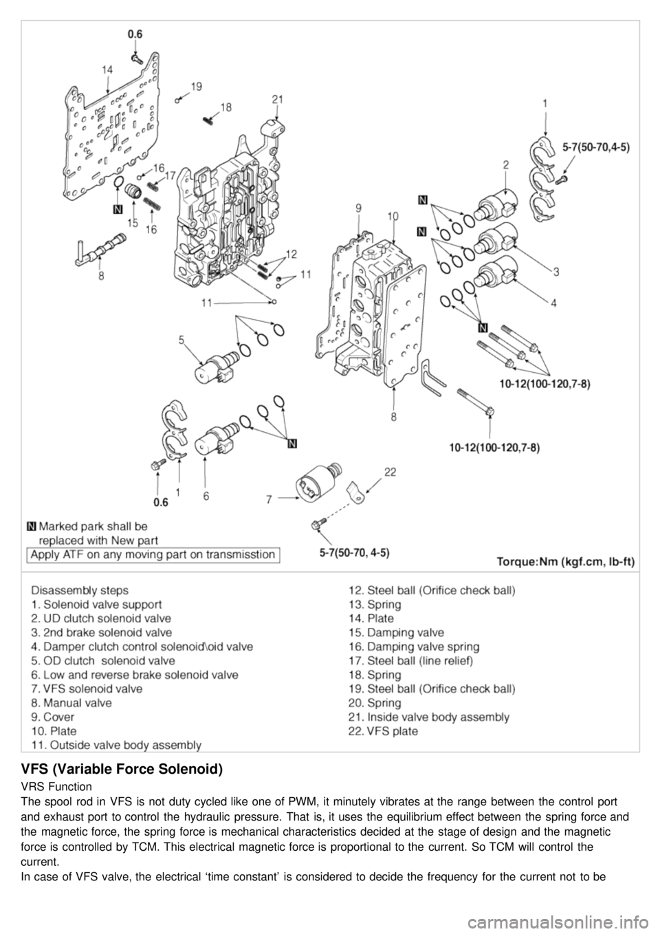
VFS (Variable Force Solenoid)
VRS Function
The spool rod in VFS is not duty cycled like one of PWM, it minutely vibrates at the range between the control port
and exhaust port to control the hydraulic pressure. That is, it uses the equilibrium effect between the spring force and
the magnetic force, the spring force is mechanical characteristics decided at the stage of design and the magnetic
force is controlled by TCM. This electrical magnetic force is proportional to the current. So TCM will control the
current.
In case of VFS valve, the electrical ‘time constant’ is considered to decide the frequency for the current not to be
fluctuated even though turns on or off the input signal. The electrical ‘time constant’ is much more fast than one of
Page 339 of 1575
fluctuated even though turns on or off the input signal. The electrical ‘time constant’ is much more fast than one of
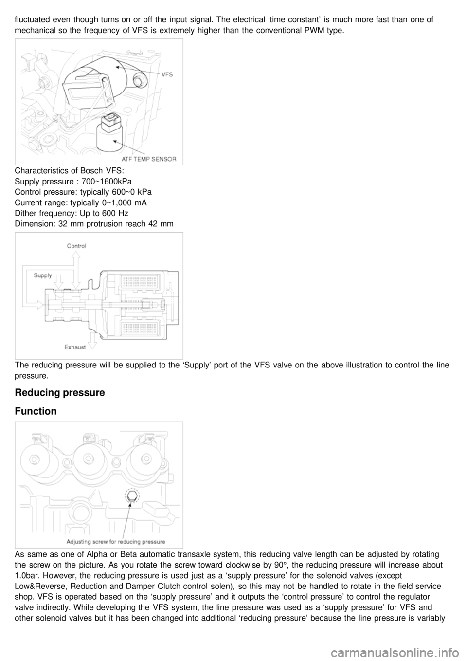
mechanical so the frequency of VFS is extremely higher than the conventional PWM type.
Characteristics of Bosch VFS:
Supply pressure : 700~1600kPa
Control pressure: typically 600~0 kPa
Current range: typically 0~1,000 mA
Dither frequency: Up to 600 Hz
Dimension: 32 mm protrusion reach 42 mm
The reducing pressure will be supplied to the ‘Supply’ port of the VFS valve on the above illustration to control the line
pressure.
Reducing pressure
Function
As same as one of Alpha or Beta automatic transaxle system, this reducing valve length can be adjusted by rotating
the screw on the picture. As you rotate the screw toward clockwise by 90°, the reducing pressure will increase about
1.0bar. However, the reducing pressure is used just as a ‘supply pressure’ for the solenoid valves (except
Low&Reverse, Reduction and Damper Clutch control solen), so this may not be handled to rotate in the field service
shop. VFS is operated based on the ‘supply pressure’ and it outputs the ‘control pressure’ to control the regulator
valve indirectly. While developing the VFS system, the line pressure was used as a ‘supply pressure’ for VFS and
other solenoid valves but it has been changed into additional ‘reducing pressure’ because the line pressure is variably
changed by VFS so the control pressure becomes unstable and some hydraulic pressure oscillation occurred. That is
Page 635 of 1575

2007 > 2.7L V6 GASOLINE >
TROUBLE SHOOTING
Symptom Probable cause Remedy
There is no change made in rack
stroke even though turning the VRS
switch ON or OFF. a.
VRS operating unit
b. VRS control module
c. VRS switch a.
Inspect the VRS operating unit.
b. Check Input/ output signal of the
VRS control module.
c. Inspect connection of the VRS
switch.
LED is not illuminated even though
turning the VRS switch ON. VRS switch a.
Inspect connection of the VRS
switch.
b. Check the LED for damage.
Inspection of the rack stroke
1.Is the rack stoke (the maximum steering angle) changed when pressing the VRS switch ?
▶ The VRS system is in normal condition.
▶ Go to step 2.
2. Measure the resistance of the VRS operating unit.
(1) Disconnect the VRS operating unit connector.
(2) Measure the resistance between the terminal No.1 and No.2.
Repeat the terminal No.3 and No.4.
Is the measured resistance within standard value ?
4 ~ 20 Ω → Normal condition (standard value)
1 Ω or below → Short
100 Ω or above → Open circuit
▶ Go to step 3.
▶ Repair or replace the power steering gear box.
3. Measure the output voltage of the VRS control module.
(1) Disconnect the VRS control module connector.
(2) Connect 9 ~ 15 V power between the terminal No.3 and No.4.
(3) Measure the output voltage (to DC motor) between the terminal No.5 ~ 8.
Is the voltage measured within standard value ?
Supplied power Measured output voltage
Page 702 of 1575
2007 > 2.7L V6 GASOLINE >
INSPECTION
1.Ignition "ON"
2. Using the scan tool.
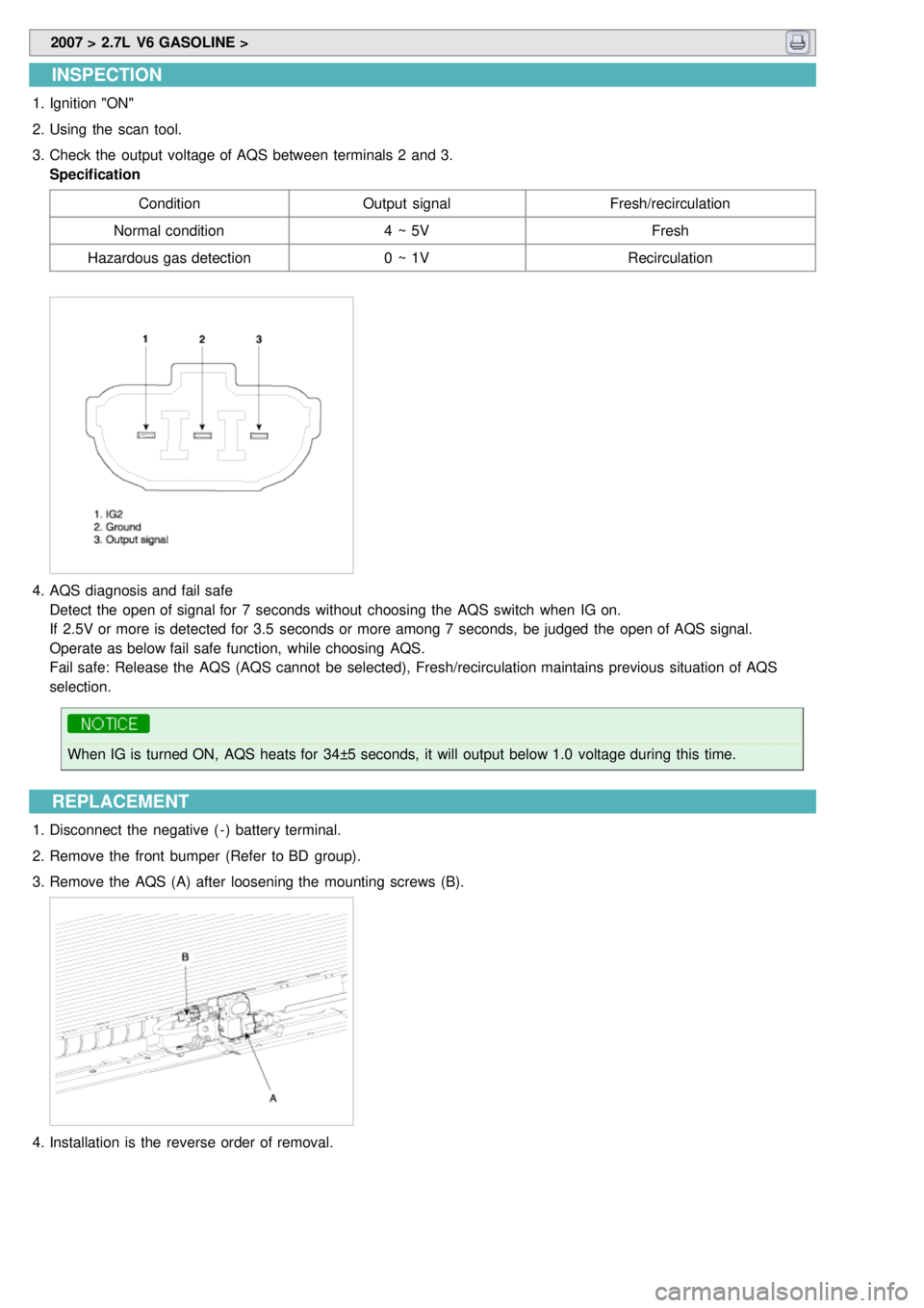
3. Check the output voltage of AQS between terminals 2 and 3.
Specification
Condition Output signal Fresh/recirculation
Normal condition 4 ~ 5VFresh
Hazardous gas detection 0 ~ 1VRecirculation
4.AQS diagnosis and fail safe
Detect the open of signal for 7 seconds without choosing the AQS switch when IG on.
If 2.5V or more is detected for 3.5 seconds or more among 7 seconds, be judged the open of AQS signal.
Operate as below fail safe function, while choosing AQS.
Fail safe: Release the AQS (AQS cannot be selected), Fresh/recirculation maintains previous situation of AQS
selection.
When IG is turned ON, AQS heats for 34±5 seconds, it will output below 1.0 voltage during this time.
REPLACEMENT
1.Disconnect the negative ( - ) battery terminal.
2. Remove the front bumper (Refer to BD group).
3. Remove the AQS (A) after loosening the mounting screws (B).
4.Installation is the reverse order of removal.
Page 795 of 1575

2007 > 2.7L V6 GASOLINE >
General
The supplemental restraint system (SRS) is designed to supplement the seat belt to help reduce the risk or severity of
injury to the driver and passenger by activating and deploying the driver, passenger, side airbag and belt pretensioner
in certain frontal or side collisions.
The SRS (Airbag) consists of : a driver side airbag module located in the center of the steering wheel, which contains
the folded cushion and an inflator unit ; a passenger side airbag module located in the passenger side crash pad
contains the folded cushion assembled with inflator unit ; side airbag modules located in the driver and passenger seat
contain the folded cushion and an inflator unit ; curtain airbag modules located inside of the headliner which contains
folded cushions and inflator units. The impact sensing function of the SRSCM is carried out by electronic
accelerometer that continuously measure the vehicle's acceleration and delivers a corresponding signal through
amplifying and filtering circuitry to the microprocessor.
SRSCM (SRS Control Module)
SRSCM will detect front impact with front impact sensor, and side impact with side impact sensor, and determine
airbag module deployment.
1. DC/DC converter: DC/DC converter in power supply unit includes up/down transformer converter, and provide
ignition voltage for 2 front airbag ignition circuits and the internal operation voltage of the SRSCM. If the internal
operation voltage is below critical value setting, it will perform resetting.
2. Safety sensor: Safety sensor is located in airbag ignition circuit. Safety sensor will operate airbag circuit at any
deployment condition and release airbag circuit safely at normal driving condition. Safety sensor is a double contact
electro - mechanical switch that will close detecting deceleration above certain criteria.
3. Back up power supply: SRSCM has separate back up power supply, that will supply deployment energy instantly in
low voltage condition or upon power failure by front crash.
4. Self diagnosis: SRSCM will constantly monitor current SRS operation status and detect system failure while vehicle
power supply is on, system failure may be checked with trouble codes using scan tool. (Hi- Scan)
5. Airbag warning lamp on: Upon detecting error, the module will transmit signal to SRSCM indicator lamp located at
cluster. MIL lamp will indicate driver SRS error. Upon ignition key on, SRS lamp will turn on for about six seconds.
6. Trouble code registration: Upon error occurrence in system, SRSCM will store DTC corresponding to the error.
DTC can be cleared only by Hi - Scan. However, if an internal fault code is logged or if a crash is recorded the fault
clearing should not happen.
7. Self diagnostic connector: Data stored in SRSCM memory will be output to Hi - Scan or other external output
devices through connector located below driver side crash pad.
8. Once airbag is deployed, SRSCM should not be used again but replaced.
9. SRSCM will determine whether passenger put on seat belt by the signal from built- in switch in seat belt buckle, and
deploy front seat airbag at each set crash speed.
10. Side airbag deployment will be determined by SRSCM that will detect satellite sensor impact signal upon side
crash, irrespective to seat belt condition.
Page 928 of 1575

2007 > 2.7L V6 GASOLINE >
DESCRIPTION
This specification applies to HCU(Hydraulic Control Unit) and ECU(Electronic Control Unit) of the HECU.(Hydraulic and
Electronic Control Unit)
This specification is for the wiring design and installation of ABS/TCS/ESC ECU.
This unit has the functions as follows.
a. Input of signal from Pressure sensor, Steering angle sensor, Yaw & Lateral G sensor, the wheel speed sensors
attached to each wheel.
b. Control of braking force / traction force/ yaw moment.
c. Failsafe function.
d. Self diagnosis function.
e. Interface with the external diagnosis tester.
Installation position : engine compartment a. Brake tube length from Master cylinder port to HECU inlet port should be max. 1m
b. The position should not be close to the engine block and not lower than the wheel.
OPERATION
The ECU shall be put into operation by switching on the operating voltage (IGN).
On completion of the initialization phase, the ECU shall be ready for operation.
In the operating condition, the ECU shall be ready, within the specified limits (voltage and temperature), to process the
signals offered by the various sensors and switches in accordance with the control algorithm defined by the software
and to control the hydraulic and electrical actuators.
Wheel Sensor signal processing
The ECU shall receive wheel speed signal from the four active wheel sensors.
The wheel signals are converted to voltage signal by the signal conditioning circuit after receiving current signal from
active wheel sensors and given as input to the MCU.
Solenoid Valve Control
When one side of the valve coil is connected to the positive voltage that is provided through the valve relay and the
other side is connected to the ground by the semiconductor circuit, the solenoid valve goes into operation.
The electrical function of the coils are always monitored by the valve test pulse under normal operation conditions.
Voltage limits
a.Overvoltage
When overvoltage is detected(above 16.8 V), the ECU switches off the valve relay and shuts down the system.
When voltage is returned to operating range, the system goes back to the normal condition after the initialization
phase.
b. Undervoltage
In the event of undervoltage(below 9.3 V), ABS control shall be inhibited and the warning lamp shall be turned on.
When voltage is returned to operating range, the warning lamp is switched off and ECU returns to normal operating
mode.
Pump Motor Checking
The ECU performs a pump motor test at a speed of 15km/h once after IGN is switched on.
Diagnostic Interface
Failures detected by the ECU are encoded on the ECU, stored in a EEPROM and read out by diagnostic equipment
when the ignition switch is turned on.
The diagnosis interface can also be used for testing the ECU during production of the ECU and for actuating the HCU
(Air - bleeding line or Roll and Brake Test line).
Warning Lamp module
Page 1211 of 1575
2007 > 2.7L V6 GASOLINE >
DESCRIPTION
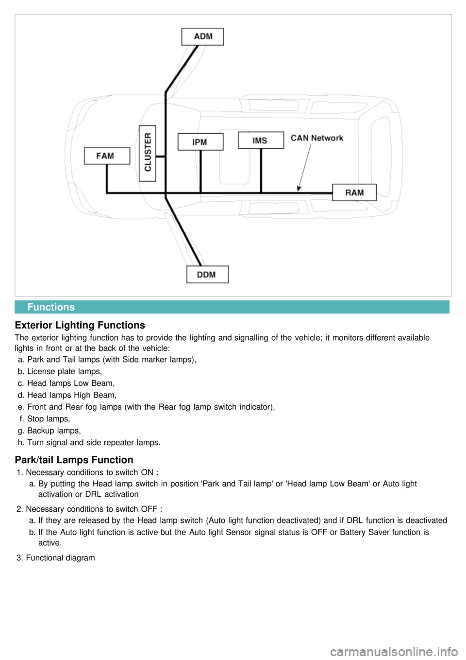
All modules are linked a low speed CAN network.
The input information for the modules is coming from both the CAN network and the hardware components
(actuatorsand sensors).
a. FAM (Front Area Module)
a. Headlamp low/high beam control (with DRL)
b. Park lamp control
c. Front fog lamp control
d. Front turn signal lamp control
e. Windshield wiper control
f. Windshield deicer
g. Diagnostics
b. IPM (In - Panel Module)
a. RKE (Remote Keyless Control)
b. VAS (Voice Alarm System)
c. Ignition key hole illumination
d. Switch indicators control
e. Panel light control
f. Seat belt warning
g. Auto light/DRL control (Logic)
h. Windshield/Rear wiper control (Logic)
i. Turn and Hazard lamp control (Logic)
j. Central door lock (Logic)
k. Windshield deicer timer
l. Rear glass defog timer
m. Gateway for ISO- 9141 (K- Line)
c. RAM (Rear Area Module)
a. Tail lamp control
b. Turn and Hazard lamp control
c. Back up lamp control
d. Rea fog lamp control
e. Stop lamp outage detection
f. Sliding door power window/Quarter glass control
g. Room lamp control
h. Rear wiper control
i. Rear glass defog
j. Fuel filler door open solenoid control
d. ADM (Assist Drive Module)
e. DDM (Driver Drive Module)
MODULE INTRODUCTION
FAM/IPM/RAM consists of a power board and an electronic board. The power board contains circuit protection devices
and switching devices. The electronic board uses Intelligent Power Switching (IPS) for HS/LS load control, logic
functions and CAN/K- Line communication. The power board and electronic board are connected with pin blocks for
the Front Area Module (FAM) and VCD (Variable Connection Displacement) for the In- Panel Module (IPM) and the
Rear Area Module (RAM).
Page 1212 of 1575
Functions
Exterior Lighting Functions
The exterior lighting function has to provide the lighting and signalling of the vehicle; it monitors different available
lights in front or at the back of the vehicle: a. Park and Tail lamps (with Side marker lamps),
b. License plate lamps,
c. Head lamps Low Beam,
d. Head lamps High Beam,
e. Front and Rear fog lamps (with the Rear fog lamp switch indicator),
f. Stop lamps,
g. Backup lamps,
h. Turn signal and side repeater lamps.
Park/tail Lamps Function
1.Necessary conditions to switch ON :
a. By putting the Head lamp switch in position 'Park and Tail lamp' or 'Head lamp Low Beam' or Auto light
activation or DRL activation
2. Necessary conditions to switch OFF :
a. If they are released by the Head lamp switch (Auto light function deactivated) and if DRL function is deactivated
b. If the Auto light function is active but the Auto light Sensor signal status is OFF or Battery Saver function is
active.
3. Functional diagram