symbols KIA CEED 2013 Owners Manual
[x] Cancel search | Manufacturer: KIA, Model Year: 2013, Model line: CEED, Model: KIA CEED 2013Pages: 1168, PDF Size: 48.01 MB
Page 9 of 1168
Introduction
6
1
* : if equipped ❈ For more detailed explanations, refer
to section 4, “Instrument cluster”.
Charging system warning light
Glow indicator (Diesel only)
Fuel filter warning light (Diesel only)Engine coolant temperature
warning light
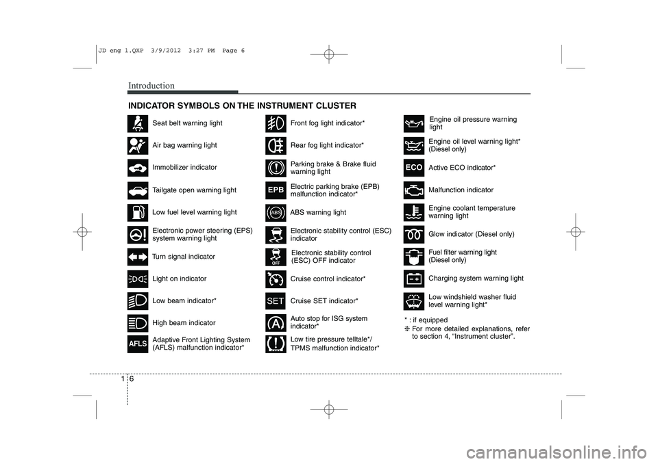
INDICATOR SYMBOLS ON THE INSTRUMENT CLUSTER
Seat belt warning light
High beam indicator
Light on indicator
Turn signal indicator
ABS warning light
Air bag warning light
Low fuel level warning light
Electronic stability control (ESC) indicator
Electronic stability control (ESC) OFF indicator
Immobilizer indicator
Low beam indicator*
Tailgate open warning light
Electronic power steering (EPS)
system warning light
Adaptive Front Lighting System (AFLS) malfunction indicator*
AFLS
Front fog light indicator*
Rear fog light indicator*
Parking brake & Brake fluid
warning light
Electric parking brake (EPB) malfunction indicator*
EPB
Active ECO
indicator*ECO
Auto stop for ISG system indicator*
Cruise control indicator*
Cruise SET indicator*
Engine oil pressure warning light
Malfunction indicator
Engine oil level warning light* (Diesel only)
Low tire pressure telltale*/ TPMS malfunction indicator* Low windshield washer fluid
level warning light*
JD eng 1.QXP 3/9/2012 3:27 PM Page 6
Page 52 of 1168
Safety system of your vehicle
36
3
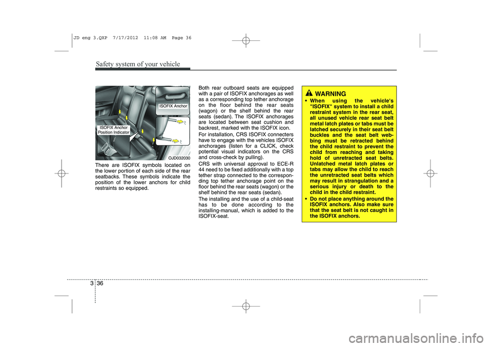
There are ISOFIX symbols located on
the lower portion of each side of the rear
seatbacks. These symbols indicate the
position of the lower anchors for child
restraints so equipped. Both rear outboard seats are equipped
with a pair of ISOFIX anchorages as well
as a corresponding top tether anchorageon the floor behind the rear seats
(wagon) or the shelf behind the rear
seats (sedan). The ISOFIX anchorages
are located between seat cushion and
backrest, marked with the ISOFIX icon.
For installation, CRS ISOFIX connecters
have to engage with the vehicles ISOFIX
anchorages (listen for a CLICK, checkpotential visual indicators on the CRS
and cross-check by pulling).
CRS with universal approval to ECE-R
44 need to be fixed additionally with a top
tether strap connected to the correspon-
ding top tether anchorage point on the
floor behind the rear seats (wagon) or theshelf behind the rear seats (sedan). The installing and the use of a child-seat has to be done according to the
installing-manual, which is added to theISOFIX-seat.
WARNING
When using the vehicle's "ISOFIX" system to install a child restraint system in the rear seat,
all unused vehicle rear seat belt
metal latch plates or tabs must be
latched securely in their seat belt
buckles and the seat belt web-
bing must be retracted behind
the child restraint to prevent the
child from reaching and takinghold of unretracted seat belts.
Unlatched metal latch plates or
tabs may allow the child to reach
the unretracted seat belts which
may result in strangulation and a
serious injury or death to the
child in the child restraint.
Do not place anything around the ISOFIX anchors. Also make surethat the seat belt is not caught in
the ISOFIX anchors.
OJD032030
ISOFIX Anchor
ISOFIX Anchor
Position Indicator
JD eng 3.QXP 7/17/2012 11:08 AM Page 36
Page 208 of 1168
4 129
Features of your vehicle
Mode selection
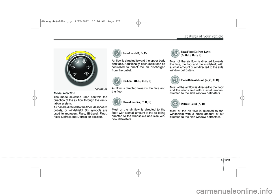
The mode selection knob controls the
direction of the air flow through the venti-lation system.
Air can be directed to the floor, dashboard
outlets, or windshield. Six symbols are
used to represent Face, Bi-Level, Floor,Floor-Defrost and Defrost air position.
Face-Level (B, D, F)
Air flow is directed toward the upper body
and face. Additionally, each outlet can becontrolled to direct the air dischargedfrom the outlet.
Bi-Level (B, D, C, E, F)
Air flow is directed towards the face and
the floor.
Floor-Level (A, C, D, E)
Most of the air flow is directed to the
floor, with a small amount of the air beingdirected to the windshield and side win-
dow defrosters.
Face/Floor/Defrost-Level (A, B, C, D, E, F)
Most of the air flow is directed towards
the face, the floor and the windshield witha small amount of air directed to the side
window defrosters.
Floor/Defrost-Level (A, C, E, D)
Most of the air flow is directed to the floorand the windshield with a small amount
directed to the side window defrosters.
Defrost-Level (A, D)
Most of the air flow is directed to thewindshield with a small amount of air
directed to the side window defrosters.
OJD042104
JD eng 4a(~168).qxp 7/17/2012 10:24 AM Page 129
Page 282 of 1168
4 203
Features of your vehicle
VOICE COMMAND (if equipped)
The voice recognition feature of this
product supports recognition of the
commands listed within this user’s
manual.
While using voice recognition, operating the steering remote control or the device
will terminate voice recognition and allow
you to manually operate desired func-
tions.
Position of the microphone is above the head of the driver’s seat.
Voice recognition may not function properly due to outside noise. The fol-
lowing conditions can affect the per-
formance of Voice Recognition:
- When the windows and sunroof are open
- When the heating/cooling system is on
- When passing a tunnel
- When driving on rugged and uneven roads
After downloading
Bluetooth®Wireless
Technology phone book, the system
requires some times to convert the
phone book into voice information.
During this time, voice recognition may
not operate properly. Upon inputting your phone book, spe-
cial symbols and numbers cannot be
recognized by voice. For example, “#
John Doe%&” will be recognized as“John Doe”. Starting Voice Command
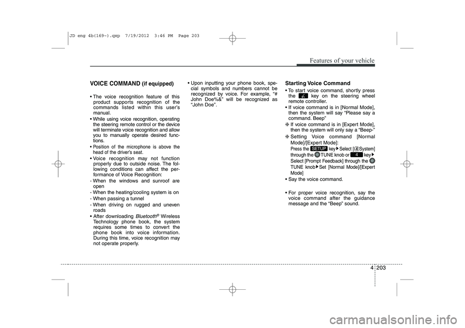
To start voice command, shortly press
the key on the steering wheel
remote controller.
If voice command is in [Normal Mode], then the system will say “Please say a
command. Beep”
❈ If voice command is in [Expert Mode],
then the system will only say a “Beep-”
❈ Setting Voice command [Normal
Mode]/[Expert Mode]:
Press the key Select [ System]
through the TUNE knob or key
Select [Prompt Feedback] through the
TUNE knob Set [Normal Mode]/[ExpertMode]
Say the voice command.
For proper voice recognition, say the
voice command after the guidance
message and the “Beep” sound.
4
SETUP
JD eng 4b(169~).qxp 7/19/2012 3:46 PM Page 203
Page 577 of 1168

Index
6
I
Gauge (Normal vision)
Engine temperature gauge. . . . . . . . . . . . . . . . . . . . 4-54
Fuel gauge . . . . . . . . . . . . . . . . . . . . . . . . . . . . . . . . . 4-48
Gauge (Super vision) Engine temperature gauge. . . . . . . . . . . . . . . . . . . . 4-67
Fuel gauge . . . . . . . . . . . . . . . . . . . . . . . . . . . . . . . . . 4-61
Glove box . . . . . . . . . . . . . . . . . . . . . . . . . . . . . . . . . . 4-152
Glove box lamp . . . . . . . . . . . . . . . . . . . . . . . . . . . . . 4-124
Hazard warning flasher . . . . . . . . . . . . . . . . . . . . . . 4-109
Hazardous driving conditions . . . . . . . . . . . . . . . . . . 5-64
Headlamp delay function . . . . . . . . . . . . . . . . . . . . . 4-110
Headlight (Headlamp) welcome function . . . . . . . . 4-110
Headlight bulb replacement. . . . . . . . . . . . . . . . . . . . 7-82
Headlight leveling device . . . . . . . . . . . . . . . . . . . . . 4-116
Headlight position . . . . . . . . . . . . . . . . . . . . . . . . . . . 4-112
Headlight washer . . . . . . . . . . . . . . . . . . . . . . . . . . . 4-121
Headrest(front) . . . . . . . . . . . . . . . . . . . . . . . . . . . . . . 3-10
Headrest(rear) . . . . . . . . . . . . . . . . . . . . . . . . . . . . . . . 3-13
Heated steering wheel. . . . . . . . . . . . . . . . . . . . . . . . . 4-38
High - beam operation . . . . . . . . . . . . . . . . . . . . . . . 4-113
Hight adjustment (seat belt) . . . . . . . . . . . . . . . . . . . 3-21
Highway driving . . . . . . . . . . . . . . . . . . . . . . . . . . . . . 5-66 Hill-start assist control (HAC). . . . . . . . . . . . . . . . . . 5-48
Hood . . . . . . . . . . . . . . . . . . . . . . . . . . . . . . . . . . . . . . . 4-28
Horn . . . . . . . . . . . . . . . . . . . . . . . . . . . . . . . . . . . . . . . 4-39
How to use this manual . . . . . . . . . . . . . . . . . . . . . . . . 1-2
Icy road warning . . . . . . . . . . . . . . . . . . . . . . . . . . . . . 4-89
Indicator symbols on the instrument cluster . . . . . . . 1-6
Indicators and warnings . . . . . . . . . . . . . . . . . . . . . . 4-77
Inside rearview mirror . . . . . . . . . . . . . . . . . . . . . . . . 4-42Instrument cluster
LCD display information . . . . . . . . . . . . . . . . . . . . . 4-71
Warning and indicators . . . . . . . . . . . . . . . . . . . . . . 4-77
Instrument cluster (Normal vision). . . . . . . . . . . . . . 4-46
Automatic transaxle shift position indicator . . . . . 4-49
Double clutch transmission shift indicator . . . . . . 4-49
Fuel gauge . . . . . . . . . . . . . . . . . . . . . . . . . . . . . . . . . 4-48
Instrument panel illumination . . . . . . . . . . . . . . . . 4-47
Manual transaxle shift indicator. . . . . . . . . . . . . . . 4-48
Odometer . . . . . . . . . . . . . . . . . . . . . . . . . . . . . . . . . . 4-50
Speed limiter indicator. . . . . . . . . . . . . . . . . . . . . . . 4-50
Speedometer . . . . . . . . . . . . . . . . . . . . . . . . . . . . . . . 4-47
Tachometer . . . . . . . . . . . . . . . . . . . . . . . . . . . . . . . . 4-47
Trip computer . . . . . . . . . . . . . . . . . . . . . . . . . . . . . . 4-51
User Settings . . . . . . . . . . . . . . . . . . . . . . . . . . . . . . . 4-56
G
H
I
JD eng Index.qxp 7/21/2012 11:45 AM Page 6
Page 593 of 1168
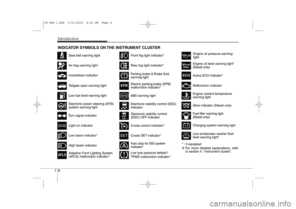
Introduction
6
1
* : if equipped ❈ For more detailed explanations, refer
to section 4, “Instrument cluster”.
Charging system warning light
Glow indicator (Diesel only)
Fuel filter warning light (Diesel only)Engine coolant temperature
warning light
INDICATOR SYMBOLS ON THE INSTRUMENT CLUSTER
Seat belt warning light
High beam indicator
Light on indicator
Turn signal indicator
ABS warning light
Air bag warning light
Low fuel level warning light
Electronic stability control (ESC) indicator
Electronic stability control (ESC) OFF indicator
Immobiliser indicator
Low beam indicator*
Tailgate open warning light
Electronic power steering (EPS)
system warning light
Adaptive Front Lighting System (AFLS) malfunction indicator*
AFLS
Front fog light indicator*
Rear fog light indicator*
Parking brake & Brake fluid
warning light
Electric parking brake (EPB) malfunction indicator*
EPB
Active ECO
indicator*ECO
Auto stop for ISG system indicator*
Cruise control indicator*
Cruise SET indicator*
Engine oil pressure warning light
Malfunction indicator
Engine oil level warning light* (Diesel only)
Low tyre pressure telltale*/ TPMS malfunction indicator* Low windscreen washer fluid
level warning light*
JD RHD 1.QXP 3/21/2012 4:55 PM Page 6
Page 636 of 1168
Safety system of your vehicle
36
3
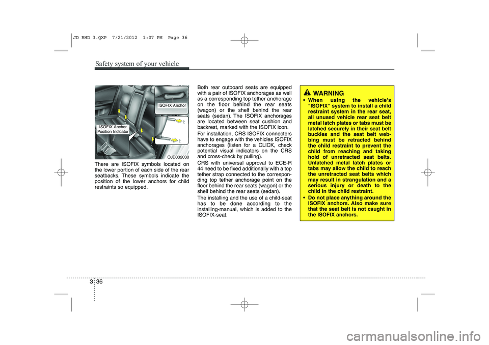
There are ISOFIX symbols located on
the lower portion of each side of the rear
seatbacks. These symbols indicate the
position of the lower anchors for child
restraints so equipped. Both rear outboard seats are equipped
with a pair of ISOFIX anchorages as well
as a corresponding top tether anchorageon the floor behind the rear seats
(wagon) or the shelf behind the rear
seats (sedan). The ISOFIX anchorages
are located between seat cushion and
backrest, marked with the ISOFIX icon.
For installation, CRS ISOFIX connecters
have to engage with the vehicles ISOFIX
anchorages (listen for a CLICK, checkpotential visual indicators on the CRS
and cross-check by pulling).
CRS with universal approval to ECE-R
44 need to be fixed additionally with a top
tether strap connected to the correspon-
ding top tether anchorage point on the
floor behind the rear seats (wagon) or theshelf behind the rear seats (sedan). The installing and the use of a child-seat has to be done according to the
installing-manual, which is added to theISOFIX-seat.
WARNING
When using the vehicle's "ISOFIX" system to install a child restraint system in the rear seat,
all unused vehicle rear seat belt
metal latch plates or tabs must be
latched securely in their seat belt
buckles and the seat belt web-
bing must be retracted behind
the child restraint to prevent the
child from reaching and takinghold of unretracted seat belts.
Unlatched metal latch plates or
tabs may allow the child to reach
the unretracted seat belts which
may result in strangulation and a
serious injury or death to the
child in the child restraint.
Do not place anything around the ISOFIX anchors. Also make surethat the seat belt is not caught in
the ISOFIX anchors.
OJD032030
ISOFIX Anchor
ISOFIX Anchor
Position Indicator
JD RHD 3.QXP 7/21/2012 1:07 PM Page 36
Page 792 of 1168
4 129
Features of your vehicle
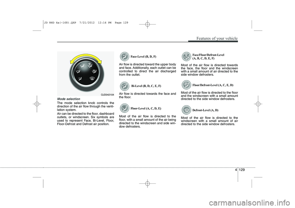
Mode selection
The mode selection knob controls the
direction of the air flow through the venti-lation system.
Air can be directed to the floor, dashboard
outlets, or windscreen. Six symbols are
used to represent Face, Bi-Level, Floor,Floor-Defrost and Defrost air position.
Face-Level (B, D, F)
Air flow is directed toward the upper body
and face. Additionally, each outlet can becontrolled to direct the air dischargedfrom the outlet.
Bi-Level (B, D, C, E, F)
Air flow is directed towards the face and
the floor.
Floor-Level (A, C, D, E)
Most of the air flow is directed to the
floor, with a small amount of the air beingdirected to the windscreen and side win-
dow defrosters.
Face/Floor/Defrost-Level (A, B, C, D, E, F)
Most of the air flow is directed towards
the face, the floor and the windscreenwith a small amount of air directed to the
side window defrosters.
Floor/Defrost-Level (A, C, E, D)
Most of the air flow is directed to the floorand the windscreen with a small amount
directed to the side window defrosters.
Defrost-Level (A, D)
Most of the air flow is directed to thewindscreen with a small amount of air
directed to the side window defrosters.
OJD042104
JD RHD 4a(~168).QXP 7/21/2012 12:14 PM Page 129
Page 866 of 1168
4 203
Features of your vehicle
VOICE COMMAND (if equipped)
The voice recognition feature of this
product supports recognition of the
commands listed within this user’s
manual.
Whilst using voice recognition, operating the steering remote control or the device
will terminate voice recognition and allow
you to manually operate desired func-
tions.
Position of the microphone is above the head of the driver’s seat.
Voice recognition may not function properly due to outside noise. The fol-
lowing conditions can affect the per-
formance of Voice Recognition:
- When the windows and sunroof are open
- When the heating/cooling system is on
- When passing a tunnel
- When driving on rugged and uneven roads
After downloading
Bluetooth®Wireless
Technology phone book, the system
requires some times to convert the
phone book into voice information.
During this time, voice recognition may
not operate properly. Upon inputting your phone book, spe-
cial symbols and numbers cannot be
recognized by voice. For example, “#
John Doe%&” will be recognized as“John Doe”. Starting Voice Command
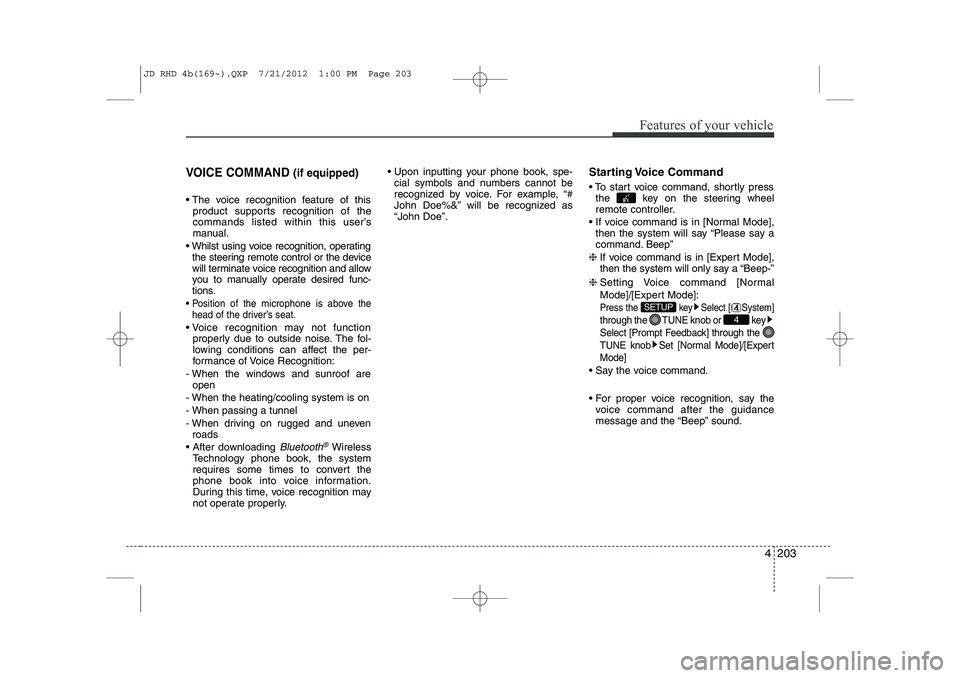
To start voice command, shortly press
the key on the steering wheel
remote controller.
If voice command is in [Normal Mode], then the system will say “Please say a
command. Beep”
❈ If voice command is in [Expert Mode],
then the system will only say a “Beep-”
❈ Setting Voice command [Normal
Mode]/[Expert Mode]:
Press the key Select [ System]
through the TUNE knob or key
Select [Prompt Feedback] through the
TUNE knob Set [Normal Mode]/[ExpertMode]
Say the voice command.
For proper voice recognition, say the
voice command after the guidance
message and the “Beep” sound.
4
SETUP
JD RHD 4b(169~).QXP 7/21/2012 1:00 PM Page 203
Page 1161 of 1168

Index
6
I
Fuse/relay panel description . . . . . . . . . . . . . . . . . . 7-67
Inner panel fuse . . . . . . . . . . . . . . . . . . . . . . . . . . . . 7-64
Main fuse . . . . . . . . . . . . . . . . . . . . . . . . . . . . . . . . . . 7-66
Multi fuse. . . . . . . . . . . . . . . . . . . . . . . . . . . . . . . . . . 7-66
Gauge (Normal vision) Engine temperature gauge. . . . . . . . . . . . . . . . . . . . 4-54
Fuel gauge . . . . . . . . . . . . . . . . . . . . . . . . . . . . . . . . . 4-48
Gauge (Super vision) Engine temperature gauge. . . . . . . . . . . . . . . . . . . . 4-67
Fuel gauge . . . . . . . . . . . . . . . . . . . . . . . . . . . . . . . . . 4-61
Glove box . . . . . . . . . . . . . . . . . . . . . . . . . . . . . . . . . . 4-152
Glove box lamp . . . . . . . . . . . . . . . . . . . . . . . . . . . . . 4-124
Hazard warning flasher . . . . . . . . . . . . . . . . . . . . . . 4-109
Hazardous driving conditions . . . . . . . . . . . . . . . . . . 5-64
Headlamp delay function . . . . . . . . . . . . . . . . . . . . . 4-110
Headlight (Headlamp) welcome function . . . . . . . . 4-110
Headlight bulb replacement. . . . . . . . . . . . . . . . . . . . 7-82
Headlight levelling device. . . . . . . . . . . . . . . . . . . . . 4-116
Headlight position . . . . . . . . . . . . . . . . . . . . . . . . . . . 4-112
Headlight washer . . . . . . . . . . . . . . . . . . . . . . . . . . . 4-121
Headrest(front) . . . . . . . . . . . . . . . . . . . . . . . . . . . . . . 3-10
Headrest(rear) . . . . . . . . . . . . . . . . . . . . . . . . . . . . . . . 3-13 Heated steering wheel. . . . . . . . . . . . . . . . . . . . . . . . . 4-38
High - beam operation . . . . . . . . . . . . . . . . . . . . . . . 4-113
Height adjustment (seat belt) . . . . . . . . . . . . . . . . . . 3-21
Highway driving . . . . . . . . . . . . . . . . . . . . . . . . . . . . . 5-66
Hill-start assist control (HAC). . . . . . . . . . . . . . . . . . 5-48
Horn . . . . . . . . . . . . . . . . . . . . . . . . . . . . . . . . . . . . . . . 4-39
How to use this manual . . . . . . . . . . . . . . . . . . . . . . . . 1-2
Icy road warning . . . . . . . . . . . . . . . . . . . . . . . . . . . . . 4-89
Indicator symbols on the instrument cluster . . . . . . . 1-6
Indicators and warnings . . . . . . . . . . . . . . . . . . . . . . 4-77
Inside rearview mirror . . . . . . . . . . . . . . . . . . . . . . . . 4-42Instrument cluster
LCD display information . . . . . . . . . . . . . . . . . . . . . 4-71
Warning and indicators . . . . . . . . . . . . . . . . . . . . . . 4-77
Instrument cluster (Normal vision). . . . . . . . . . . . . . 4-46 Automatic transaxle shift position indicator . . . . . 4-49
Double clutch transmission shift indicator . . . . . . 4-49
Fuel gauge . . . . . . . . . . . . . . . . . . . . . . . . . . . . . . . . . 4-48
Instrument panel illumination . . . . . . . . . . . . . . . . 4-47
Manual transaxle shift indicator. . . . . . . . . . . . . . . 4-48
Odometer . . . . . . . . . . . . . . . . . . . . . . . . . . . . . . . . . . 4-50
Speed limiter indicator. . . . . . . . . . . . . . . . . . . . . . . 4-50
Speedometer . . . . . . . . . . . . . . . . . . . . . . . . . . . . . . . 4-47
Tachometer . . . . . . . . . . . . . . . . . . . . . . . . . . . . . . . . 4-47
G
H
I
JD RHD Index.QXP 7/21/2012 1:10 PM Page 6