clock KIA CEED 2014 Owner's Manual
[x] Cancel search | Manufacturer: KIA, Model Year: 2014, Model line: CEED, Model: KIA CEED 2014Pages: 1206, PDF Size: 50.15 MB
Page 566 of 1206
Maintenance
108
7
Tail light or stop and tail light (LED type)
If the light does not operate, we recom-
mend that the system be checked by an
authorized Kia dealer.
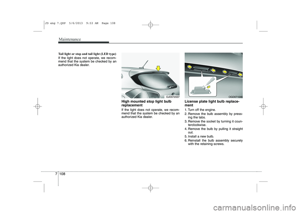
High mounted stop light bulb replacement
If the light does not operate, we recom-
mend that the system be checked by an
authorized Kia dealer.License plate light bulb replace- ment
1. Turn off the engine.
2. Remove the bulb assembly by press-
ing the tabs.
3. Remove the socket by turning it coun- terclockwise.
4. Remove the bulb by pulling it straight out.
5. Install a new bulb.
6. Reinstall the bulb assembly securely with the retaining screws.
OJD072037OGD071046
JD eng 7.QXP 5/6/2013 9:53 AM Page 108
Page 593 of 1206

I3
Index
Battery saver function. . . . . . . . . . . . . . . . . . . . . . . . 4-111
Before driving . . . . . . . . . . . . . . . . . . . . . . . . . . . . . . . . 5-4
Bottle holders . . . . . . . . . . . . . . . . . . . . . . . . . . . . . . 4-158
Brake system . . . . . . . . . . . . . . . . . . . . . . . . . . . . . . . . 5-33
Anti-lock brake system (ABS) . . . . . . . . . . . . . . . . . 5-41
Electric parking brake (EPB) . . . . . . . . . . . . . . . . . 5-37
Electronic stability control (ESC) . . . . . . . . . . . . . . 5-44
Emergency Stop Signal (ESS) . . . . . . . . . . . . . . . . . 5-48
Hill-start assist control (HAC) . . . . . . . . . . . . . . . . 5-48
Power brakes. . . . . . . . . . . . . . . . . . . . . . . . . . . . . . . 5-33
Parking brakes (Hand type) . . . . . . . . . . . . . . . . . . 5-35
Vehicle stability management (VSM) . . . . . . . . . . . 5-47
Brakes/clutch fluid . . . . . . . . . . . . . . . . . . . . . . . . . . . 7-42
Bulb replacement . . . . . . . . . . . . . . . . . . . . . . . . . . . . 7-89
Bulb wattage . . . . . . . . . . . . . . . . . . . . . . . . . . . . . . . . . 8-6
Button start/stop, see engine start/stop button . . . . . 5-9
Calender. . . . . . . . . . . . . . . . . . . . . . . . . . . . . . . . . . . . 4-90
Camera (Rear view) . . . . . . . . . . . . . . . . . . . . . . . . . 4-110
Capacities (Lubricants) . . . . . . . . . . . . . . . . . . . . . . . . 8-8
Care Exterior care . . . . . . . . . . . . . . . . . . . . . . . . . . . . . . 7-110
Interior care. . . . . . . . . . . . . . . . . . . . . . . . . . . . . . . 7-115
Tire care. . . . . . . . . . . . . . . . . . . . . . . . . . . . . . . . . . . 7-55
Cargo area cover . . . . . . . . . . . . . . . . . . . . . . . . . . . . 4-162 Cargo security screen . . . . . . . . . . . . . . . . . . . . . . . . 4-166
Center console storage . . . . . . . . . . . . . . . . . . . . . . . 4-152
Central door lock switch . . . . . . . . . . . . . . . . . . . . . . 4-19
Certification label . . . . . . . . . . . . . . . . . . . . . . . . . . . . 8-11Chains
Tire chains . . . . . . . . . . . . . . . . . . . . . . . . . . . . . . . . . 5-68
Changing tires . . . . . . . . . . . . . . . . . . . . . . . . . . . . . . . 6-10
Checking tire inflation pressure . . . . . . . . . . . . . . . . 7-57
Child restraint system . . . . . . . . . . . . . . . . . . . . . . . . 3-31 ISOFIX system . . . . . . . . . . . . . . . . . . . . . . . . . . . . . 3-37
Seat belt . . . . . . . . . . . . . . . . . . . . . . . . . . . . . . . . . . . 3-34
Tether anchor system . . . . . . . . . . . . . . . . . . . . . . . . 3-36
Child-protector rear door lock . . . . . . . . . . . . . . . . . 4-21
Cigarette lighter . . . . . . . . . . . . . . . . . . . . . . . . . . . . 4-156
Clean air . . . . . . . . . . . . . . . . . . . . . . . . . . . . . . . . . . 4-151
Climate control air filter . . . . . . . . . . . 4-135, 4-147, 7-47
Clock . . . . . . . . . . . . . . . . . . . . . . . . . . . . . . . . . . . . . . 4-90
Clothes hanger . . . . . . . . . . . . . . . . . . . . . . . . . . . . . 4-161Combined instrument, see instrument cluster (Normal vision) . . . . . . . . . . . . . . . . . . . . . . . . . . . . . 4-46
Combined instrument, see instrument cluster (Super vision) . . . . . . . . . . . . . . . . . . . . . . . . . . . . . . 4-59
Compact spare tire . . . . . . . . . . . . . . . . . . . . . . . . . . . 6-15
Compact spare tire replacement . . . . . . . . . . . . . . . . 7-60
Cool box . . . . . . . . . . . . . . . . . . . . . . . . . . . . . . . . . . . 4-153
Coolant . . . . . . . . . . . . . . . . . . . . . . . . . . . . . . . . . . . . . 7-39
Cooling fluid, see engine coolant . . . . . . . . . . . . . . . . 7-40
C
JD eng Index.QXP 5/6/2013 10:37 AM Page 3
Page 598 of 1206

Index
8
I
Key positions . . . . . . . . . . . . . . . . . . . . . . . . . . . . . . . . . 5-5
Keys . . . . . . . . . . . . . . . . . . . . . . . . . . . . . . . . . . . . . . . . 4-4 Label
Air bag warning label . . . . . . . . . . . . . . . . . . . . . . . 3-65
Air conditioner compressor label . . . . . . . . . . . . . . 8-12
Refrigerant label . . . . . . . . . . . . . . . . . . . . . . . . . . . . 8-13
Tire sidewall labeling . . . . . . . . . . . . . . . . . . . . . . . . 7-61
Tire specification and pressure label . . . . . . . . . . . 8-12
Vehicle certification label . . . . . . . . . . . . . . . . . . . . . 8-11
Lane Departure Warning System . . . . . . . . . . . . . . . 5-59
Lane Departure Warning System Mode. . . . . . . . . . 4-69
Lap/shoulder belt . . . . . . . . . . . . . . . . . . . . . . . . . . . . 3-23
LCD display information . . . . . . . . . . . . . . . . . . . . . . 4-73LCD display warnings and indicators (instrument panel display) . . . . . . . . . . . . . . . . . . . . 4-90
Calender . . . . . . . . . . . . . . . . . . . . . . . . . . . . . . . . . . 4-90
Clock . . . . . . . . . . . . . . . . . . . . . . . . . . . . . . . . . . . . . 4-90
Icy road warning . . . . . . . . . . . . . . . . . . . . . . . . . . . 4-91
Outside ambient Temperature . . . . . . . . . . . . . . . . 4-90
LDWS (Lane Departure Warning System) . . . . . . . 5-59
Light bulbs. . . . . . . . . . . . . . . . . . . . . . . . . . . . . . . . . . 7-89 Lighting . . . . . . . . . . . . . . . . . . . . . . . . . . . . . . . . . . . 4-111
AFLS (Adaptive Front Lighting System) . . . . . . . 4-118
Auto light/AFLS position . . . . . . . . . . . . . . . . . . . . 4-113
Battery saver function . . . . . . . . . . . . . . . . . . . . . . 4-111
Daytime running light (DRL) . . . . . . . . . . . . . . . . 4-116
Front fog light . . . . . . . . . . . . . . . . . . . . . . . . . . . . . 4-116
Headlamp delay function . . . . . . . . . . . . . . . . . . . . 4-111
Headlight (Headlamp) welcome function . . . . . . . 4-111
Headlight leveling device . . . . . . . . . . . . . . . . . . . . 4-117
Headlight position . . . . . . . . . . . . . . . . . . . . . . . . . . 4-113
High - beam operation . . . . . . . . . . . . . . . . . . . . . . 4-114
Position light position . . . . . . . . . . . . . . . . . . . . . . . 4-112
Rear fog light. . . . . . . . . . . . . . . . . . . . . . . . . . . . . . 4-116
Static bending light . . . . . . . . . . . . . . . . . . . . . . . . . 4-112
Turn signals . . . . . . . . . . . . . . . . . . . . . . . . . . . . . . . 4-115
Lubricants and capacities . . . . . . . . . . . . . . . . . . . . . . 8-8
Luggage net (holder) . . . . . . . . . . . . . . . . . . . . . . . . 4-162
Luggage rail system . . . . . . . . . . . . . . . . . . . . . . . . . 4-167
Luggage room lamp . . . . . . . . . . . . . . . . . . . . . . . . . 4-125
Luggage side tray . . . . . . . . . . . . . . . . . . . . . . . . . . . 4-155
Luggage tray . . . . . . . . . . . . . . . . . . . . . . . . . . . . . . . 4-154
Lumbar support (Automatic Seat) . . . . . . . . . . . . . . . 3-7
Lumbar support (Manual seat) . . . . . . . . . . . . . . . . . . 3-5
L
K
JD eng Index.QXP 5/6/2013 10:37 AM Page 8
Page 711 of 1206
427
Features of your vehicle
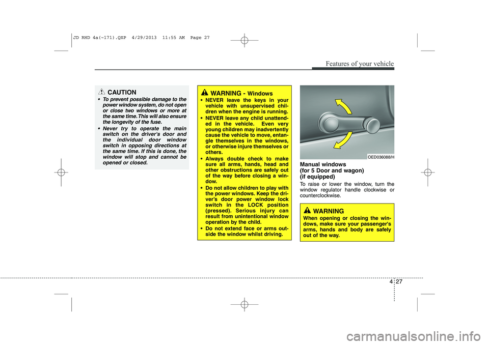
Manual windows
(for 5 Door and wagon)(if equipped)
To raise or lower the window, turn the
window regulator handle clockwise or
counterclockwise.
CAUTION
To prevent possible damage to thepower window system, do not open
or close two windows or more at the same time. This will also ensurethe longevity of the fuse.
Never try to operate the main switch on the driver's door andthe individual door windowswitch in opposing directions at the same time. If this is done, the
window will stop and cannot be opened or closed.WARNING - Windows
NEVER leave the keys in your vehicle with unsupervised chil- dren when the engine is running.
NEVER leave any child unattend- ed in the vehicle. Even very
young children may inadvertently
cause the vehicle to move, entan-
gle themselves in the windows,or otherwise injure themselves or
others.
Always double check to make sure all arms, hands, head and
other obstructions are safely out
of the way before closing a win-
dow.
Do not allow children to play with the power windows. Keep the dri-
ver’s door power window lock
switch in the LOCK position
(pressed). Serious injury can
result from unintentional window
operation by the child.
Do not extend face or arms out- side the window whilst driving.
OED036088/H
WARNING
When opening or closing the win-
dows, make sure your passenger's
arms, hands and body are safely
out of the way.
JD RHD 4a(~171).QXP 4/29/2013 11:55 AM Page 27
Page 714 of 1206
Features of your vehicle
30
4
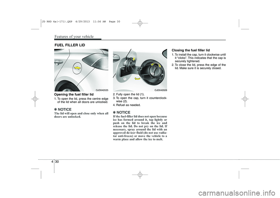
Opening the fuel filler lid
1. To open the lid, press the centre edge
of the lid when all doors are unlocked.
✽✽ NOTICE
The lid will open and close only when all
doors are unlocked.
2. Fully open the lid (1).
3. To open the cap, turn it counterclock- wise (2).
4. Refuel as needed.
✽✽ NOTICE
If the fuel-filler lid does not open because
ice has formed around it, tap lightly or
push on the lid to break the ice and
release the lid. Do not pry on the lid. If
necessary, spray around the lid with an
approved de-icer fluid (do not use radia-
tor anti-freeze) or move the vehicle to awarm place and allow the ice to melt.
Closing the fuel filler lid
1. To install the cap, turn it clockwise until it “clicks”. This indicates that the cap is securely tightened.
2. To close the lid, press the edge of the lid. Make sure it is securely closed.
FUEL FILLER LID
OJD042025OJD042026
JD RHD 4a(~171).QXP 4/29/2013 11:56 AM Page 30
Page 774 of 1206

Features of your vehicle
90
4
LCD DISPLAY WARNINGS AND INDICATORS (INSTRUMENT PANEL DISPLAY)
Calendar / Clock / Outside ambi-
ent Temperature (if equipped)
The monitor will display the outside ambi-
ent temperature, date and time. To change the date, time or temperatureunit(°C
↔ °F), press the SET (2) button
for more than 1 seconds.
Then you will enter the set-up mode and
mode changes in the following order as
you press the SET (2) button less than 1second. HOUR → MINUTE → YEAR → MONTH
→ DAY → 12H/24H → TEMPERATURE
UNIT CHANGE → Escape set-up mode
Press the SET (2) button less than 1 sec- ond to select the mode and set the data
using the UP (1, ) and DOWN (1, )
button whilst the selected setting mode
blinks.
To cancel the SET UP mode, do one of
the following :
- Press the SET button less than 1 sec- ond in set-up temperature unit change mode
- Press the SET button more than 1 sec- ond in any set-up mode
- After 15 seconds without any key press
- Ignition is On or OFF in Set-up mode
- Battery is disconnected Door and tailgate open display
The monitor will display the correspon- ding door or tailgate that is not closed
securely.
OJD042142R
OJD042145R
OJD042143R
JD RHD 4a(~171).QXP 4/29/2013 12:00 PM Page 90
Page 1039 of 1206
What to do in an emergency
10
6
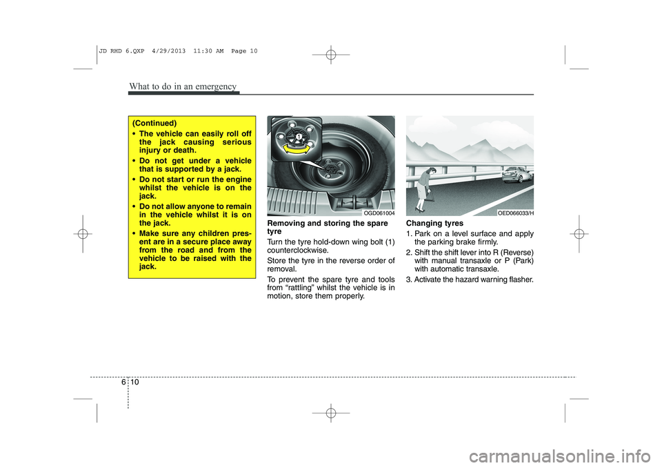
Removing and storing the spare tyre
Turn the tyre hold-down wing bolt (1)
counterclockwise.
Store the tyre in the reverse order of
removal.
To prevent the spare tyre and tools
from “rattling” whilst the vehicle is in
motion, store them properly. Changing tyres
1. Park on a level surface and apply
the parking brake firmly.
2. Shift the shift lever into R (Reverse) with manual transaxle or P (Park)
with automatic transaxle.
3. Activate the hazard warning flasher.
OGD061004
(Continued)
The vehicle can easily roll off the jack causing serious
injury or death.
Do not get under a vehicle that is supported by a jack.
Do not start or run the engine whilst the vehicle is on the
jack.
Do not allow anyone to remain in the vehicle whilst it is on
the jack.
Make sure any children pres- ent are in a secure place away
from the road and from the
vehicle to be raised with the
jack.
OED066033/H
JD RHD 6.QXP 4/29/2013 11:30 AM Page 10
Page 1040 of 1206

611
What to do in an emergency
4. Remove the wheel lug nut wrench,jack, jack handle, and spare tyre
from the vehicle.
5. Block both the front and rear of the wheel that is diagonally opposite
the jack position. 6. Loosen the wheel lug nuts coun-
terclockwise one turn each, but do
not remove any nut until the tyre
has been raised off the ground.
WARNING - Changing a tyre
To prevent vehicle movement
whilst changing a tyre, always
set the parking brake fully,
and always block the wheel
diagonally opposite the wheel
being changed.
We recommend that the wheels of the vehicle be
chocked, and that no person
remain in a vehicle that is
being jacked.
OJD062003OJD062004
JD RHD 6.QXP 4/29/2013 11:30 AM Page 11
Page 1041 of 1206
What to do in an emergency
12
6
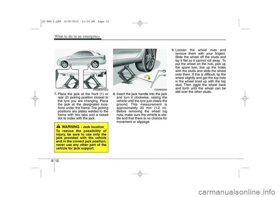
7. Place the jack at the front (1) or
rear (2) jacking position closest to
the tyre you are changing. Place
the jack at the designated loca-
tions under the frame. The jacking
positions are plates welded to the
frame with two tabs and a raised
dot to index with the jack. 8. Insert the jack handle into the jack
and turn it clockwise, raising the
vehicle until the tyre just clears the
ground. This measurement is
approximately 30 mm (1.2 in).
Before removing the wheel lug
nuts, make sure the vehicle is sta-
ble and that there is no chance for
movement or slippage. 9. Loosen the wheel nuts and
remove them with your fingers.Slide the wheel off the studs and
lay it flat so it cannot roll away. To
put the wheel on the hub, pick up
the spare tyre, line up the holeswith the studs and slide the wheel
onto them. If this is difficult, tip thewheel slightly and get the top holein the wheel lined up with the top
stud. Then jiggle the wheel back
and forth until the wheel can be
slid over the other studs.
WARNING - Jack location
To reduce the possibility of
injury, be sure to use only the
jack provided with the vehicle
and in the correct jack position;
never use any other part of the
vehicle for jack support.
OJD062005OVG063015/Q
JD RHD 6.QXP 4/29/2013 11:30 AM Page 12
Page 1042 of 1206
613
What to do in an emergency
10. To reinstall the wheel, hold it onthe studs, put the wheel nuts on the studs and tighten them finger
tight. The nuts should be installedwith their tapered small diameter
ends directed inward. Jiggle thetyre to be sure it is completely
seated, then tighten the nuts as
much as possible with your fin-gers again.
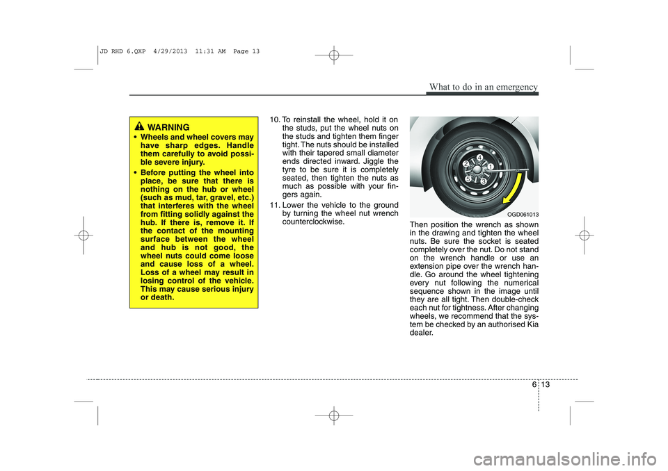
11. Lower the vehicle to the ground by turning the wheel nut wrench
counterclockwise. Then position the wrench as shown
in the drawing and tighten the wheel
nuts. Be sure the socket is seated
completely over the nut. Do not standon the wrench handle or use an
extension pipe over the wrench han-
dle. Go around the wheel tightening
every nut following the numerical
sequence shown in the image until
they are all tight. Then double-check
each nut for tightness. After changing
wheels, we recommend that the sys-
tem be checked by an authorised Kia
dealer.
WARNING
Wheels and wheel covers may have sharp edges. Handle
them carefully to avoid possi-
ble severe injury.
Before putting the wheel into place, be sure that there isnothing on the hub or wheel
(such as mud, tar, gravel, etc.)
that interferes with the wheel
from fitting solidly against the
hub. If there is, remove it. Ifthe contact of the mountingsurface between the wheel
and hub is not good, the
wheel nuts could come looseand cause loss of a wheel.
Loss of a wheel may result in
losing control of the vehicle.
This may cause serious injuryor death.
OGD061013
JD RHD 6.QXP 4/29/2013 11:31 AM Page 13