fuse box KIA CEED 2015 Owners Manual
[x] Cancel search | Manufacturer: KIA, Model Year: 2015, Model line: CEED, Model: KIA CEED 2015Pages: 1210, PDF Size: 35.92 MB
Page 12 of 1210
Your vehicle at a glance
4
2
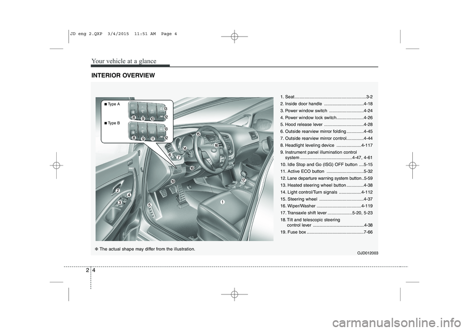
INTERIOR OVERVIEW
1. Seat..........................................................3-2
2. Inside door handle ................................4-18
3. Power window switch ............................4-24
4. Power window lock switch......................4-26
5. Hood release lever ................................4-28
6. Outside rearview mirror folding ..............4-45
7. Outside rearview mirror control..............4-44
8. Headlight leveling device ....................4-117
9. Instrument panel illumination control
system ..........................................4-47, 4-61
10. Idle Stop and Go (ISG) OFF button ....5-15
11. Active ECO button ..............................5-32
12. Lane departure warning system button ..5-59
13. Heated steering wheel button ..............4-38
14. Light control/Turn signals ..................4-112
15. Steering wheel ....................................4-37
16. Wiper/Washer ....................................4-119
17. Transaxle shift lever ....................5-20, 5-23
18. Tilt and telescopic steering control lever ..............................................4-38
19. Fuse box ..............................................7-66
OJD012003
❈ The actual shape may differ from the illustration.
■Type A
■ Type B
JD eng 2.QXP 3/4/2015 11:51 AM Page 4
Page 14 of 1210
Your vehicle at a glance
6
2
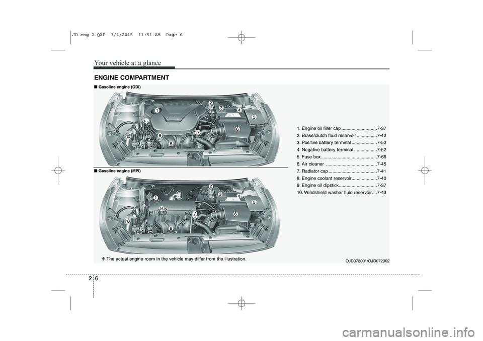
ENGINE COMPARTMENT
OJD072001/OJD072002
❈
The actual engine room in the vehicle may differ from the illustration. 1. Engine oil filler cap ............................7-37
2. Brake/clutch fluid reservoir ................7-42
3. Positive battery terminal ....................7-52
4. Negative battery terminal ..................7-52
5. Fuse box ............................................7-66
6. Air cleaner ........................................7-45
7. Radiator cap ......................................7-41
8. Engine coolant reservoir....................7-40
9. Engine oil dipstick..............................7-37
10. Windshield washer fluid reservoir ....7-43
■■
Gasoline engine (GDI)
■■Gasoline engine (MPI)
JD eng 2.QXP 3/4/2015 11:51 AM Page 6
Page 15 of 1210
27
Your vehicle at a glance
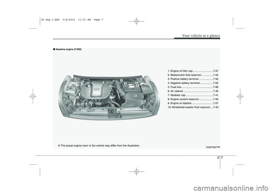
1. Engine oil filler cap ............................7-37
2. Brake/clutch fluid reservoir ................7-42
3. Positive battery terminal ....................7-52
4. Negative battery terminal ..................7-52
5. Fuse box ............................................7-66
6. Air cleaner ........................................7-45
7. Radiator cap ......................................7-41
8. Engine coolant reservoir....................7-40
9. Engine oil dipstick..............................7-37
10. Windshield washer fluid reservoir ....7-43
OJD073077R❈The actual engine room in the vehicle may differ from the illustration.
■
■
Gasoline engine (T-GDI)
JD eng 2.QXP 3/4/2015 11:51 AM Page 7
Page 16 of 1210
OJD072003
❈
The actual engine room in the vehicle may differ from the illustration.
■■
Diesel engine
28
Your vehicle at a glance
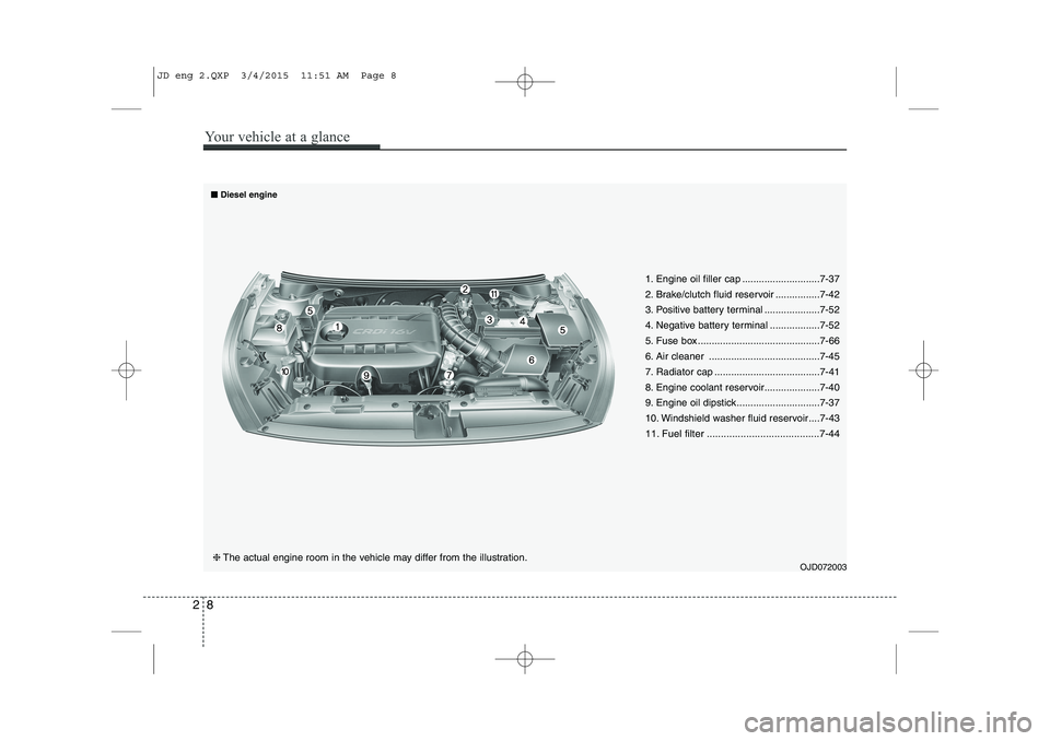
1. Engine oil filler cap ............................7-37
2. Brake/clutch fluid reservoir ................7-42
3. Positive battery terminal ....................7-52
4. Negative battery terminal ..................7-52
5. Fuse box ............................................7-66
6. Air cleaner ........................................7-45
7. Radiator cap ......................................7-41
8. Engine coolant reservoir....................7-40
9. Engine oil dipstick..............................7-37
10. Windshield washer fluid reservoir ....7-43
11. Fuel filter ........................................7-44
JD eng 2.QXP 3/4/2015 11:51 AM Page 8
Page 65 of 1210
349
Safety features of your vehicle
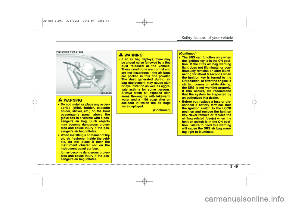
WARNING
If an air bag deploys, there may be a loud noise followed by a fine
dust released in the vehicle.These conditions are normal and
are not hazardous - the air bags
are packed in this fine powder.
The dust generated during air
bag deployment may cause skin
or eye irritation as well as aggra-
vate asthma for some persons.
Always wash all exposed skin
areas thoroughly with lukewarmwater and a mild soap after an
accident in which the air bags
were deployed.
(Continued)(Continued)
The SRS can function only whenthe ignition key is in the ON posi-
tion. If the SRS air bag warning
light does not illuminate, or con-
tinuously remains on after illumi-
nating for about 6 seconds when
the ignition key is turned to the
ON position, or after the engine is
started, comes on while driving,
the SRS is not working properly.
If this occurs, we recommend
that the system be inspected by
an authorized Kia dealer.
Before you replace a fuse or dis- connect a battery terminal, turn
the ignition switch to the LOCK
position and remove the ignition
key. Never remove or replace the
air bag related fuse(s) when the
ignition switch is in the ON posi-
tion. Failure to heed this warning
will cause the SRS air bag warn-
ing light to illuminate.
WARNING
Do not install or place any acces- sories (drink holder, cassette
holder, sticker, etc.) on the front
passenger's panel above the
glove box in a vehicle with a pas-
senger's air bag. Such objects
may become dangerous projec-
tiles and cause injury if the pas-
senger's air bag inflates.
When installing a container of liq- uid air freshener inside the vehi-
cle, do not place it near the
instrument cluster nor on the
instrument panel surface.
It may become dangerous projec-
tiles and cause injury if the pas-
senger's air bag inflates.
B240B05L
Passenger’s front air bag
JD eng 3.QXP 3/4/2015 2:41 PM Page 49
Page 462 of 1210

73
Maintenance
ENGINE COMPARTMENT
OJD072001/OJD072002
❈
The actual engine room in the vehicle may differ from the illustration. 1. Engine oil filler cap
2. Brake/clutch fluid reservoir
3. Positive battery terminal
4. Negative battery terminal
5. Fuse box
6. Air cleaner
7. Radiator cap
8. Engine coolant reservoir
9. Engine oil dipstick
10. Windshield washer fluid reservoir
■■
Gasoline engine (GDI)
■■Gasoline engine (MPI)
JD eng 7.QXP 3/4/2015 3:29 PM Page 3
Page 463 of 1210

Maintenance
4
7
1. Engine oil filler cap
2. Brake/clutch fluid reservoir
3. Positive battery terminal
4. Negative battery terminal
5. Fuse box
6. Air cleaner
7. Radiator cap
8. Engine coolant reservoir
9. Engine oil dipstick
10. Windshield washer fluid reservoir
OJD073077R❈ The actual engine room in the vehicle may differ from the illustration.
■
■
Gasoline engine (T-GDI)
JD eng 7.QXP 3/4/2015 3:29 PM Page 4
Page 464 of 1210
75
Maintenance
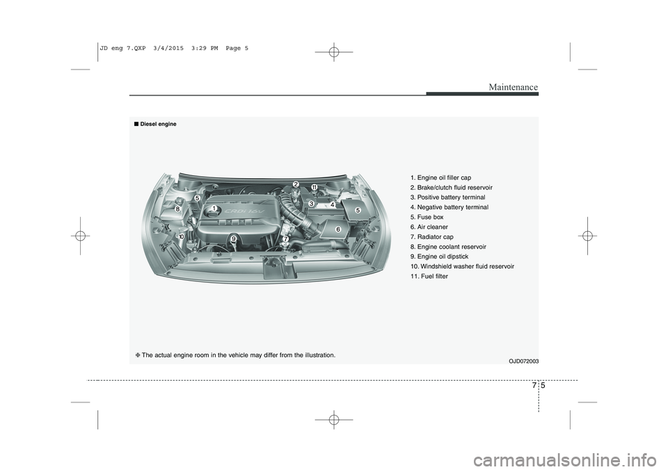
OJD072003
❈
The actual engine room in the vehicle may differ from the illustration. 1. Engine oil filler cap
2. Brake/clutch fluid reservoir
3. Positive battery terminal
4. Negative battery terminal
5. Fuse box
6. Air cleaner
7. Radiator cap
8. Engine coolant reservoir
9. Engine oil dipstick
10. Windshield washer fluid reservoir
11. Fuel filter
■■
Diesel engine
JD eng 7.QXP 3/4/2015 3:29 PM Page 5
Page 528 of 1210

769
Maintenance
2. Remove the fuse box cover by press-ing the tap and pulling up. When the
blade type fuse is disconnected,
remove it by using the clip designed forchanging fuses located in the engine
room fuse box. Upon removal, secure-
ly insert reserve fuse of equal quantity.
3. Check the removed fuse; replace it if it is blown. To remove or insert the fuse,use the fuse puller in the engine com-
partment fuse panel.
4. Push in a new fuse of the same rating, and make sure it fits tightly in the clips.
If it fits loosely, we recommend that you
consult an authorized Kia dealer.
Main fuse
Electrical equipments are not working
even though inner panel and engine
compartment fuses are not blown, or
many of these are not working at the
same time, it may has blown the main
fuse(Battery Fuse Terminal type) inside
of the battery(+) cap.
If the main fuse is blown, it must be
removed as follows: 1. Turn off the engine.
2. Disconnect the negative battery cable.
3. Remove the nuts shown in the picture
above.
4. Replace the fuse with a new one of the same rating.
5. Reinstall in the reverse order of removal.
OGD071020
CAUTION
After checking the fuse box in the
engine compartment, install thefuse box cover securely. If not,water leaking may cause electrical
failures.
CAUTION
After checking the main fuse, install the cover securely whenyou close the cover, check the
locking sound.
If not, electrical failures mayoccur from water leaking in.
Visually inspect the battery cap for secure closing. If the batterycap is not securely latched, the
electrical system may be dam-aged to due influx of moisture into the system.
JD eng 7.QXP 3/4/2015 3:31 PM Page 69
Page 531 of 1210
Maintenance
72
7
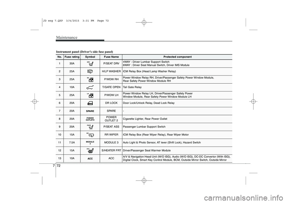
Instrument panel (Driver’s side fuse panel)
No.Fuse ratingSymbolFuse NameProtected component
130ADRVP/SEAT DRV4WAY : Driver Lumbar Support Switch
6WAY : Driver Seat Manual Switch, Driver IMS Module
225AH/LP WASHERICM Relay Box (Head Lamp Washer Relay)
325ARHP/WDW RHPower Window Relay RH, Driver/Passenger Safety Power Window Module,
Rear Safety Power Window Module RH
410AT/GATE OPENTail Gate Relay
525ALHP/WDW LHPower Window Relay LH, Driver/Passenger Safety Power
Window Module, Rear Safety Power Window Module LH
620ADR LOCKDoor Lock/Unlock Relay, Dead Lock Relay
720ASPARESPARE-
820APOWER
OUTLET2POWER
OUTLET 2Cigarette Lighter, Rear Power Outlet
920APASSP/SEAT ASSPassenger Lumbar Support Switch
1015ARRRR WIPERICM Relay Box (Rear Wiper Relay), Rear Wiper Motor
117.5AMODULE 3MODULE 3Auto Light & Photo Sensor, AT lever (Shift Lock), Hazard Switch
1215AFRTS/HEATER FRTDriver/Passenger Seat Warmer Module
1310AACCACCA/V & Navigation Head Unit (W/O ISG), Audio (W/O ISG), DC-DC Convertor (With ISG),
Digital Clock, Smart Key Control Module, BCM, Outside Mirror Switch, Outside Mirror
JD eng 7.QXP 3/4/2015 3:31 PM Page 72