tow KIA CEED 2016 User Guide
[x] Cancel search | Manufacturer: KIA, Model Year: 2016, Model line: CEED, Model: KIA CEED 2016Pages: 643, PDF Size: 38.19 MB
Page 127 of 643
Features of your vehicle
44
4
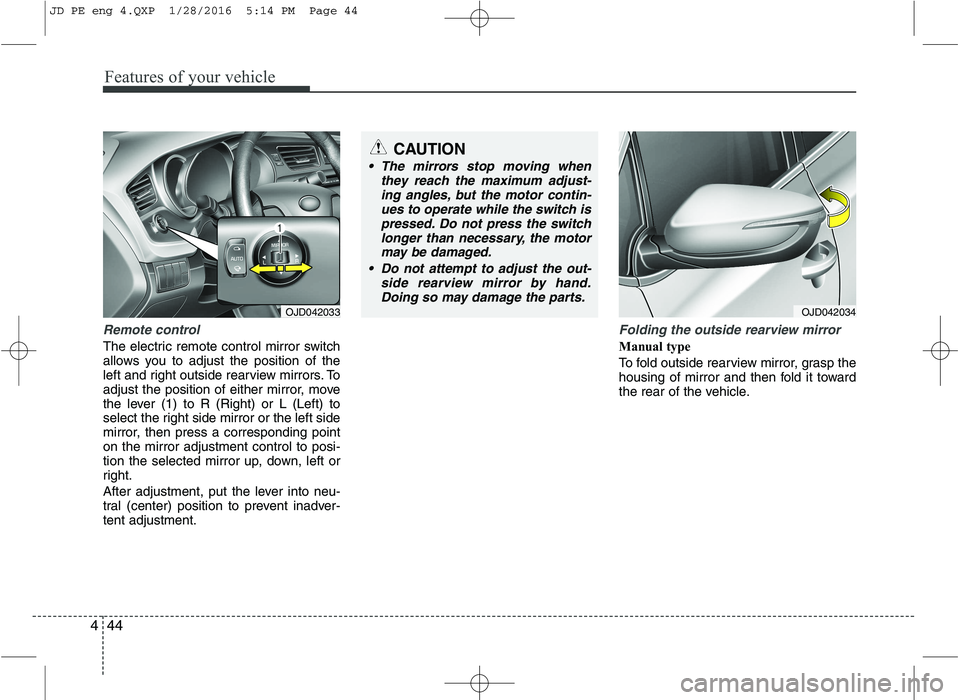
Remote control
The electric remote control mirror switch
allows you to adjust the position of the
left and right outside rearview mirrors. To
adjust the position of either mirror, move
the lever (1) to R (Right) or L (Left) to
select the right side mirror or the left side
mirror, then press a corresponding pointon the mirror adjustment control to posi-
tion the selected mirror up, down, left or
right.
After adjustment, put the lever into neu-
tral (center) position to prevent inadver-tent adjustment.
Folding the outside rearview mirror
Manual type
To fold outside rearview mirror, grasp the
housing of mirror and then fold it toward
the rear of the vehicle.
CAUTION
The mirrors stop moving when
they reach the maximum adjust-ing angles, but the motor contin-ues to operate while the switch is
pressed. Do not press the switchlonger than necessary, the motormay be damaged.
Do not attempt to adjust the out- side rearview mirror by hand.
Doing so may damage the parts.
OJD042033OJD042034
JD PE eng 4.QXP 1/28/2016 5:14 PM Page 44
Page 132 of 643

449
Features of your vehicle
Manual transaxle shift indicator (if equipped)
This indicator informs you which gear is
desired while driving to save fuel.
For example: Indicates that shifting up to the 3rdgear is desired (currently the shift
lever is in the 2nd or 1st gear).
: Indicates that shifting down to the 3rd gear is desired (currently the
shift lever is in the 4th or 5th gear).
You can turn off the indicator. Refer to
“User setting” in this chapter. Automatic transaxle shift position indicator (if equipped)
The indicator displays which automatic
transaxle shift lever is selected.
OJD042233OJD042231/OJD042232
CAUTION
If the gauge pointer moves beyond
the normal range area toward the“130°C”, it indicates overheating that may damage the engine.
WARNING
Never remove the radiator cap
when the engine is hot. The enginecoolant is under pressure and
could cause severe burns. Wait
until the engine is cool before
adding coolant to the reservoir.
JD PE eng 4.QXP 1/28/2016 5:15 PM Page 49
Page 147 of 643

Features of your vehicle
64
4
Engine coolant temperature gauge
This gauge shows the temperature of the
engine coolant when the ignition switchis ON.
Do not continue driving with an overheat-
ed engine. If your vehicle overheats, refer
to “If the engine overheats” in chapter 6. Manual transaxle shift indicator
This indicator informs you which gear is
desired while driving to save fuel.
For example
: Indicates that shifting up to the 3rdgear is desired (currently the shift
lever is in the 2nd or 1st gear).
: Indicates that shifting down to the 3rd gear is desired (currently the
shift lever is in the 4th or 5th gear).
OJD042236/OJD042237
CAUTION
If the gauge pointer moves beyond
the normal range area toward the“130°C” position, it indicates over-heating that may damage the engine.
WARNING
Never remove the radiator cap
when the engine is hot. The enginecoolant is under pressure and
could cause severe burns. Wait
until the engine is cool before
adding coolant to the reservoir.
OJD043250
■ Type B
■Type A
OJD045176L
JD PE eng 4.QXP 1/28/2016 5:16 PM Page 64
Page 178 of 643
495
Features of your vehicle
Non-operational conditions of rear parking assist system
The rear parking assist system may
not operate properly when:
1. Moisture is frozen to the sensor. (It willoperate normally when the moisture has been cleared.)
2. The sensor is covered with foreign matter, such as snow or water, or the
sensor cover is blocked. (It will operate
normally when the material is removed
or the sensor is no longer blocked.)
3. Driving on uneven road surfaces (unpaved roads, gravel, bumps, gradi-ent).
4. Objects generating excessive noise (vehicle horns, loud motorcycle
engines, or truck air brakes) are within
range of the sensor.
5. Heavy rain or water spray exists.
6. Wireless transmitters or mobile phones are within range of the sensor.
7. Trailer towing. The detecting range may decrease when:
1. The sensor is stained with foreign mat-
ter such as snow or water. (The sens-
ing range will return to normal when
removed.)
2. Outside air temperature is extremely hot or cold.
The following objects may not be rec-
ognized by the sensor:
1. Sharp or slim objects such as ropes, chains or small poles.
2. Objects which tend to absorb the sen- sor frequency such as clothes, spongy
material or snow.
3. Undetectable objects smaller than 1 m (40 in.) and narrower than 14 cm (6 in.)
in diameter. Rear parking assist system pre- cautions
The rear parking assist system may
not sound sequentially depending on the speed and shapes of the objectsdetected.
The rear parking assist system may malfunction if the vehicle bumperheight or sensor installation has been
modified or damaged. Any non-factory
installed equipment or accessories
may also interfere with the sensor per-
formance.
The sensor may not recognize objects less than 30 cm (11.8 in.) from the sen-
sor, or it may sense an incorrect dis-
tance. Use caution.
When the sensor is frozen or stained with snow, dirt, or water, the sensor
may be inoperative until the stains are
removed using a soft cloth.
Do not push, scratch or strike the sen- sor. Sensor damage could occur.
JD PE eng 4.QXP 1/28/2016 5:18 PM Page 95
Page 205 of 643
Features of your vehicle
122
4
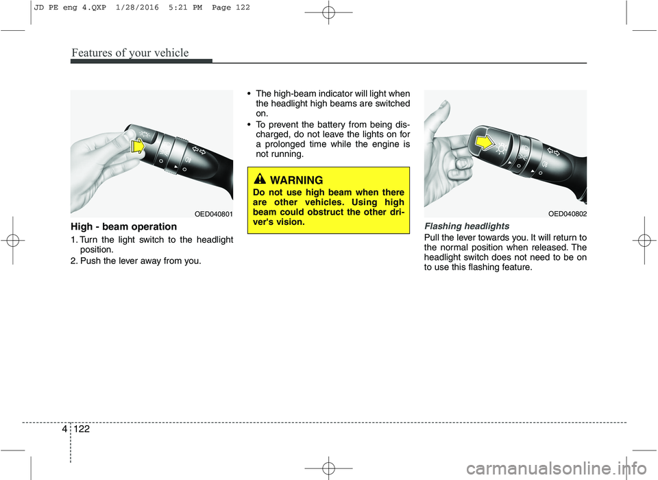
High - beam operation
1. Turn the light switch to the headlight
position.
2. Push the lever away from you. The high-beam indicator will light when
the headlight high beams are switched on.
To prevent the battery from being dis- charged, do not leave the lights on fora prolonged time while the engine is
not running.Flashing headlights
Pull the lever towards you. It will return to
the normal position when released. The
headlight switch does not need to be on
to use this flashing feature.
WARNING
Do not use high beam when there
are other vehicles. Using highbeam could obstruct the other dri-ver's vision.
OED040801OED040802
JD PE eng 4.QXP 1/28/2016 5:21 PM Page 122
Page 212 of 643

4129
Features of your vehicle
Windshield washers (front) (if equipped)
In the O (Off) position, pull the lever gen-
tly toward you to spray washer fluid on
the windshield and to run the wipers 1-3
cycles. Use this function when the windshield is
dirty.
The spray and wiper operation will con-
tinue until you release the lever.
If the washer does not work, check the
washer fluid level. If the fluid level is not
sufficient, you will need to add appropri-
ate non-abrasive windshield washer fluid
to the washer reservoir.
The reservoir filler neck is located in the
front of the engine compartment on the
passenger side.
OXM049048E
WARNING
Do not use the washer in freezing
temperatures without first warming
the windshield with the defrosters;
the washer solution could freeze on
the windshield and obscure yourvision.
CAUTION
To prevent possible damage to the wipers or windshield, do notoperate the wipers when the
windshield is dry.
To prevent damage to the wiper blades, do not use gasoline,kerosene, paint thinner, or other
solvents on or near them.
To prevent damage to the wiper arms and other components, donot attempt to move the wipers
manually.
CAUTION
To prevent possible damage to the
washer pump, do not operate thewasher when the fluid reservoir is empty.
JD PE eng 4.QXP 1/28/2016 5:21 PM Page 129
Page 221 of 643
Features of your vehicle
138
4
Mode selection
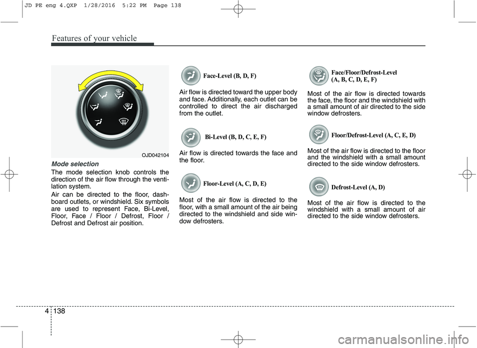
The mode selection knob controls the
direction of the air flow through the venti-lation system.
Air can be directed to the floor, dash-
board outlets, or windshield. Six symbols
are used to represent Face, Bi-Level,
Floor, Face / Floor / Defrost, Floor /Defrost and Defrost air position.
Face-Level (B, D, F)
Air flow is directed toward the upper body
and face. Additionally, each outlet can becontrolled to direct the air dischargedfrom the outlet.
Bi-Level (B, D, C, E, F)
Air flow is directed towards the face and
the floor.
Floor-Level (A, C, D, E)
Most of the air flow is directed to the
floor, with a small amount of the air beingdirected to the windshield and side win-
dow defrosters.
Face/Floor/Defrost-Level
(A, B, C, D, E, F)
Most of the air flow is directed towards
the face, the floor and the windshield witha small amount of air directed to the side
window defrosters.
Floor/Defrost-Level (A, C, E, D)
Most of the air flow is directed to the floorand the windshield with a small amount
directed to the side window defrosters.
Defrost-Level (A, D)
Most of the air flow is directed to thewindshield with a small amount of air
directed to the side window defrosters.
OJD042104
JD PE eng 4.QXP 1/28/2016 5:22 PM Page 138
Page 232 of 643
4149
Features of your vehicle
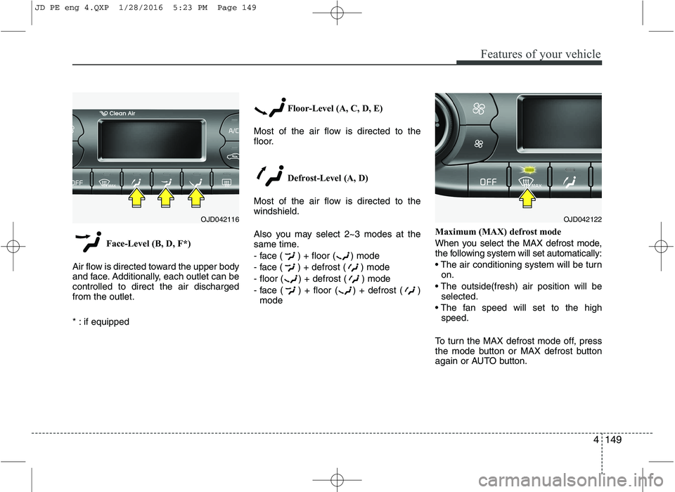
Face-Level (B, D, F*)
Air flow is directed toward the upper body
and face. Additionally, each outlet can becontrolled to direct the air dischargedfrom the outlet.
* : if equipped Floor-Level (A, C, D, E)
Most of the air flow is directed to the
floor.
Defrost-Level (A, D)
Most of the air flow is directed to thewindshield.
Also you may select 2~3 modes at the
same time.
- face ( ) + floor ( ) mode
- face ( ) + defrost ( ) mode
- floor ( ) + defrost ( ) mode
- face ( ) + floor ( ) + defrost ( ) mode Maximum (MAX) defrost mode
When you select the MAX defrost mode,
the following system will set automatically:
on.
selected.
speed.
To turn the MAX defrost mode off, press
the mode button or MAX defrost button
again or AUTO button.
OJD042116OJD042122
JD PE eng 4.QXP 1/28/2016 5:23 PM Page 149
Page 242 of 643
4159
Features of your vehicle
This indicator illuminates
when the auto defoggingsystem senses the moistureof inside the windshield and
operates.
If more moisture is in the vehicle, higher
steps operate as follow.
Step 1 : Operating the air conditioning
Step 2 : Outside air position
Step 3 : Blowing air flow toward the wind- shield
Step 4 : Increasing air flow toward the windshield
If your vehicle is equipped with the auto
defogging system, it is automatically acti-
vated when the conditions are met.
However, if you would like to cancel the
auto defogging system, press the front
defroster button 4 times within 2 seconds
while pressing the AUTO button. The
indicator will blink 3 times to notify you
that the system is cancelled. To use the
auto defogging system again, follow the
procedures mentioned above.
If the battery has been disconnected or
discharged, it resets to the auto defog-
ging status.✽✽ NOTICE
If the A/C off is manually selected while
the auto defogging system is on, the auto
defogging indicator will blink 3 times to
give notice that the A/C off can not be
selected.
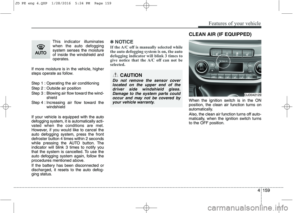
When the ignition switch is in the ON
position, the clean air function turns on
automatically.
Also, the clean air function turns off auto-
matically, when the ignition switch turnsto the OFF position.
CAUTION
Do not remove the sensor cover located on the upper end of the driver side windshield glass. Damage to the system parts could
occur and may not be covered by your vehicle warranty.
OJD042129
CLEAN AIR (IF EQUIPPED)
JD PE eng 4.QXP 1/28/2016 5:24 PM Page 159
Page 258 of 643
4175
Features of your vehicle
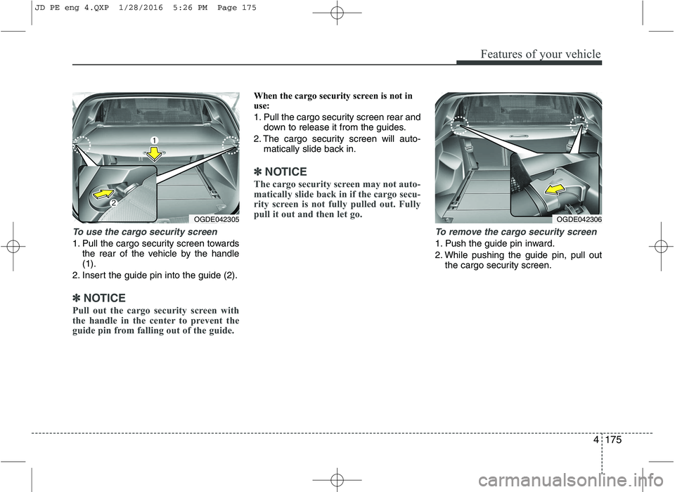
To use the cargo security screen
1. Pull the cargo security screen towardsthe rear of the vehicle by the handle (1).
2. Insert the guide pin into the guide (2).
✽✽ NOTICE
Pull out the cargo security screen with
the handle in the center to prevent the
guide pin from falling out of the guide.
When the cargo security screen is not in
use:
1. Pull the cargo security screen rear and down to release it from the guides.
2. The cargo security screen will auto- matically slide back in.
✽✽ NOTICE
The cargo security screen may not auto-
matically slide back in if the cargo secu-
rity screen is not fully pulled out. Fully
pull it out and then let go.
To remove the cargo security screen
1. Push the guide pin inward.
2. While pushing the guide pin, pull out the cargo security screen.
OGDE042305OGDE042306
JD PE eng 4.QXP 1/28/2016 5:26 PM Page 175