KIA FORTE 2017 Owners Manual
Manufacturer: KIA, Model Year: 2017, Model line: FORTE, Model: KIA FORTE 2017Pages: 595, PDF Size: 11.5 MB
Page 541 of 595

779
Maintenance
Engine compartment fuse panel
Fuse Name Fuse rating Circuit Protected
MULTI FUSE MDPS 80A MDPS Unit
B+1 60A Smart Junction Block (ARISU-LT IPS 1 (4CH), Fuse - MODULE6, MODULE7, MODULE9,
P/WDW LH, P/WDW RH, TRUNK)
ABS 1 40A ESC Module
C/FAN 40A C/Fan Relay
RR HTD 40A RR HTD Relay
BLOWER 40A Blower Relay
GSL PTC HEATER 60A GSL PTC Heater Relay
B+2 60A Smart Junction Block (ARISU-LT IPS 3 (4CH), ARISU-LT IPS 4 (4CH), IPS 5 (2CH), Fuse -
PDM 1, P/SEAT DRV BRAKE SWITCH, S/HEATER RR)
FUSEB/UP LAMP 10A A/T,DCT : Electro Chromic Mirror, Audio, A/V & Navigation Head Unit, Rear Combination
Lamp (In) LH/RH M/T : Back-Up Lamp Switch
TCU 1 15A A/T : Transaxle Range Switch, DCT : Transaxle Range Switch, TCM
ABS 3 10A ESC Module
ECU 3 10A ECM/PCM, Vacuum Pump
A/CON SWITCH 10A A/C Control Module, Blower Motor, Blower Relay, ECM/PCM, Blower Resistor
WIPER FRT 10A ECM/PCM, Wiper Motor, E/R Junction Block (Wiper FRT Relay)
B+3 50A Smart Junction Block (Leak Current Autocut Device, Fuse - PDM 2, DR LOCK, SUNROOF)
ECU 6 40A EMS Block (Engine Control Relay, Fuse - ECU 4, A/CON, F/PUMP)
GSL PTC HEATER 50A GSL PTC HEATER RELAY
DEICER 15A ICM Relay Box (Front Deicer Relay)
STOP LAMP 10A Stop Signal Electronic Module
Page 542 of 595
Maintenance
80 7
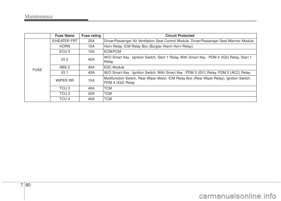
Fuse Name Fuse rating Circuit Protected
FUSES/HEATER FRT 20A Driver/Passenger Air Ventilation Seat Control Module, Driver/Passenger Seat Warmer Module
HORN 15A Horn Relay, ICM Relay Box (Burglar Alarm Horn Relay)
ECU 5 15A ECM/PCM
IG 2 40AW/O Smart Key : Ignition Switch, Start 1 Relay, With Smart Key : PDM 4 (IG2) Relay, Start 1
Relay
ABS 2 40A ESC Module
IG 1 40A W/O Smart Key : Ignition Switch, With Smart Key : PDM 3 (IG1) Relay, PDM 2 (ACC) Relay
WIPER RR 15A Multifunction Switch, Rear Wiper Motor, ICM Relay Box (Rear Wiper Relay), Ignition Switch,
PDM 4 (IG2) Relay
TCU 3 40A TCM
TCU 2 20A TCM
TCU 4 40A TCM
Page 543 of 595
781
Maintenance
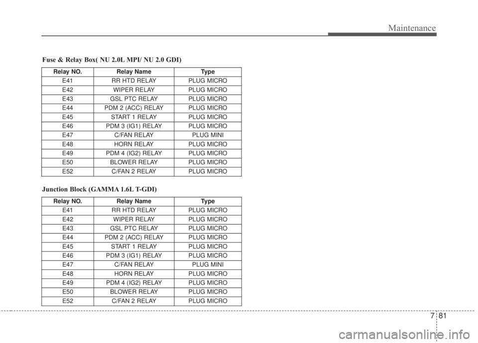
Fuse & Relay Box( NU 2.0L MPI/ NU 2.0 GDI)
Relay NO. Relay Name Type
E41 RR HTD RELAY PLUG MICRO
E42 WIPER RELAY PLUG MICRO
E43 GSL PTC RELAY PLUG MICRO
E44 PDM 2 (ACC) RELAY PLUG MICRO
E45 START 1 RELAY PLUG MICRO
E46 PDM 3 (IG1) RELAY PLUG MICRO
E47 C/FAN RELAY PLUG MINI
E48 HORN RELAY PLUG MICRO
E49 PDM 4 (IG2) RELAY PLUG MICRO
E50 BLOWER RELAY PLUG MICRO
E52 C/FAN 2 RELAY PLUG MICRO
Junction Block (GAMMA 1.6L T-GDI)
Relay NO. Relay Name Type
E41 RR HTD RELAY PLUG MICRO
E42 WIPER RELAY PLUG MICRO
E43 GSL PTC RELAY PLUG MICRO
E44 PDM 2 (ACC) RELAY PLUG MICRO
E45 START 1 RELAY PLUG MICRO
E46 PDM 3 (IG1) RELAY PLUG MICRO
E47 C/FAN RELAY PLUG MINI
E48 HORN RELAY PLUG MICRO
E49 PDM 4 (IG2) RELAY PLUG MICRO
E50 BLOWER RELAY PLUG MICRO
E52 C/FAN 2 RELAY PLUG MICRO
Page 544 of 595

Maintenance
82 7
EMS Block (NU 2.0L MPI)
Fuse Name Fuse rating Circuit Protected
F/PUMP 20A F/Pump Relay
ECU 4 15A PCM
A/CON 15A A/CON COMP Relay
INJECTOR 10A EMS Block (F/Pump Relay)
SPARE 10A -
IGN COIL 20A Ignition Coil #1/#2/#3/#4, EMS Block (F/PUMP Relay)
ECU 1 20A ECM/PCM
SENSOR 2 10AOxygen Sensor (Up), Oxygen Sensor (Down), Variable Intake Solenoid Valve, EMS Block (A/CON
COMP Relay) Purge Control Solenoid Valve, Canister Close Valve, E/R Junction Block (C/Fan 2 Relay)
SENSOR 1 10AOil Control Valve #1 (Intake), Oil Control Valve #2 (Exhaust), Oil Control Valve #3 (Signal), Electronic
Thermostat
SPARE 10A -
SPARE 15A -
SPARE 20A -
Relay Name Type
ENGINE CONTROL RELAY PCB
A/CON COMP RELAY PLUG MICRO
F/PUMP RELAY PLUG MICRO
Page 545 of 595
783
Maintenance
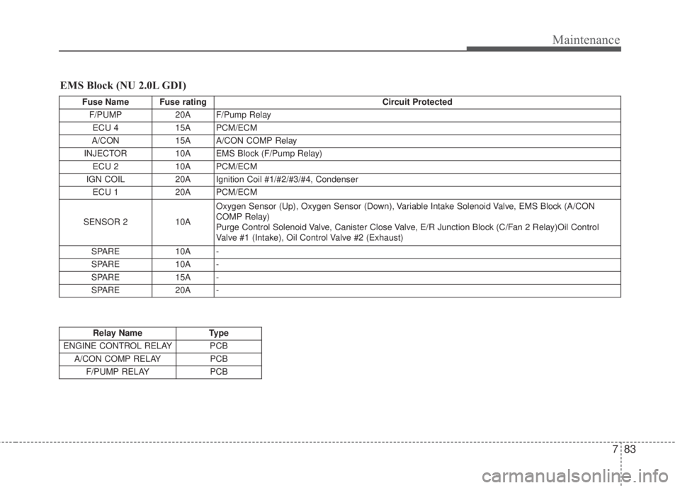
EMS Block (NU 2.0L GDI)
Fuse Name Fuse rating Circuit Protected
F/PUMP 20A F/Pump Relay
ECU 4 15A PCM/ECM
A/CON 15A A/CON COMP Relay
INJECTOR 10A EMS Block (F/Pump Relay)
ECU 2 10A PCM/ECM
IGN COIL 20A Ignition Coil #1/#2/#3/#4, Condenser
ECU 1 20A PCM/ECM
SENSOR 2 10AOxygen Sensor (Up), Oxygen Sensor (Down), Variable Intake Solenoid Valve, EMS Block (A/CON
COMP Relay)
Purge Control Solenoid Valve, Canister Close Valve, E/R Junction Block (C/Fan 2 Relay)Oil Control
Valve #1 (Intake), Oil Control Valve #2 (Exhaust)
SPARE 10A -
SPARE 10A -
SPARE 15A -
SPARE 20A -
Relay Name Type
ENGINE CONTROL RELAY PCB
A/CON COMP RELAY PCB
F/PUMP RELAY PCB
Page 546 of 595
Maintenance
84 7
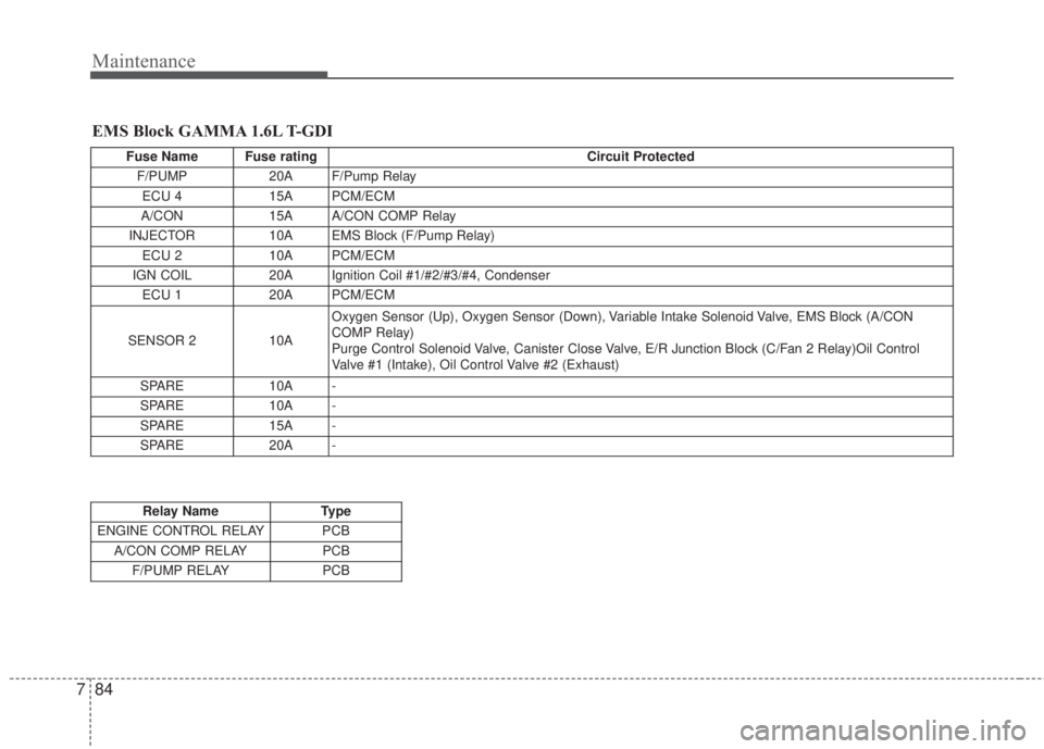
EMS Block GAMMA 1.6L T-GDI
Fuse Name Fuse rating Circuit Protected
F/PUMP 20A F/Pump Relay
ECU 4 15A PCM/ECM
A/CON 15A A/CON COMP Relay
INJECTOR 10A EMS Block (F/Pump Relay)
ECU 2 10A PCM/ECM
IGN COIL 20A Ignition Coil #1/#2/#3/#4, Condenser
ECU 1 20A PCM/ECM
SENSOR 2 10AOxygen Sensor (Up), Oxygen Sensor (Down), Variable Intake Solenoid Valve, EMS Block (A/CON
COMP Relay)
Purge Control Solenoid Valve, Canister Close Valve, E/R Junction Block (C/Fan 2 Relay)Oil Control
Valve #1 (Intake), Oil Control Valve #2 (Exhaust)
SPARE 10A -
SPARE 10A -
SPARE 15A -
SPARE 20A -
Relay Name Type
ENGINE CONTROL RELAY PCB
A/CON COMP RELAY PCB
F/PUMP RELAY PCB
Page 547 of 595
785
Maintenance
LIGHT BULBS
Use only the bulbs of the specified
wattage.
If you don’t have necessary tools, the
correct bulbs and the expertise, con-
sult an authorized Kia dealer. In
many cases, it is difficult to replace
vehicle light bulbs because other
parts of the vehicle must be removed
before you can get to the bulb. This is
especially true if you have to remove
the headlight assembly to get to the
bulb(s). Removing/installing the
headlight assembly can result in
damage to the vehicle.Front lights replacement
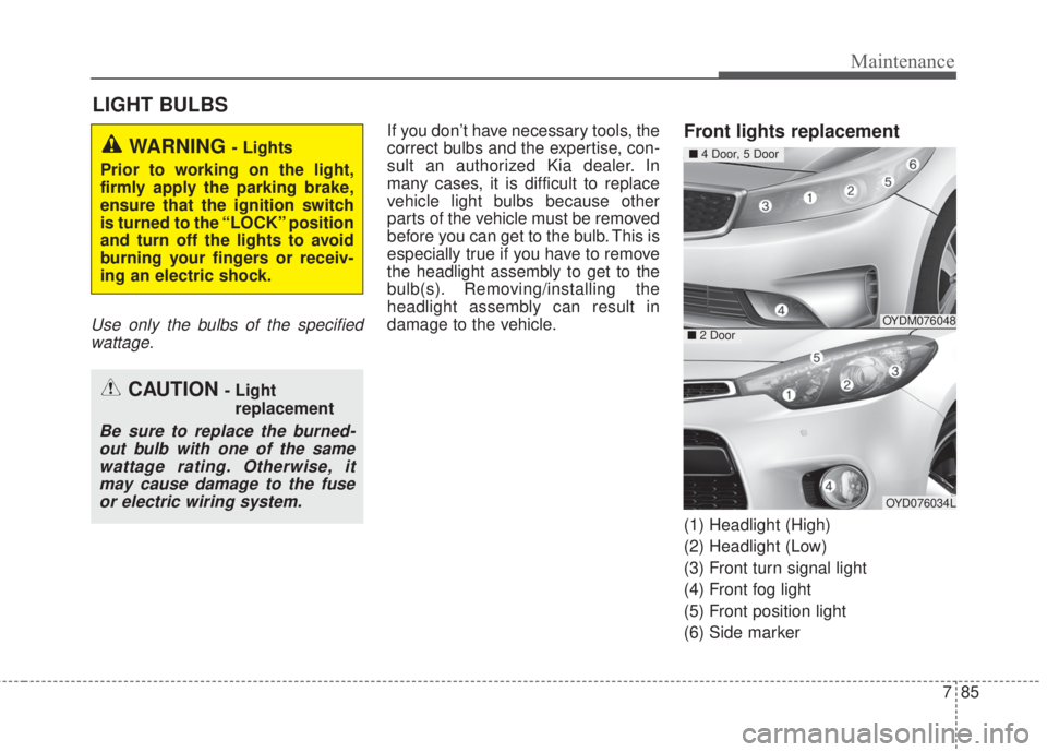
(1) Headlight (High)
(2) Headlight (Low)
(3) Front turn signal light
(4) Front fog light
(5) Front position light
(6) Side marker
WARNING - Lights
Prior to working on the light,
firmly apply the parking brake,
ensure that the ignition switch
is turned to the “LOCK” position
and turn off the lights to avoid
burning your fingers or receiv-
ing an electric shock.
CAUTION - Light
replacement
Be sure to replace the burned-
out bulb with one of the same
wattage rating. Otherwise, it
may cause damage to the fuse
or electric wiring system.
OYDM076048
OYD076034L
■4 Door, 5 Door
■2 Door
Page 548 of 595
Maintenance
86 7
Headlight bulbAlways handle them carefully, and
avoid scratches and abrasions. If the
bulbs are lit, avoid contact with liq-
uids. Never touch the glass with bare
hands. Residual oil may cause the
bulb to overheat and burst when lit. A
bulb should be operated only when
installed in a headlight.
If a bulb becomes damaged or
cracked, replace it immediately and
carefully dispose of it.
Wear eye protection when changing
a bulb. Allow the bulb to cool down
before handling it.Headlight (bulb type)
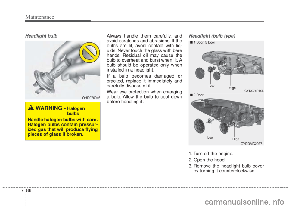
1. Turn off the engine.
2. Open the hood.
3. Remove the headlight bulb cover
by turning it counterclockwise.
OHD076046
WARNING-Halogen
bulbs
Handle halogen bulbs with care.
Halogen bulbs contain pressur-
ized gas that will produce flying
pieces of glass if broken.
OYD076010L
OYDDMC20271
■4 Door, 5 Door
■2 Door
LowHIgh
LowHIgh
Page 549 of 595
787
Maintenance
4. Disconnect the headlight bulb
socket-connector.
5. Remove the bulb from the head-
light assembly.
6. Install a new headlight bulb.
7. Connect the headlight bulb socket-
connector.
8. Install the headlight bulb cover by
turning it clockwise.
If the headlight aiming adjustment is
necessary after the headlight
assembly is reinstalled, consult an
authorized Kia dealer.Front side marker/Front turn sig-
nal light
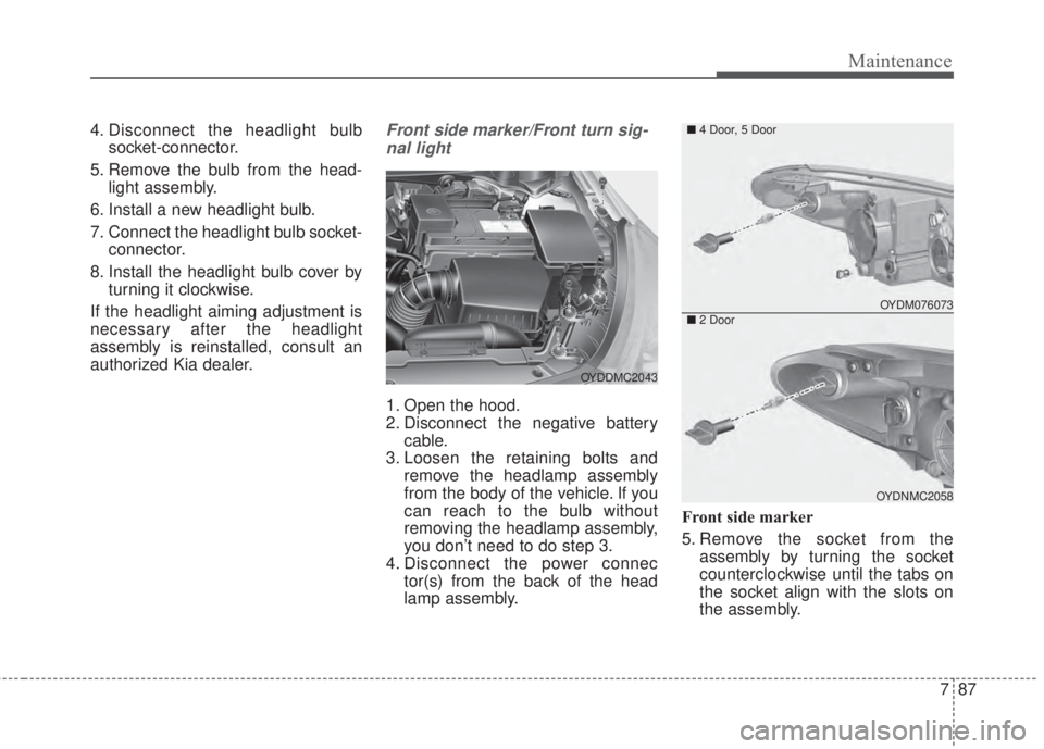
1. Open the hood.
2. Disconnect the negative battery
cable.
3. Loosen the retaining bolts and
remove the headlamp assembly
from the body of the vehicle. If you
can reach to the bulb without
removing the headlamp assembly,
you don’t need to do step 3.
4. Disconnect the power connec
tor(s) from the back of the head
lamp assembly.Front side marker
5. Remove the socket from the
assembly by turning the socket
counterclockwise until the tabs on
the socket align with the slots on
the assembly.
OYDDMC2043
OYDM076073
OYDNMC2058
■4 Door, 5 Door
■2 Door
Page 550 of 595
Maintenance
88 7
6. Pull the bulb out of the socket.
7. Insert a new bulb.
8. Install the socket in the assembly
by aligning the tabs on the socket
with the slots in the assembly.
Push the socket into assembly
and turn the socket clockwise.
9. Reinstall the headlamp assembly,
bumper to the body of the vehicle.
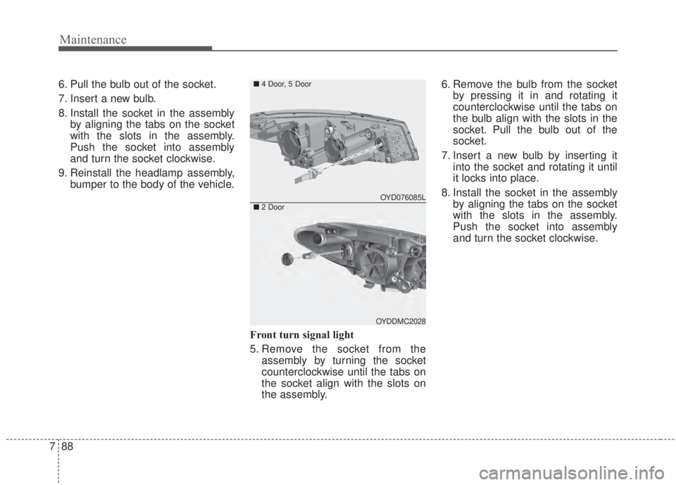
Front turn signal light
5. Remove the socket from the
assembly by turning the socket
counterclockwise until the tabs on
the socket align with the slots on
the assembly.6. Remove the bulb from the socket
by pressing it in and rotating it
counterclockwise until the tabs on
the bulb align with the slots in the
socket. Pull the bulb out of the
socket.
7. Insert a new bulb by inserting it
into the socket and rotating it until
it locks into place.
8. Install the socket in the assembly
by aligning the tabs on the socket
with the slots in the assembly.
Push the socket into assembly
and turn the socket clockwise.
OYD076085L
OYDDMC2028
■4 Door, 5 Door
■2 Door