OBD port KIA FORTE 2020 User Guide
[x] Cancel search | Manufacturer: KIA, Model Year: 2020, Model line: FORTE, Model: KIA FORTE 2020Pages: 568, PDF Size: 8.58 MB
Page 116 of 568

431
Features of your vehicle
Power windows
The ignition switch must be in the ON
position for power windows to oper-
ate.
Each door has a power window
switch that controls the door's win-
dow. The driver has a power window
lock button which can block the oper-
ation of rear passenger windows.
The power windows can be operated
for approximately 10 minutes after
the ignition key is removed or is set
to the to the ACC or LOCK position.
However, if the front doors are
opened, the power windows cannot
be operated even within the 10
minute period.
The driver’s door has a master power
window switch that controls all the
windows in the vehicle.
If a window cannot be closed
because it is blocked by objects,
remove the objects and close the
window.
✽ ✽NOTICE
While driving with the rear windows
down or with the sunroof (if
equipped) in an open (or partially
open) position, your vehicle may
demonstrate a wind buffeting or
pulsation noise. This noise is a nor-
mal occurrence and can be reduced
or eliminated by taking the follow-
ing actions. If the noise occurs with
one or both of the rear windows
down, partially lower both front
windows approximately 2.5 cm (1
in.). If you experience the noise with
the sunroof open, slightly reduce the
size of the sunroof opening.
Window opening and closing
To open or close a window, press
down or pull up the front portion of
the corresponding switch to the first
detent position (5).
OBD048084
CAUTION
Do not install any accessories
in the vehicle that extend intothe open window area. Suchobjects will impact the properfunction of the Automatic rever-sal “jam protection” featuredescribed on “Automatic rever-sal” section of this manual.
Page 120 of 568

435
Features of your vehicle
Opening the hood
1. Pull the release lever to unlatchthe hood. The hood should pop
open slightly.
Open the hood after turning off the
engine on a flat surface, shifting the
shift lever to the P (Park) position for
Dual clutch transmission/Intelligent
Variable Transmission and to the 1st
(First) gear or R (Reverse) for Manual
Transmission, and setting the par king
brake. 2. Go to the front of the vehicle, raise
the hood slightly, push the second-
ary latch (1) inside of the hood
center and lift the hood (2). 3. Pull the support rod from the
hood.
4. Hold the hood open with the sup- port rod.
HOOD
OBD048048
OBD048049OBDM048086N
WARNING - Hot parts
Grasp the support rod in the
area wrapped in rubber. The
rubber will help prevent you
from being burned by hot metal
when the engine is hot.
Page 121 of 568

Features of your vehicle
36
4
Closing the hood
1. Before closing the hood, check the
following:
partment must be correctly
installed.
bustible material must be
removed from the engine com-
partment.
2. Return the support rod to its clip to prevent it from rattling.
3. Lower the hood until it is about 30 cm (1 ft.) above the closed posi-
tion and let it drop. Make sure that
it locks into place.
4. Check that the hood has engaged properly. If the hood can be raised
slightly, it is not properly engaged.
Open it again and close it with a lit-
tle more force.
Hood open warning
(if equipped)
The warning message will appear on
the LCD display when hood is open.
The warning chime will operate when
the vehicle is being driven at or
above 3 km/h (2 mph) with the hood
open.
WARNING- Fire risk
Do not leave gloves, rags or any
other combustible material in the
engine compartment. Doing so
may cause a heat-induced fire.
OBD048051
WARNING - Unsecured
engine hood
Always double check to be sure
that the hood is firmly latched
before driving away. If it is not
latched, the hood could fly open
while the vehicle is being driven,
causing a total loss of visibility,
which might result in an accident.
CAUTION
Before closing the hood, ensure that all obstructions areremoved from the engine com-partment and surrounding bodysheet metal. Closing the hoodwith an obstruction presentcould result in damage to theengine, sheet metal or theimpacted objects.
Page 146 of 568

461
Features of your vehicle
The outside temperature on the dis-
play may not change immediately
like a general thermometer to pre-
vent the driver from being inattentive.
To change the temperature unit (from
°C to °F or from °F to °C)
Press the TRIP button for 5 seconds
and more.
The temperature unit can be
changed by using the “User Settings”
mode of the LCD Windows.
❈For more details, refer to “LCD
Windows” in this chapter.Transmission Shift Indicator
Intelligent Variable Transmission
(if equipped)
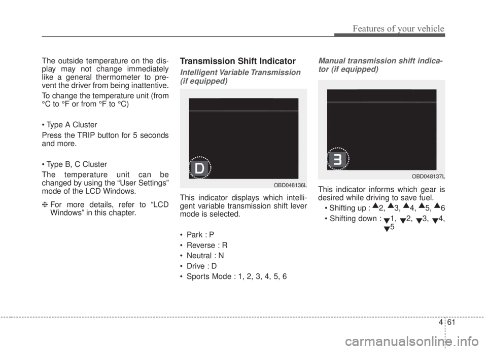
This indicator displays which intelli-
gent variable transmission shift lever
mode is selected.
Reverse : R
Neutral : N
Sports Mode : 1, 2, 3, 4, 5, 6
Manual transmission shift indica-tor (if equipped)
This indicator informs which gear is
desired while driving to save fuel.
▲
2, ▲
3, ▲
4, ▲
5, ▲
6
▼1,
▼2,
▼3,
▼4,
▼ 5OBD048136L
OBD048137L
Page 147 of 568

Features of your vehicle
62
4
For example
▲
3: Indicates that shifting up to the
3rd gear is desired (currently the
shift lever is in the 2nd or 1st
gear).
▼ 4: Indicates that shifting down to
the 4th gear is desired (currently
the shift lever is in the 5th or 6th
gear).
When the system is not working prop-
erly, the indicator is not displayed.Dual clutch transmission shift indicator (if equipped)
This indicator displays which shift
lever mode is selected.
Reverse : R
Neutral : N
Drive : D1, D2, D3, D4, D5, D6, D7
Sports Mode : S1, S2, S3, S4, S5, S6, S7
OBD048139L
Page 212 of 568

4127
Features of your vehicle
✽ ✽NOTICE
Never place anything over the sensor
located on the instrument panel to
ensure better control of the heating
and cooling system.
Manual heating and air condi-
tioning
The heating and cooling system can
be controlled manually by pressing
buttons or turning knob(s) other than
the AUTO button. In this case, the
system works sequentially according
to the order of buttons or knob(s)
selected.
1. Start the engine.
2. Set the mode to the desired posi-
tion.
For improving the effectiveness of
heating and cooling;- Heating:
- Cooling:
3. Set the temperature control to the desired position.
4. Set the air intake control to the outside (fresh) air position.
5. Set the fan speed control to the desired speed.
6. If air conditioning is desired, turn the air conditioning system on.
Press the AUTO button in order to
convert to full automatic control of
the system.
Mode selection
The mode selection button controls
the direction of the air flow through
the ventilation system.
The air flow outlet port is converted
as follows:
Refer to the illustration in the
“Manual climate control system”.
OBD048314
OBD048014
Page 214 of 568

4129
Features of your vehicle
Instrument panel vents- Type A
The outlet port can be opened or
closed separately using the horizon-
tal thumbwheel. To close the vent,
rotate it downward to the maximum
position. To open the vent, rotate it
upward to the desired position.
Also, you can adjust the direction of
air delivered from these vents using
the vent control lever as shown.
- Type B
The outlet vents can be opened or
closed separately turning the knob
right or left. Also, you can adjust the
direction of air delivery from these
vents by moving the knob in any
direction.
Temperature control
The temperature will increase to the
maximum (HI) by turning the knob all
the way to the right.
The temperature will decrease to the
minimum (Lo) by turning the knob all
the way to the left.
When turning the knob, the tempera-
ture will increase or decrease by
0.5°C/1°F. When set to the lowest
temperature increments setting, the
air conditioning will operate continu-
ously.
■Driver’s side■Passenger’s side
OBD048333
OBD048305
OBD048308
OBD048309
■Type B
■Type A
Page 232 of 568

4147
Features of your vehicle
* The actual sunvisor lamp in the vehi-cle may differ from the illustration.Sliding armrest (if equipped)
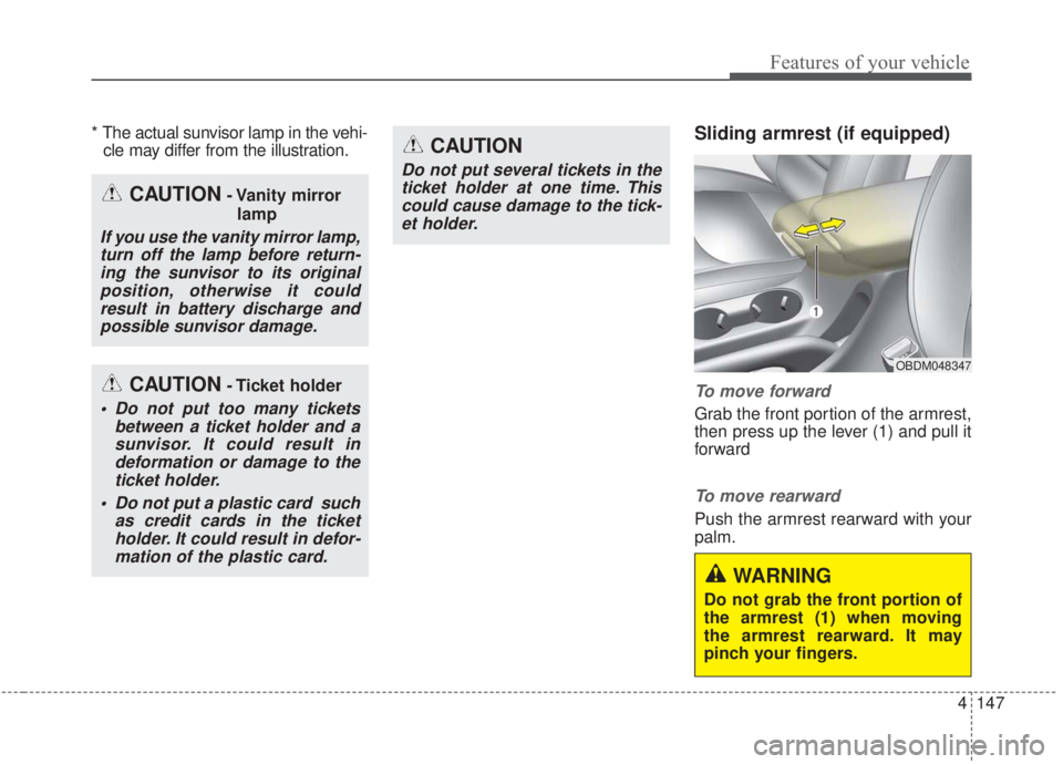
To move forward
Grab the front portion of the armrest,
then press up the lever (1) and pull it
forward
To move rearward
Push the armrest rearward with your
palm.
WARNING
Do not grab the front portion of
the armrest (1) when moving
the armrest rearward. It may
pinch your fingers.
OBDM048347
CAUTION- Vanity mirror
lamp
If you use the vanity mirror lamp,turn off the lamp before return-ing the sunvisor to its originalposition, otherwise it couldresult in battery discharge andpossible sunvisor damage.
CAUTION- Ticket holder
Do not put too many tickets between a ticket holder and asunvisor. It could result indeformation or damage to theticket holder.
Do not put a plastic card such as credit cards in the ticketholder. It could result in defor-mation of the plastic card.
CAUTION
Do not put several tickets in theticket holder at one time. Thiscould cause damage to the tick-et holder.
Page 234 of 568

4149
Features of your vehicle
USB charger (if equipped)
The USB car charger allows drivers
to charge their digital devices their
digital devices such as smartphones
and tablets. Connect the device to
the USB port using a manufacturer
certified cable to begin charging.
Power is supplied to the USB car
charger in either the ACC state or
with the ignition on. In order to pre-
vent battery discharge, only connect
digital devices to the USB port with
the ignition on. Use the display
screen of the connected device to
check its charging progress. Your
smartphone or tablet may heat up
while charging.This does not impact life or function
of the device. For safety reasons,
charging will stop if the battery heats
up to temperatures that will negative-
ly affect the device. Not all devices
are supported by the USB charger
and may require additional adapters.
CAUTION
- Use the USB car charger with
the ignition on. Otherwise,vehicle battery discharge mayoccur.
- Use a manufacturer certified USB cable compatible with thedigital device to be charged.
- Make sure that any foreign object, drinks, and water donot come into contact with theUSB car charger. Water or for-eign objects can damage theUSB charger.
- Do not connect devices with current consumption exceed-ing 2.1A.
- Do not connect devices that generate excessive electro-magnetic noise. Doing so mayinterrupt the vehicle audio/AVelectronic devices.
(Continued)
OBDM048083
Page 235 of 568

Features of your vehicle
150
4
Wireless smart phone charg-
ing system (if equipped)
The wireless smart phone charging
system is located in front of the cen-
ter console.
Firmly close all doors, and turn the
ignition to ACC or IGN ON. To start
wireless charging, place the smart
phone equipped with wireless charg-
ing function on the wireless charging
pad. For best wireless charging results,
place the smart phone on the center
of the charging pad.
The wireless charging system is
designed for single usage with smart
phones equipped with QI. Please
refer to the smart phone accessory
cover or the smart phone manufac-
turer homepage to check whether
your smart phone supports QI func-
tion.
OBD048404WARNING
If any metallic object such as a
coin is located between the
wireless charging system and
the smart phone, the charging
may be disrupted. Also, the
metallic object may heat up and
potentially damage the charg-
ing system.
(Continued)
- Ensure the devices are cor- rectly connected, failing to doso may cause serious damageto the device. Please note thatdamages due to incorrectusage are not covered by war-ranty service.