display KIA FORTE 2020 Workshop Manual
[x] Cancel search | Manufacturer: KIA, Model Year: 2020, Model line: FORTE, Model: KIA FORTE 2020Pages: 568, PDF Size: 8.58 MB
Page 374 of 568
Driving your vehicle
128
5
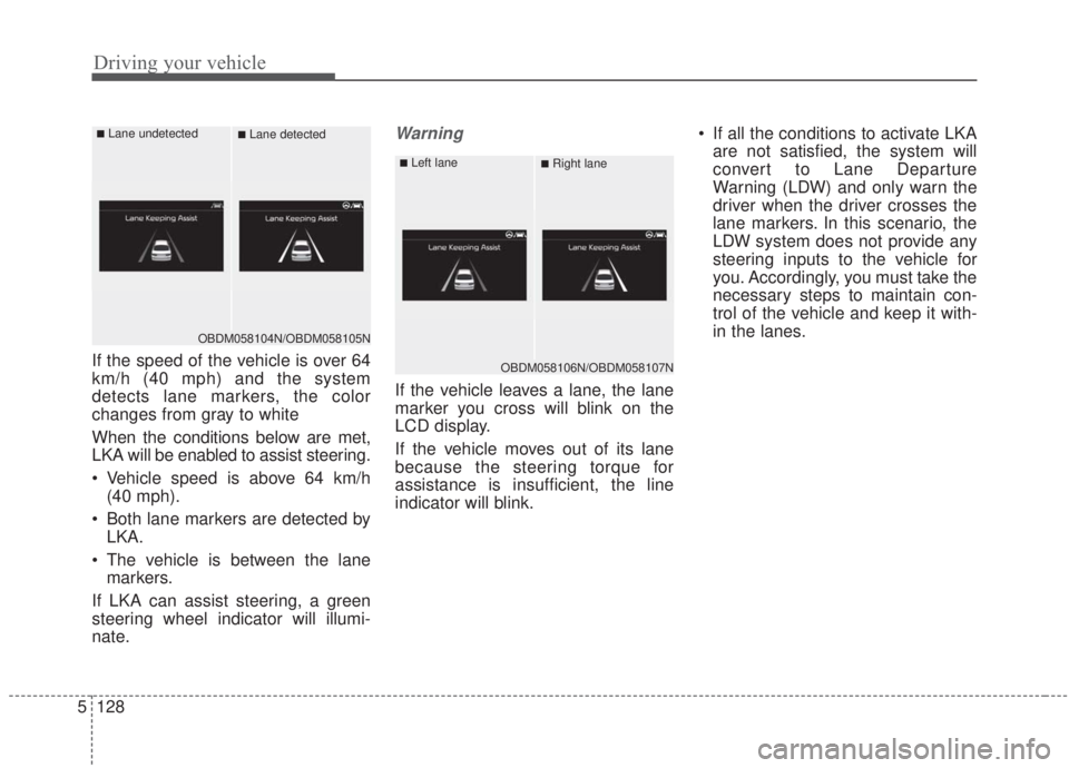
If the speed of the vehicle is over 64
km/h (40 mph) and the system
detects lane markers, the color
changes from gray to white
When the conditions below are met,
LKA will be enabled to assist steering.
Vehicle speed is above 64 km/h
(40 mph).
Both lane markers are detected by LKA.
The vehicle is between the lane markers.
If LKA can assist steering, a green
steering wheel indicator will illumi-
nate.
Warning
If the vehicle leaves a lane, the lane
marker you cross will blink on the
LCD display.
If the vehicle moves out of its lane
because the steering torque for
assistance is insufficient, the line
indicator will blink. If all the conditions to activate LKA
are not satisfied, the system will
convert to Lane Departure
Warning (LDW) and only warn the
driver when the driver crosses the
lane markers. In this scenario, the
LDW system does not provide any
steering inputs to the vehicle for
you. Accordingly, you must take the
necessary steps to maintain con-
trol of the vehicle and keep it with-
in the lanes.
OBDM058104N/OBDM058105N
■Lane undetected■Lane detected
OBDM058106N/OBDM058107N
■Left lane■Right lane
Page 379 of 568
5133
Driving your vehicle
When there is a problem with the sys-
tem, do one of the following:
Turn the system on after turningthe engine off and on again.
Check if the ignition switch is in the ON position.
Check if the system is affected by the weather. (ex: fog, heavy rain,
etc.)
Check if there is foreign matter on the camera lens
If the problem is not solved, take your
vehicle to an authorized Kia dealer
and have the system checked.LKA function change
The driver can change LKA to Lane
Departure Warning (LDW) system or
change the LKA mode between
Standard LKA and Active LKA from
the User Settings Mode on the LCD
display. The driver can choose the mode by
placing the ignition switch to the ON
position and by selecting ‘User
Settings’, ‘Driver Assistance’, and
‘Lane Safety’.
The system is automatically set to
Standard LKA when your vehicle is
first delivered from the factory.
Lane Departure Warning
LDW alerts the driver with a visual
and acoustic warning when the sys-
tem detects the vehicle leaving the
lane. In this mode, the system will not
provide steering inputs. When the
vehicle’s front wheel contacts the
inside edge of the lane, LKA issues
the lane departure warning.
Standard LKA
The Standard LKA mode guides the
driver to keep the vehicle within the
lanes. It provides inputs to the steer-
ing when the vehicle is about to devi-
ate from the lanes.
Active LKA
The active LKA mode provides more
frequent steering wheel control in
comparison with the Standard LKA
mode. Active LKA can reduce the dri-
ver’s fatigue by assisting the steering
to help maintain the vehicle in the
middle of the lane.
Page 380 of 568
Driving your vehicle
134
5
The Driver Attention Warning (DAW)
system is designed to warn the driv-
er of potentially hazardous driving
situations if it detects inattentive
driving practices.System setting and activation
System setting
The Driver Attention Warning sys-
tem is set to be the Normal posi-
tion when your vehicle is first deliv-
ered to you from the factory.
To turn ON the Driver Attention Warning system, turn on the
engine and then select 'User
Settings →Driver Assistance →
DAW (Driver Attention Warning) →
High sensitivity/Normal sensitivi-
ty/Off' on the LCD display. The driver can select the Driver
Attention Warning system mode.
- Off : The Driver Attention Warningsystem is deactivated.
- Normal sensitivity : The Driver Attention Warning system alerts
the driver of his/her fatigue level
or inattentive driving practices.
- High sensitivity : The Driver Attention Warning system alerts
the driver of his/her fatigue level
or inattentive driving practices
faster than Normal mode.
The Driver Attention Warning sys- tem mode will be maintained, as
selected, when the engine is
restarted.
DRIVER ATTENTION WARNING (DAW, IF EQUIPPED)
Page 381 of 568
5135
Driving your vehicle
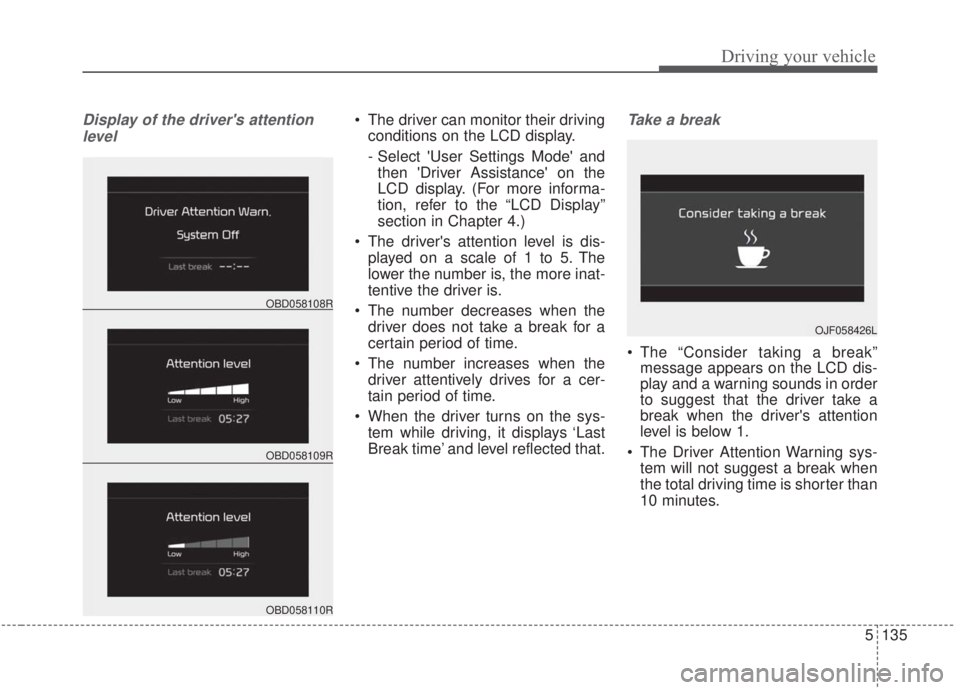
Display of the driver's attentionlevel The driver can monitor their driving conditions on the LCD display.
- Select 'User Settings Mode' andthen 'Driver Assistance' on the
LCD display. (For more informa-
tion, refer to the “LCD Display”
section in Chapter 4.)
The driver's attention level is dis- played on a scale of 1 to 5. The
lower the number is, the more inat-
tentive the driver is.
The number decreases when the driver does not take a break for a
certain period of time.
The number increases when the driver attentively drives for a cer-
tain period of time.
When the driver turns on the sys- tem while driving, it displays ‘Last
Break time’ and level reflected that.Take a break
The “Consider taking a break”message appears on the LCD dis-
play and a warning sounds in order
to suggest that the driver take a
break when the driver's attention
level is below 1.
The Driver Attention Warning sys- tem will not suggest a break when
the total driving time is shorter than
10 minutes.
OBD058109R
OBD058108R
OBD058110R
OJF058426L
Page 382 of 568

Driving your vehicle
136
5
Resetting the system
The last break time is set to 00:00
and the driver's attention level is
set to 5 (very attentive) when the
driver resets the Driver Attention
Warning system.
The driver attention warning sys- tem resets in the following situa-
tions. - The engine is turned OFF.
- The driver unfastens the seat belt
and then opens the driver’s door
when stopped.
- The driver takes a break from driving that lasts more than 10
minutes.
The driver attention warning sys- tem will operate again when the
driver restarts driving.
System disabled
The Driver Attention Warning system
enters the ready status and displays
the 'Disabled' screen in the following
situations.
- The camera sensor is unable todetect the lanes.
- Driving speed remains under 64 km/h (40 mph) or over 177 km/h
(110 mph).
OBD058114R
Page 407 of 568
What to do in an emergency
86
TIRE PRESSURE MONITORING SYSTEM (TPMS)
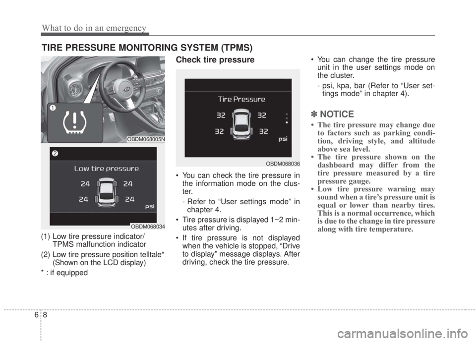
(1) Low tire pressure indicator/TPMS malfunction indicator
(2) Low tire pressure position telltale* (Shown on the LCD display)
* : if equipped
Check tire pressure
You can check the tire pressure in the information mode on the clus-
ter.
- Refer to “User settings mode” inchapter 4.
Tire pressure is displayed 1~2 min- utes after driving.
If tire pressure is not displayed when the vehicle is stopped, “Drive
to display” message displays. After
driving, check the tire pressure. You can change the tire pressure
unit in the user settings mode on
the cluster.
- psi, kpa, bar (Refer to “User set-tings mode” in chapter 4).
✽ ✽ NOTICE
• The tire pressure may change due
to factors such as parking condi-
tion, driving style, and altitude
above sea level.
• The tire pressure shown on the dashboard may differ from the
tire pressure measured by a tire
pressure gauge.
• Low tire pressure warning may sound when a tire’s pressure unit is
equal or lower than nearby tires.
This is a normal occurrence, which
is due to the change in tire pressure
along with tire temperature.
OBDM068005N
OBDM068034
OBDM068036
Page 425 of 568
What to do in an emergency
26
6
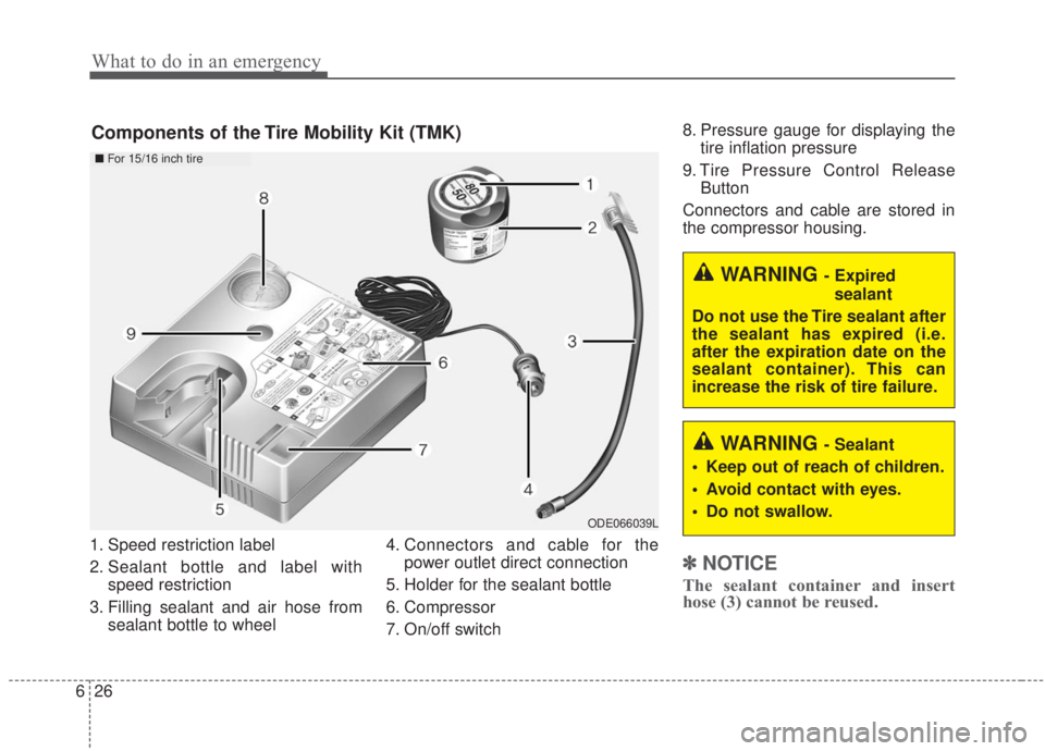
1. Speed restriction label
2. Sealant bottle and label with
speed restriction
3. Filling sealant and air hose from sealant bottle to wheel 4. Connectors and cable for the
power outlet direct connection
5. Holder for the sealant bottle
6. Compressor
7. On/off switch 8. Pressure gauge for displaying the
tire inflation pressure
9. Tire Pressure Control Release Button
Connectors and cable are stored in
the compressor housing.
✽ ✽ NOTICE
The sealant container and insert
hose (3) cannot be reused.
ODE066039L
Components of the Tire Mobility Kit (TMK)
WARNING - Sealant
Keep out of reach of children.
Avoid contact with eyes.
Do not swallow.
WARNING - Expired sealant
Do not use the Tire sealant after
the sealant has expired (i.e.
after the expiration date on the
sealant container). This can
increase the risk of tire failure.
■ For 15/16 inch tire
Page 426 of 568
627
What to do in an emergency
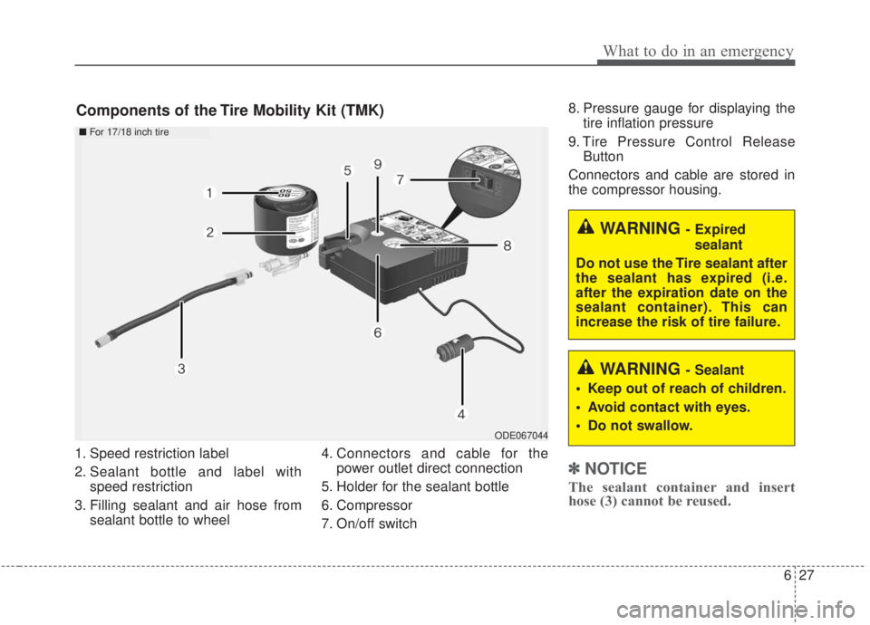
1. Speed restriction label
2. Sealant bottle and label withspeed restriction
3. Filling sealant and air hose from sealant bottle to wheel 4. Connectors and cable for the
power outlet direct connection
5. Holder for the sealant bottle
6. Compressor
7. On/off switch 8. Pressure gauge for displaying the
tire inflation pressure
9. Tire Pressure Control Release Button
Connectors and cable are stored in
the compressor housing.
✽ ✽ NOTICE
The sealant container and insert
hose (3) cannot be reused.
Components of the Tire Mobility Kit (TMK)
ODE067044
■ For 17/18 inch tire
WARNING - Sealant
Keep out of reach of children.
Avoid contact with eyes.
Do not swallow.
WARNING - Expired sealant
Do not use the Tire sealant after
the sealant has expired (i.e.
after the expiration date on the
sealant container). This can
increase the risk of tire failure.
Page 490 of 568
753
Maintenance
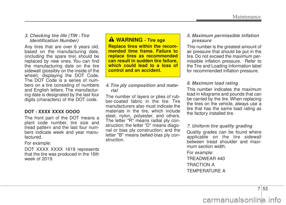
3. Checking tire life (TIN : TireIdentification Number)
Any tires that are over 6 years old,
based on the manufacturing date,
(including the spare tire) should be
replaced by new ones. You can find
the manufacturing date on the tire
sidewall (possibly on the inside of the
wheel), displaying the DOT Code.
The DOT Code is a series of num-
bers on a tire consisting of numbers
and English letters. The manufactur-
ing date is designated by the last four
digits (characters) of the DOT code.
DOT : XXXX XXXX OOOO
The front part of the DOT means a
plant code number, tire size and
tread pattern and the last four num-
bers indicate week and year manu-
factured.
For example:
DOT XXXX XXXX 1619 represents
that the tire was produced in the 16th
week of 2019.
4. Tire ply composition and mate-rial
The number of layers or plies of rub-
ber-coated fabric in the tire. Tire
manufacturers also must indicate the
materials in the tire, which include
steel, nylon, polyester, and others.
The letter "R" means radial ply con-
struction; the letter "D" means diago-
nal or bias ply construction; and the
letter "B" means belted-bias ply con-
struction.
5. Maximum permissible inflationpressure
This number is the greatest amount of
air pressure that should be put in the
tire. Do not exceed the maximum per-
missible inflation pressure. Refer to
the Tire and Loading Information label
for recommended inflation pressure.
6. Maximum load rating
This number indicates the maximum
load in kilograms and pounds that can
be carried by the tire. When replacing
the tires on the vehicle, always use a
tire that has the same load rating as
the factory installed tire.
7. Uniform tire quality grading
Quality grades can be found where
applicable on the tire sidewall
between tread shoulder and maxi-
mum section width.
For example:
TREADWEAR 440
TRACTION A
TEMPERATURE A
WARNING - Tire age
Replace tires within the recom-
mended time frame. Failure to
replace tires as recommended
can result in sudden tire failure,
which could lead to a loss of
control and an accident.
Page 500 of 568
763
Maintenance
✽ ✽NOTICE- Remodeling
Prohibited
Do not rewire your vehicle in any
way as doing so may affect the per-
formance of several safety features
in your vehicle. Rewiring your vehi-
cle may also void your warranty and
cause you to be responsible for any
subsequent vehicle damage which
may result.
✽ ✽ NOTICE- Window tinting pre-
caution
Window tint (especially metallic
film) might cause communication
errors or poor radio reception, and a
malfunctioning automatic lighting
system due to reflections from the
mirror tint inside the vehicle. The
tint installation solution used might
also leak into the electronic compo-
nents, causing malfunctions or dam-
age.
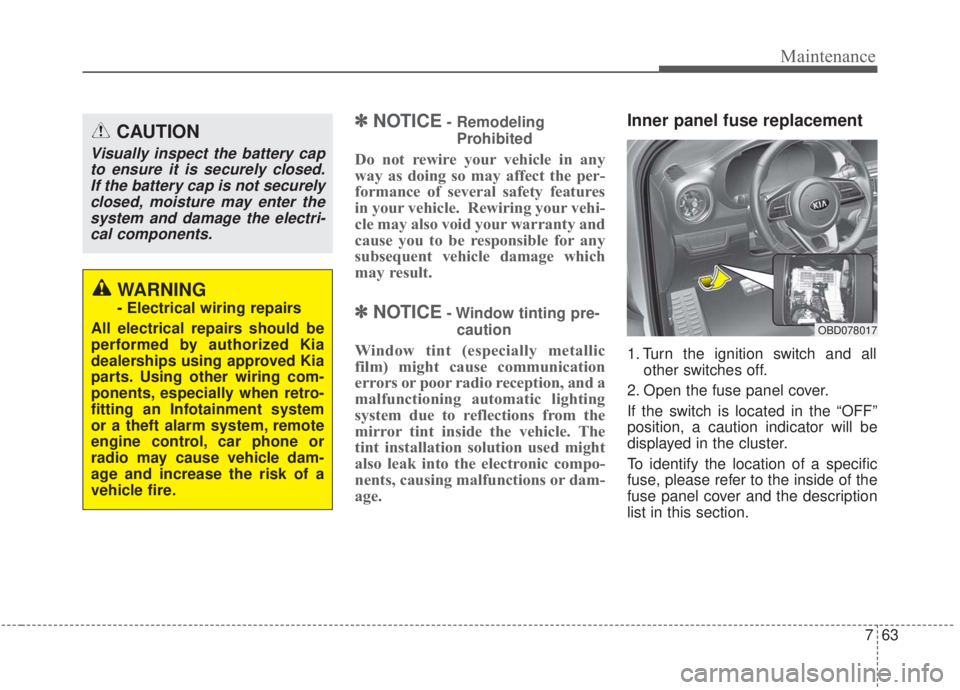
Inner panel fuse replacement
1. Turn the ignition switch and all other switches off.
2. Open the fuse panel cover.
If the switch is located in the “OFF”
position, a caution indicator will be
displayed in the cluster.
To identify the location of a specific
fuse, please refer to the inside of the
fuse panel cover and the description
list in this section.
CAUTION
Visually inspect the battery cap to ensure it is securely closed.If the battery cap is not securelyclosed, moisture may enter thesystem and damage the electri-cal components.
WARNING
- Electrical wiring repairs
All electrical repairs should be
performed by authorized Kia
dealerships using approved Kia
parts. Using other wiring com-
ponents, especially when retro-
fitting an Infotainment system
or a theft alarm system, remote
engine control, car phone or
radio may cause vehicle dam-
age and increase the risk of a
vehicle fire.
OBD078017