sensor KIA FORTE KOUP 2018 Owner's Guide
[x] Cancel search | Manufacturer: KIA, Model Year: 2018, Model line: FORTE KOUP, Model: KIA FORTE KOUP 2018Pages: 584, PDF Size: 15.16 MB
Page 421 of 584
Driving your vehicle
80
5
- A fixed object is near such as a
guardrail, etc.
- A substantial amount of metallic objects such as a construction
area.
- A large vehicle is nearby such as a bus or truck.
- A motorcycle or bicycle is near.
- A flat trailer is near.
- If two vehicles near each other accelerate together.
- When another vehicle passes by at a high rate of speed.
- When changing lanes.
- When going down or up a steep, uneven road.
- When another vehicle drives very close the back bumper/trunk.
- When a trailer or carrier is installed. - When the temperature of the rear
bumper is very high or low.
- When bike racks, etc. cover the sensor.
- When reversing from a parking space with pillars or metal struc-
tures.
- When you are reversing and if the detected vehicle is simultaneously
reversing.
- If there are small objects like shop- ping carts and baby carriages.
- If there is a vehicle with decreased ride height (lowered).
- When the vehicle is close to anoth- er vehicle.
- When driving through a narrow road with many plants.
- When driving on wet surface.Outside rearview mirror may not alert the driver when:
- The outside rearview mirror hous- ing is very dirty.
- The window is very dirty.
- The windows are tinted very dark.
- When driving through a narrow road with many plants.
Page 448 of 584
611
What to do in an emergency
Distributing the sealant
11. Immediately drive approximately7~10 km (4~6 miles or, about
10min) to evenly distribute the
sealant in the tire.
Do not exceed a speed of 80 km/h
(50 mph). If possible, do not fall
below a speed of 20 km/h (12 mph).
While driving, if you experience any
unusual vibration, ride disturbance or
noise, reduce your speed and drive
with caution until you can safely pull
off of the side of the road.
Call for road side service or towing.
When you use the Tire Mobility Kit,
the tire pressure sensors and wheel
may be stained by sealant.
Therefore, remove the tire pressure
sensors and wheel stained by
sealant and we recommend that
inspect at an authorized Kia dealer.
Checking the tire inflation
pressure
1.After driving approximately 7 ~ 10 km (4 ~ 6 miles or about 10 min),
stop at a safe location.
2.Connect connection hose (9) of the compressor directly to the tire
valve.
3.Plug the compressor power cord into the vehicle power outlet.
4.Adjust the tire inflation pressure to the recomended tire inflation.
With the ignition switch on, pro-
ceed as follows.
- To increase the inflation pres-sure : Switch on the compressor,
position I. To check the current
inflation pressure setting, briefly
switch off the compressor.
✽ ✽ NOTICE
The pressure gauge may show high-
er than actual reading when the
compressor is running. To get an
accurate tire reading, the compres-
sor needs to be turned off.
- To reduce the inflation pres-
sure: Press the button 8 on the
compressor.
Page 449 of 584
What to do in an emergency
12
6
Technical Data
System voltage : DC 12 V
Working voltage : DC 10 - 15 V
Amperage rating : max. 15 A
Suitable for use at temperatures :
-30 ~ +70°C (-22 ~ +158°F)
Max. working pressure : 6 bar (87 psi)
Size
Compressor : 168 x 150 x 68 mm (6.6 x 5.9 x 2.7 in.)
Sealant bottle : 104 x ø 85 mm (4.1 x ø 3.3 in.)
Compressor weight : 1.05 kg (2.31 lbs)
Sealant volume : 300 ml (18.3 cu. in.)
Sealant warranty : 5 years (sealant.)CAUTION - Tire pressuresensor
When you use the Tire Mobility
Kit including sealant notapproved by Kia, the tire pres-sure sensors may be damagedby sealant. The sealant on thetire pressure sensor and wheelshould be removed when youreplace the tire with a new oneand inspect the tire pressuresensors at an authorized dealer.
Page 459 of 584
What to do in an emergency
22
6
TOWING
Towing service
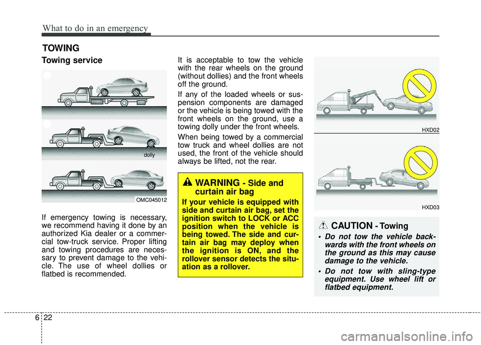
If emergency towing is necessary,
we recommend having it done by an
authorized Kia dealer or a commer-
cial tow-truck service. Proper lifting
and towing procedures are neces-
sary to prevent damage to the vehi-
cle. The use of wheel dollies or
flatbed is recommended. It is acceptable to tow the vehicle
with the rear wheels on the ground
(without dollies) and the front wheels
off the ground.
If any of the loaded wheels or sus-
pension components are damaged
or the vehicle is being towed with the
front wheels on the ground, use a
towing dolly under the front wheels.
When being towed by a commercial
tow truck and wheel dollies are not
used, the front of the vehicle should
always be lifted, not the rear.
CAUTION- Towing
Do not tow the vehicle back-
wards with the front wheels onthe ground as this may causedamage to the vehicle.
Do not tow with sling-type equipment. Use wheel lift orflatbed equipment.
OMC045012
dolly
HXD02
HXD03
WARNING - Side and
curtain air bag
If your vehicle is equipped with
side and curtain air bag, set the
ignition switch to LOCK or ACC
position when the vehicle is
being towed. The side and cur-
tain air bag may deploy when
the ignition is ON, and the
rollover sensor detects the situ-
ation as a rollover.
Page 503 of 584
741
Maintenance
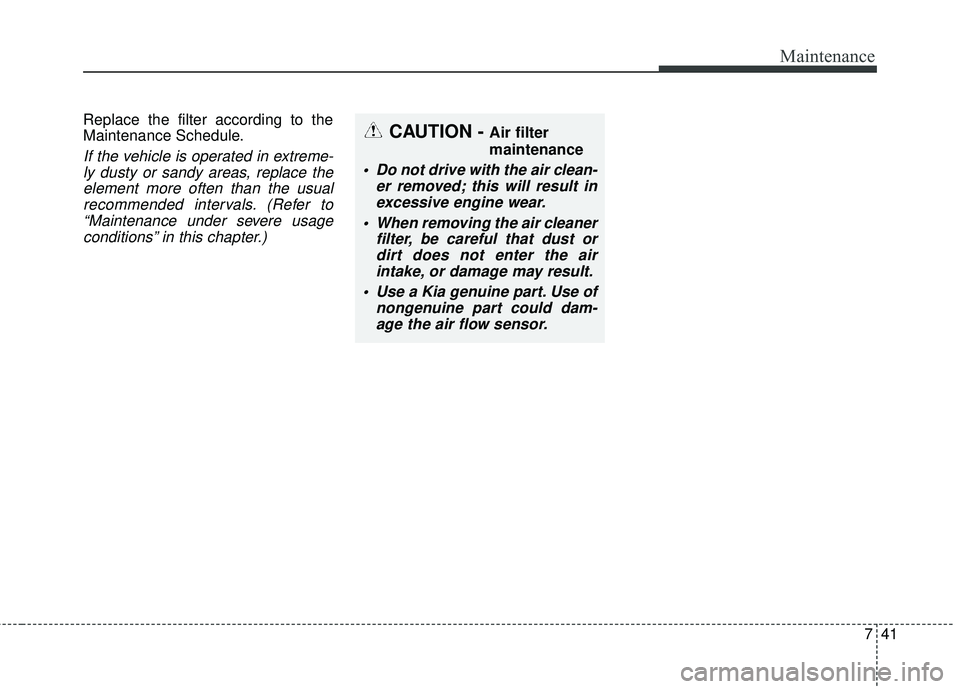
Replace the filter according to the
Maintenance Schedule.
If the vehicle is operated in extreme-ly dusty or sandy areas, replace theelement more often than the usualrecommended intervals. (Refer to“Maintenance under severe usageconditions” in this chapter.)
CAUTION - Air filter
maintenance
Do not drive with the air clean- er removed; this will result inexcessive engine wear.
When removing the air cleaner filter, be careful that dust ordirt does not enter the airintake, or damage may result.
Use a Kia genuine part. Use of nongenuine part could dam-age the air flow sensor.
Page 535 of 584
773
Maintenance
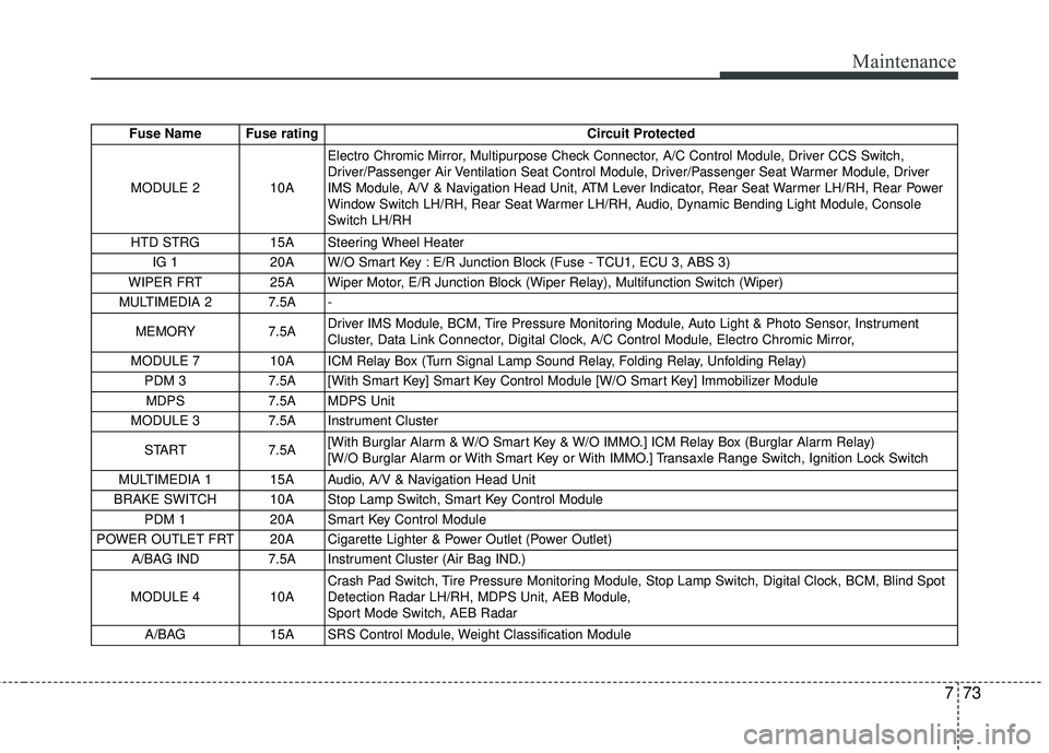
Fuse Name Fuse ratingCircuit Protected
MODULE 2 10A Electro Chromic Mirror, Multipurpose Check Connector, A/C Control Module, Driver CCS Switch,
Driver/Passenger Air Ventilation Seat Control Module, Driver/Passenger Seat Warmer Module, Driver
IMS Module, A/V & Navigation Head Unit, ATM Lever Indicator, Rear Seat Warmer LH/RH, Rear Power
Window Switch LH/RH, Rear Seat Warmer LH/RH, Audio, Dynamic Bending Light Module, Console
Switch LH/RH
HTD STRG 15A Steering Wheel Heater
IG 1 20A W/O Smart Key : E/R Junction Block (Fuse - TCU1, ECU 3, ABS 3)
WIPER FRT 25A Wiper Motor, E/R Junction Block (Wiper Relay), Multifunction Switch (Wiper)
MULTIMEDIA 2 7.5A -
MEMORY 7.5ADriver IMS Module, BCM, Tire Pressure Monitoring Module, Auto Light & Photo Sensor, Instrument
Cluster, Data Link Connector, Digital Clock, A/C Control Module, Electro Chromic Mirror,
MODULE 7 10A ICM Relay Box (Turn Signal Lamp Sound Relay, Folding Relay, Unfolding Relay)
PDM 3 7.5A [With Smart Key] Smart Key Control Module [W/O Smart Key] Immobilizer Module
MDPS 7.5A MDPS Unit
MODULE 3 7.5A Instrument Cluster
START 7.5A[With Burglar Alarm & W/O Smart Key & W/O IMMO.] ICM Relay Box (Burglar Alarm Relay)
[W/O Burglar Alarm or With Smart Key or With IMMO.] Transaxle Range Switch, Ignition Lock Switch
MULTIMEDIA 1 15A Audio, A/V & Navigation Head Unit
BRAKE SWITCH 10A Stop Lamp Switch, Smart Key Control Module PDM 1 20A Smart Key Control Module
POWER OUTLET FRT 20A Cigarette Lighter & Power Outlet (Power Outlet) A/BAG IND 7.5A Instrument Cluster (Air Bag IND.)
MODULE 4 10ACrash Pad Switch, Tire Pressure Monitoring Module, Stop Lamp Switch, Digital Clock, BCM, Blind Spot
Detection Radar LH/RH, MDPS Unit, AEB Module,
Sport Mode Switch, AEB Radar
A/BAG 15A SRS Control Module, Weight Classification Module
Page 539 of 584
777
Maintenance
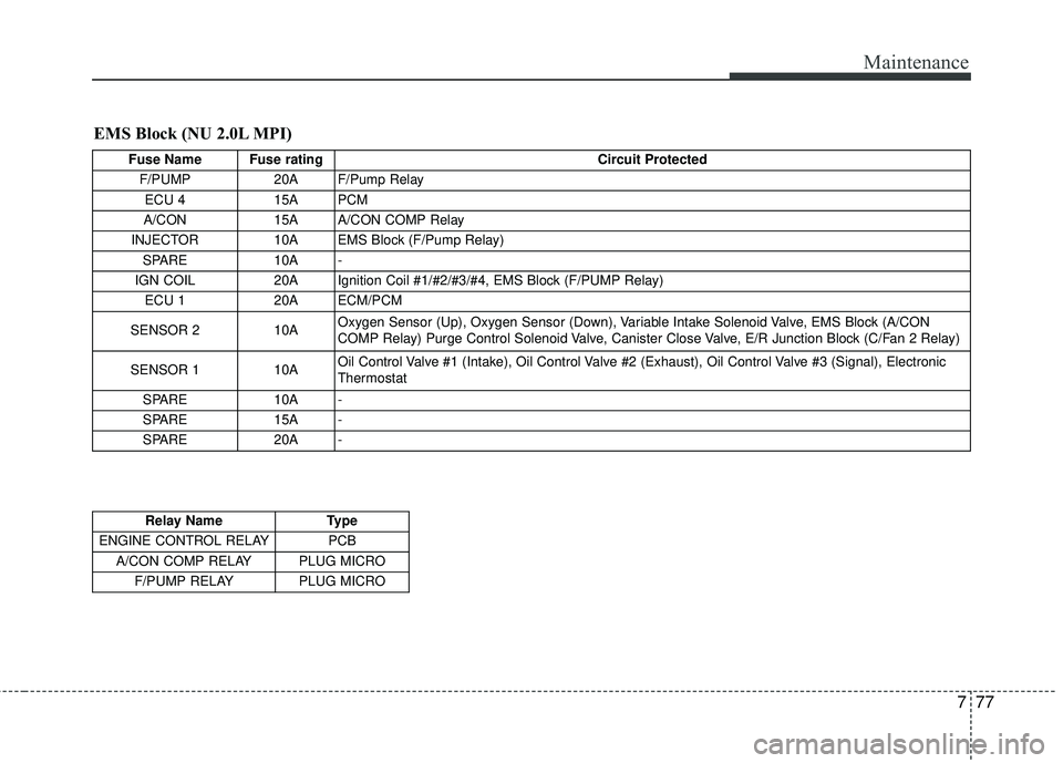
EMS Block (NU 2.0L MPI)
Fuse Name Fuse ratingCircuit Protected
F/PUMP 20A F/Pump Relay
ECU 4 15A PCM
A/CON 15A A/CON COMP Relay
INJECTOR 10A EMS Block (F/Pump Relay)
SPARE 10A -
IGN COIL 20A Ignition Coil #1/#2/#3/#4, EMS Block (F/PUMP Relay)
ECU 1 20A ECM/PCM
SENSOR 2 10A Oxygen Sensor (Up), Oxygen Sensor (Down), Variable Intake Solenoid Valve, EMS Block (A/CON
COMP Relay) Purge Control Solenoid Valve, Canister Close Valve, E/R Junction Block (C/Fan 2 Relay)
SENSOR 1 10A Oil Control Valve #1 (Intake), Oil Control Valve #2 (Exhaust), Oil Control Valve #3 (Signal), Electronic
Thermostat
SPARE 10A -
SPARE 15A -
SPARE 20A -
Relay Name Type
ENGINE CONTROL RELAY PCB A/CON COMP RELAY PLUG MICRO F/PUMP RELAY PLUG MICRO
Page 540 of 584
Maintenance
78
7
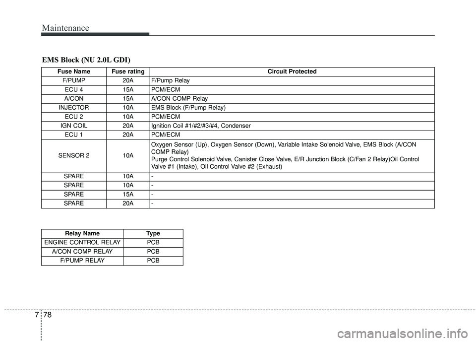
EMS Block (NU 2.0L GDI)
Fuse Name Fuse rating Circuit Protected
F/PUMP 20A F/Pump Relay
ECU 4 15A PCM/ECM
A/CON 15A A/CON COMP Relay
INJECTOR 10A EMS Block (F/Pump Relay)
ECU 2 10A PCM/ECM
IGN COIL 20A Ignition Coil #1/#2/#3/#4, Condenser
ECU 1 20A PCM/ECM
SENSOR 2 10A Oxygen Sensor (Up), Oxygen Sensor (Down), Variable Intake Solenoid Valve, EMS Block (A/CON
COMP Relay)
Purge Control Solenoid Valve, Canister Close Valve, E/R Junction Block (C/Fan 2 Relay)Oil Control
Valve #1 (Intake), Oil Control Valve #2 (Exhaust)
SPARE 10A -
SPARE 10A -
SPARE 15A -
SPARE 20A -
Relay Name Type
ENGINE CONTROL RELAY PCB A/CON COMP RELAY PCB
F/PUMP RELAY PCB
Page 541 of 584
779
Maintenance
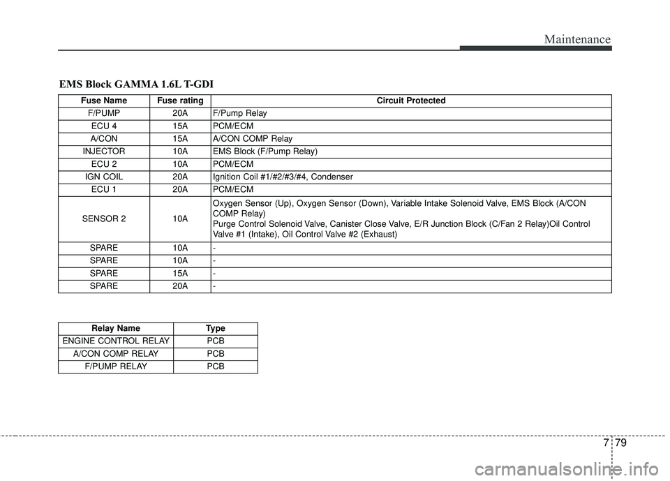
EMS Block GAMMA 1.6L T-GDI
Fuse Name Fuse ratingCircuit Protected
F/PUMP 20A F/Pump Relay
ECU 4 15A PCM/ECM
A/CON 15A A/CON COMP Relay
INJECTOR 10A EMS Block (F/Pump Relay)
ECU 2 10A PCM/ECM
IGN COIL 20A Ignition Coil #1/#2/#3/#4, Condenser
ECU 1 20A PCM/ECM
SENSOR 2 10A Oxygen Sensor (Up), Oxygen Sensor (Down), Variable Intake Solenoid Valve, EMS Block (A/CON
COMP Relay)
Purge Control Solenoid Valve, Canister Close Valve, E/R Junction Block (C/Fan 2 Relay)Oil Control
Valve #1 (Intake), Oil Control Valve #2 (Exhaust)
SPARE 10A -
SPARE 10A -
SPARE 15A -
SPARE 20A -
Relay Name Type
ENGINE CONTROL RELAY PCB A/CON COMP RELAY PCB
F/PUMP RELAY PCB
Page 556 of 584
Maintenance
94
7
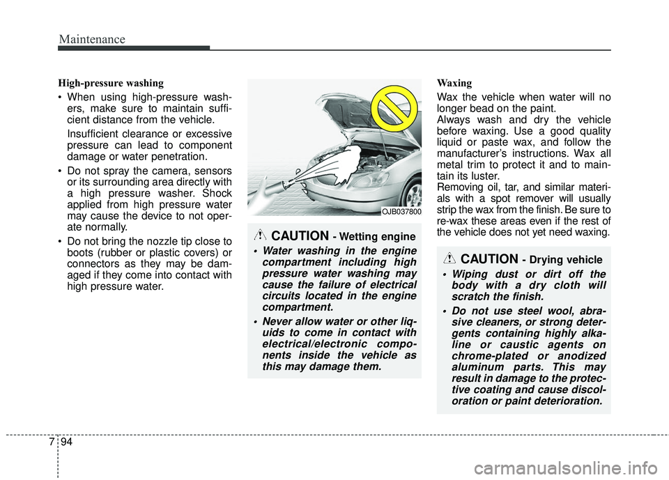
High-pressure washing
When using high-pressure wash-
ers, make sure to maintain suffi-
cient distance from the vehicle.
Insufficient clearance or excessive
pressure can lead to component
damage or water penetration.
Do not spray the camera, sensors or its surrounding area directly with
a high pressure washer. Shock
applied from high pressure water
may cause the device to not oper-
ate normally.
Do not bring the nozzle tip close to boots (rubber or plastic covers) or
connectors as they may be dam-
aged if they come into contact with
high pressure water. Waxing
Wax the vehicle when water will no
longer bead on the paint.
Always wash and dry the vehicle
before waxing. Use a good quality
liquid or paste wax, and follow the
manufacturer’s instructions. Wax all
metal trim to protect it and to main-
tain its luster.
Removing oil, tar, and similar materi-
als with a spot remover will usually
strip the wax from the finish. Be sure to
re-wax these areas even if the rest of
the vehicle does not yet need waxing.
CAUTION - Wetting engine
Water washing in the engine
compartment including highpressure water washing maycause the failure of electricalcircuits located in the enginecompartment.
Never allow water or other liq- uids to come in contact withelectrical/electronic compo-nents inside the vehicle asthis may damage them.
OJB037800
CAUTION - Drying vehicle
Wiping dust or dirt off the body with a dry cloth willscratch the finish.
Do not use steel wool, abra- sive cleaners, or strong deter-gents containing highly alka-line or caustic agents onchrome-plated or anodizedaluminum parts. This mayresult in damage to the protec-tive coating and cause discol-oration or paint deterioration.