instrument panel KIA NIRO PHEV 2020 User Guide
[x] Cancel search | Manufacturer: KIA, Model Year: 2020, Model line: NIRO PHEV, Model: KIA NIRO PHEV 2020Pages: 687, PDF Size: 11.43 MB
Page 129 of 687

365
Safety features of your vehicle
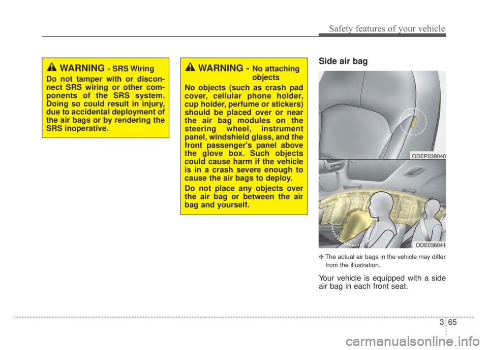
Side air bag
❈The actual air bags in the vehicle may differ
from the illustration.
Your vehicle is equipped with a side
air bag in each front seat.
WARNING- SRS Wiring
Do not tamper with or discon-
nect SRS wiring or other com-
ponents of the SRS system.
Doing so could result in injury,
due to accidental deployment of
the air bags or by rendering the
SRS inoperative.WARNING - No attaching
objects
No objects (such as crash pad
cover, cellular phone holder,
cup holder, perfume or stickers)
should be placed over or near
the air bag modules on the
steering wheel, instrument
panel, windshield glass, and the
front passenger's panel above
the glove box. Such objects
could cause harm if the vehicle
is in a crash severe enough to
cause the air bags to deploy.
Do not place any objects over
the air bag or between the air
bag and yourself.
ODE036041
ODEP039040
Page 185 of 687

Features of your vehicle
48
4
(Continued)
• When the charging system warning
light comes on due to low voltage
(when the alternator or battery
does not operate normally or mal-
function), the steering wheel may
require increased steering effort.Tilt and telescopic steering
Tilt and telescopic steering allows
you to adjust the steering wheel
before you drive. You can also raise it
to give your legs more space when
you get on or off the vehicle.
The steering wheel should be posi-
tioned so that it is comfortable for
you to drive, while permitting you to
see the instrument panel warning
lights and gauges. To change the steering wheel angle,
pull down the lock-release lever (1),
adjust the steering wheel to the
desired angle (2) and height (3) then
pull up the lock-release lever to lock
(4) the steering wheel in place. Be
sure to adjust the steering wheel to
the desired position before driving.
✽ ✽NOTICE
After adjustment, sometimes the
lock release lever may not lock the
steering wheel. It is not a malfunc-
tion. This occurs when two gears are
not engaged correctly. In this case,
adjust the steering wheel again and
then lock the steering wheel.
WARNING- Steering
wheel adjustment
Never adjust the angle and
height of the steering wheel
while driving. You may lose
steering control.
ODE046022
Page 196 of 687

459
Features of your vehicle
Instrument Cluster Control
Adjusting Instrument ClusterIllumination
The brightness of the instrument
panel illumination is changed by
pressing the illumination control but-
ton (“+” or “-”) when the ignition
switch or ENGINE START/STOP but-
ton is ON, or the taillights are turned
on. If you hold the illumination control
button (“+” or “-”), the brightness
will be changed continuously.
If the brightness reaches to the maximum or minimum level, an
alarm will sound.
Gauges
Speedometer
The speedometer indicates the
speed of the vehicle and is calibrated
in miles per hour (mph) and/or kilo-
meters per hour (km/h).
ODEP049545L
ODEP049543L
ODEP049105N
ODEP049539N
■
Type A
■Type B
Page 227 of 687

Features of your vehicle
90
4
Device in wireless charger
(if equipped)
If a smart phone is still left on the wire-
less charging pad unattended, even
when the ENGINE START/STOP but-
ton is turned to the ACC or OFF posi-
tion. And the instrument panel's one
time driving information mode has fin-
ished, a warning message will lit up on
the instrument panel.
❈ For more details, refer to “Wireless
smart phone charging system” in
this chapter.
Check Hybrid system
This warning message illuminates
when there is a problem with the
hybrid control system.
Refrain from driving when the warn-
ing message is displayed.
In this case, have your vehicle inspect-
ed by an authorized Kia dealer.
Check Hybrid system. Turn
engine off
This warning message illuminates
when there is a problem with the
hybrid system. The “ ” indicator
will blink and a warning chime will
sound until the problem is solved.
In this case, have your vehicle inspect-
ed by an authorized Kia dealer.
Check Hybrid system. Do not startengine
This warning message illuminates
when the hybrid battery power
(SOC) level is low. A warning chime
will sound until the problem is solved.
In this case, have your vehicle inspect-
ed by an authorized Kia dealer.
Stop vehicle and check powersupply
This warning message illuminates
when a failure occurs in the power
supply system.
In this case, park the vehicle in a
safe location and tow your vehicle to
the nearest authorized Kia dealer
and have the vehicle inspected.
Page 253 of 687

Features of your vehicle
116
4
Lighting control
The light switch has a Headlight and
a Parking light position.
To operate the lights, turn the knob at
the end of the control lever to one of
the following positions:
(1) OFF position
(2) Auto light position
(3) Parking & Tail light
(4) Headlight position
Parking & Tail light ( )
When the light switch is in the park-
ing light position, the tail, license and
instrument panel lights will turn ON.
Headlight position ( )
When the light switch is in the head-
light position, the head, tail, license
lights will turn ON.
✽ ✽
NOTICE
The ignition switch must be in the ON
position to turn on the headlights.
OUM044055 OUMA046056 OUMA046054
Page 254 of 687

4117
Features of your vehicle
Auto light position
When the light switch is in the AUTO
light position, the taillights and head-
lights will turn ON or OFF automati-
cally depending on the amount of
light outside the vehicle.
When the light switch is positioned at
an auto light position, at first, the
wiper will turn on and then, after 5
seconds the head lamp will turn on
automatically.
If the head lamp has been turned on
due to this function of the vehicle, the
head lamp will turn off 60 seconds
after the wiper has been turned off.
High beam operation
To turn on the high beam headlamp,
push the lever away from you. The
lever will return to its original position.
The high beam indicator will light
when the headlight high beams are
switched on.
To prevent the battery from being
discharged, do not leave the lights
on for a prolonged time while the
engine is not running.
ODEP049408NOUM044059
CAUTION
Never place anything over thesensor (1) located on theinstrument panel as this willensure better auto-light sys-tem control.
Don’t clean the sensor using a window cleaner, the cleanermay leave a light film whichcould interfere with sensoroperation.
If your vehicle has window tint or other types of metallic coat-ing on the front windshield,the Auto light system may notwork properly.
Page 257 of 687

Features of your vehicle
120
4
When driving downhill or uphill.
When only part of the vehicle in
front is visible on a crossroad or
curved road.
When there is a traffic light, reflect- ing sign, flashing sign or mirror.
When the road conditions are bad such as being wet or covered with
snow.
When the front vehicle’s head- lamps are off but the fog lamps on.
When a vehicle suddenly appears from a curve.
When the vehicle is tilted from a flat tire or being towed.
When the Lane Keeping Assist system warning light illuminates. (if
equipped)✽ ✽ NOTICE
• Do not place any accessories,
stickers or tint the windshield.
• Have the windshield glass replaced from an authorized dealer.
• Do not remove or damage related parts of High Beam Assist system.
• Be careful that water doesn’t get into the High Beam Assist unit.
• Do not place objects on the dash- board that reflect light such as
mirrors, white paper, etc. The sys-
tem may malfunction if sunlight is
reflected.
• At times, High Beam Assist sys- tem may not work properly,
always check the road conditions
for your safety. When the system
does not operate normally, manu-
ally change between the high
beam and low beam.
Turn signals and lane change
signals
The ignition switch must be on for the
turn signals to function. To turn on
the turn signals, move the lever up or
down (A). The green arrow indicators
on the instrument panel indicate
which turn signal is operating.
They will self-cancel after a turn is
completed. If the indicator continues
to flash after a turn, manually return
the lever to the OFF position.
To signal a lane change, move the
turn signal lever slightly and hold it in
position (B). The lever will return to
the OFF position when released.
ODE046461N
Page 267 of 687

Features of your vehicle
130
4
If you want to defrost and defog the
front windshield, refer to “Windshield
defrosting and defogging” in this sec-
tion.
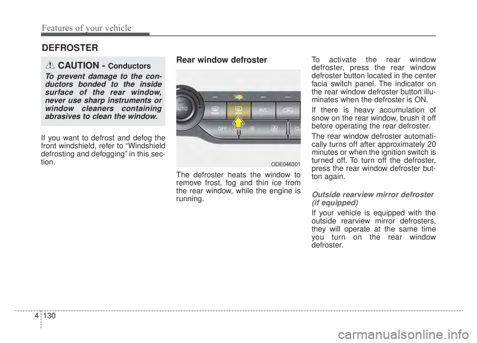
Rear window defroster
The defroster heats the window to
remove frost, fog and thin ice from
the rear window, while the engine is
running. To activate the rear window
defroster, press the rear window
defroster button located in the center
facia switch panel. The indicator on
the rear window defroster button illu-
minates when the defroster is ON.
If there is heavy accumulation of
snow on the rear window, brush it off
before operating the rear defroster.
The rear window defroster automati-
cally turns off after approximately 20
minutes or when the ignition switch is
turned off. To turn off the defroster,
press the rear window defroster but-
ton again.
Outside rearview mirror defroster
(if equipped)
If your vehicle is equipped with the
outside rearview mirror defrosters,
they will operate at the same time
you turn on the rear window
defroster.
DEFROSTER
CAUTION - Conductors
To prevent damage to the con-ductors bonded to the insidesurface of the rear window,never use sharp instruments orwindow cleaners containingabrasives to clean the window.
ODE046301
Page 270 of 687

4133
Features of your vehicle
✽ ✽NOTICE
Never place anything over the sensor
located on the instrument panel to
ensure better control of the heating
and cooling system.
ODEP049414
Page 272 of 687

4135
Features of your vehicle
Mode selection
The mode selection button controls
the direction of the air flow through
the ventilation system.
The air flow outlet port is converted
as follows:Face-Level (B, D)
Air flow is directed toward the upper
body and face. Additionally, each
outlet can be controlled to direct the
air discharged from the outlet.
Bi-Level (B, C, D, E, F)
Air flow is directed towards the face
and the floor.
Floor-Level (A, C, D, E, F)
Most of the air flow is directed to the
floor, with a small amount of the air
being directed to the windshield and
side window defrosters. Floor/Defrost-Level
(A, C, D, E, F)
Most of the air flow is directed to the
floor and the windshield with a small
amount directed to the side window
defrosters.
✽ ✽ NOTICE - 2nd row outlet
vents (E,F)
(if equipped)
• The air flow of the 2nd row outlet
vents is controlled by the front cli-
mate control system and delivered
through the inside air duct of the
floor (E, F).
• The air flow of the 2nd row outlet vents (E, F) may be weaker than
the instrument panel vents for the
long air duct.ODE046304