KIA NIRO PHEV 2022 Owners Manual
Manufacturer: KIA, Model Year: 2022, Model line: NIRO PHEV, Model: KIA NIRO PHEV 2022Pages: 710, PDF Size: 10.35 MB
Page 621 of 710

Maintenance
58
7
It is not easy to recognize the tire
damage with your own eyes. But if
there is the slightest hint of tire
damage, even though you cannot
see it, have the tire checked or
replaced because the tire damage
may cause air leakage from the tire.
If the tire is damaged by driving on a rough road, off road, pothole,
manhole, or curb stone, it will not
be covered by the warranty.
You can find out the tire information on the tire sidewall.
Page 622 of 710

759
Maintenance
FUSES
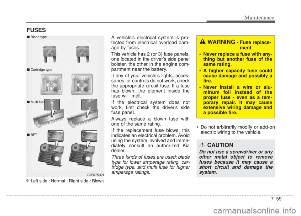
❈Left side : Normal , Right side : Blown
A vehicle’s electrical system is pro-
tected from electrical overload dam-
age by fuses.
This vehicle has 2 (or 3) fuse panels,
one located in the driver’s side panel
bolster, the other in the engine com-
partment near the battery.
If any of your vehicle’s lights, acces-
sories, or controls do not work, check
the appropriate circuit fuse. If a fuse
has blown, the element inside the
fuse will melt.
If the electrical system does not
work, first check the driver’s side
fuse panel.
Always replace a blown fuse with
one of the same rating.
If the replacement fuse blows, this
indicates an electrical problem. Avoid
using the system involved and imme-
diately consult an authorized Kia
dealer.
Three kinds of fuses are used: blade
type for lower amperage rating, car-tridge type, and multi fuse for higheramperage ratings.
Do not arbitrarily modify or add-on electric wiring to the vehicle.
WARNING- Fuse replace-
ment
Never replace a fuse with any- thing but another fuse of the
same rating.
A higher capacity fuse could cause damage and possibly a
fire.
Never install a wire or alu- minum foil instead of the
proper fuse - even as a tem-
porary repair. It may cause
extensive wiring damage and
a possible fire.
CAUTION
Do not use a screwdriver or anyother metal object to removefuses because it may cause ashort circuit and damage thesystem.
OJF075021
■
Blade type
■ Cartridge type
■ Multi fuse
■ BFT
Page 623 of 710

Maintenance
60
7
✽ ✽
NOTICE
• When replacing fuse, turn the
ignition “OFF” and turn off
switches of all electrical devices
then remove battery (-) terminal.
• The actual fuse/relay panel label may differ from equipped items.
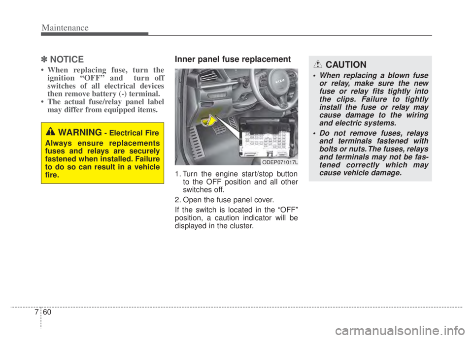
Inner panel fuse replacement
1. Turn the engine start/stop button
to the OFF position and all other
switches off.
2. Open the fuse panel cover.
If the switch is located in the “OFF”
position, a caution indicator will be
displayed in the cluster.
WARNING- Electrical Fire
Always ensure replacements
fuses and relays are securely
fastened when installed. Failure
to do so can result in a vehicle
fire.
CAUTION
When replacing a blown fuse or relay, make sure the newfuse or relay fits tightly intothe clips. Failure to tightlyinstall the fuse or relay maycause damage to the wiringand electric systems.
Do not remove fuses, relays and terminals fastened withbolts or nuts. The fuses, relaysand terminals may not be fas-tened correctly which maycause vehicle damage.
ODEP071017L
Page 624 of 710

761
Maintenance
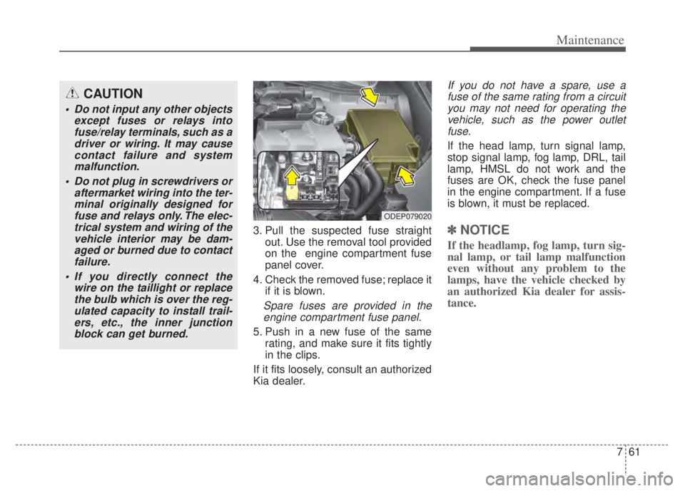
3. Pull the suspected fuse straightout. Use the removal tool provided
on the engine compartment fuse
panel cover.
4. Check the removed fuse; replace it if it is blown.
Spare fuses are provided in theengine compartment fuse panel.
5. Push in a new fuse of the same rating, and make sure it fits tightly
in the clips.
If it fits loosely, consult an authorized
Kia dealer.
If you do not have a spare, use a fuse of the same rating from a circuityou may not need for operating thevehicle, such as the power outletfuse.
If the head lamp, turn signal lamp,
stop signal lamp, fog lamp, DRL, tail
lamp, HMSL do not work and the
fuses are OK, check the fuse panel
in the engine compartment. If a fuse
is blown, it must be replaced.
✽ ✽ NOTICE
If the headlamp, fog lamp, turn sig-
nal lamp, or tail lamp malfunction
even without any problem to the
lamps, have the vehicle checked by
an authorized Kia dealer for assis-
tance.
ODEP079020
CAUTION
Do not input any other objects
except fuses or relays intofuse/relay terminals, such as adriver or wiring. It may causecontact failure and systemmalfunction.
Do not plug in screwdrivers or aftermarket wiring into the ter-minal originally designed forfuse and relays only. The elec-trical system and wiring of thevehicle interior may be dam-aged or burned due to contactfailure.
If you directly connect the wire on the taillight or replacethe bulb which is over the reg-ulated capacity to install trail-ers, etc., the inner junctionblock can get burned.
Page 625 of 710

Maintenance
62
7
Fuse switch
Always set the fuse switch to the ON
position before using the vehicle.
If you move the switch to the OFF
position, some items such as audio
and digital clock must be reset and
transmitter (or smart key) may not
work properly. When the switch is
Off, the caution indicator will be dis-
played on the instrument cluster.
Always place the fuse switch in the
ON position while driving the vehicle.
If the switch is located in the “OFF”
position, a caution indicator will be
displayed in the cluster.
Engine compartment fuse
replacement
1. Turn the engine start/stop button
to the OFF position and all other
switches off.
2. Remove the fuse panel cover by pressing the tab and pulling the
cover up. When the blade type
fuse is disconnected, remove it by
using the clip designed for chang-
ing fuses located in the engine
compartment fuse box. Upon
removal, securely insert reserve
fuse of the same rating.
ODEP071018L
ODEP079021
CAUTION - Fuse Panel
Covers
Set all switches to ON beforedriving.
If the vehicle is going to be unused for over 1 month, setall switches to OFF to preventthe batteries from draining.
The contact points of the switches may wear out withexcessive use. Please refrainfrom excessive use of theswitches (except for long-termparking for over 1 month).
Page 626 of 710

763
Maintenance
3. Check the removed fuse; replace itif it is blown. To remove or insert
the fuse, use the fuse puller in the
engine compartment fuse panel.
4. Push in a new fuse of the same rating, and make sure it fits tightly
in the clips. If it fits loosely, consult
an authorized Kia dealer.Multi fuse
If the multi fuse is blown, it must be
removed as follows:
1. Turn off the engine.
2. Disconnect the negative batterycable.
3. Remove the nuts shown in the pic- ture above.
4. Replace the fuse with a new one of the same rating.
5. Reverse these steps to reinstall the multi fuse.
✽ ✽NOTICE
Do not disassemble nor assemble the
multi fuse when it is secured with
nuts and bolts. Incorrect or partial
assembly torque may cause a fire.
Have the vehicle checked by an
authorized Kia dealer.
ODEP079022
CAUTION
After checking the fuse panel in
the engine compartment,securely install the fuse panelcover to protect against anyelectrical failure which mayoccur from water contact. Listenfor the audible clicking sound toensure the fuse panel cover issecurely fastened.
Page 627 of 710

Maintenance
64
7
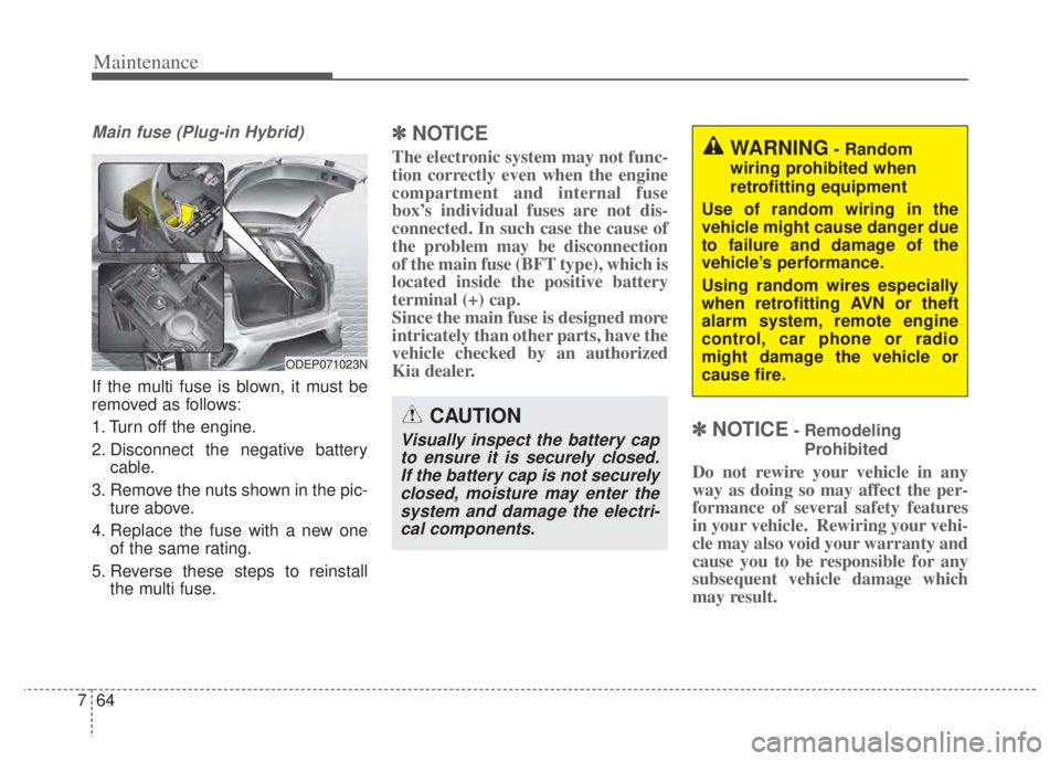
Main fuse (Plug-in Hybrid)
If the multi fuse is blown, it must be
removed as follows:
1. Turn off the engine.
2. Disconnect the negative battery
cable.
3. Remove the nuts shown in the pic- ture above.
4. Replace the fuse with a new one of the same rating.
5. Reverse these steps to reinstall the multi fuse.
✽ ✽NOTICE
The electronic system may not func-
tion correctly even when the engine
compartment and internal fuse
box’s individual fuses are not dis-
connected. In such case the cause of
the problem may be disconnection
of the main fuse (BFT type), which is
located inside the positive battery
terminal (+) cap.
Since the main fuse is designed more
intricately than other parts, have the
vehicle checked by an authorized
Kia dealer.
✽ ✽NOTICE- Remodeling
Prohibited
Do not rewire your vehicle in any
way as doing so may affect the per-
formance of several safety features
in your vehicle. Rewiring your vehi-
cle may also void your warranty and
cause you to be responsible for any
subsequent vehicle damage which
may result.
CAUTION
Visually inspect the battery capto ensure it is securely closed.If the battery cap is not securelyclosed, moisture may enter thesystem and damage the electri-cal components.
WARNING- Random
wiring prohibited when
retrofitting equipment
Use of random wiring in the
vehicle might cause danger due
to failure and damage of the
vehicle’s performance.
Using random wires especially
when retrofitting AVN or theft
alarm system, remote engine
control, car phone or radio
might damage the vehicle or
cause fire.
ODEP071023N
Page 628 of 710

765
Maintenance
Fuse/relay panel description
Driver’s side fuse panel
Inside the fuse/relay panel covers,
you can find the fuse/relay label
describing fuse/relay name and
capacity.
✽ ✽NOTICE
Not all fuse panel descriptions in
this manual may be applicable to
your vehicle. It is accurate at the
time of printing. When you inspect
the fuse panel in your vehicle, refer
to the fuse panel label.
ODEP071117N
ODEP071024L
■ Driver’s side fuse panel (Hybrid)
Page 629 of 710

Maintenance
66
7
Driver’s side fuse panel
Inside the fuse/relay panel covers,
you can find the fuse/relay label
describing fuse/relay name and
capacity.
✽ ✽
NOTICE
Not all fuse panel descriptions in
this manual may be applicable to
your vehicle. It is accurate at the
time of printing. When you inspect
the fuse panel in your vehicle, refer
to the fuse panel label.ODEP071118N
■ Driver’s side fuse panel (Plug-in Hybrid)
ODEP071024L
Page 630 of 710

767
Maintenance
Instrument panel (Driver’s side fuse panel) (Hybrid)
Fuse NameFuse ratingCircuit Protected
MODULE 510A
Electro Chromic Mirror, Audio/Video & Navigation Head Unit, Audio, Shift Lever Indicator, Air Conditioner
Control Module, Rear Seat Warmer Control Module, Front Air Ventilation Seat Control Module, Front Seat
Warmer Control Module, Head Lamp Leveling Device Actuator LH/RH, Crash Pad Switch, AMP (Amplifier),
Keyboard, OBD
MODULE 410AFront View Camera, Crash Pad Switch, Rear Corner Radar LH/RH, EPB, VESS
INTERIORLAMP10AFront Vanity Lamp LH/RH, Room Lamp, Overhead Console Lamp, Luggage Lamp, Mood Lamp, Wireless
Charger, Rain sensor, Driver warning switch
A/BAG15APassenger Occupant Detection Sensor, ACU
IG 125AEngine Room Junction Block (Fuse - DCT4, HPCU2, ACTIVE HYDRAULIC BOOSTER3, ECU3)
CLUSTER10AInstrument Cluster
MODULE 310ABCM (Body Control Module), DCT (Dual Clutch Transmission) Shift Lever, Stop Lamp Switch, Driver Door
Module, Passenger Door Module
MEMORY 27.5AActive Air Flap Unit, VESS
MODULE 810AActive Air Flap Unit, Electric Water Pump (Engine), Engine Room Junction Block (Battery C/Fan Relay),
BMS (Battery Management System) Control Module
A/BAG IND7.5AAir Conditioner Control Module, Instrument Cluster
START7.5A[With Smart Key/With Immobilizer] Inhibitor Switch