sensor KIA Optima 2010 3.G User Guide
[x] Cancel search | Manufacturer: KIA, Model Year: 2010, Model line: Optima, Model: KIA Optima 2010 3.GPages: 336, PDF Size: 6.46 MB
Page 103 of 336

437
Features of your vehicle
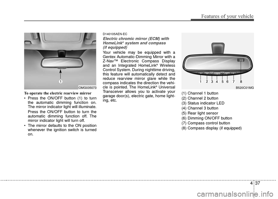
To operate the electric rearview mirror
Press the ON/OFF button (1) to turnthe automatic dimming function on.
The mirror indicator light will illuminate.
Press the ON/OFF button to turn the
automatic dimming function off. The
mirror indicator light will turn off.
The mirror defaults to the ON position whenever the ignition switch is turned
on.
D140105AEN-EC
Electric chromic mirror (ECM) withHomeLink®system and compass
(if equipped)
Your vehicle may be equipped with a
Gentex Automatic-Dimming Mirror with a
Z-Nav™ Electronic Compass Display
and an Integrated HomeLink
®Wireless
Control System. During nighttime driving,
this feature will automatically detect and
reduce rearview mirror glare while the
compass indicates the direction the vehi-
cle is pointed. The HomeLink
®Universal
Transceiver allows you to activate your
garage door(s), electric gate, home light-
ing, etc. (1) Channel 1 button
(2) Channel 2 button
(3) Status indicator LED
(4) Channel 3 button
(5) Rear light sensor
(6) Dimming ON/OFF button
(7) Compass control button
(8) Compass display (if equipped)B520C01MGOMG035073
Page 104 of 336

Features of your vehicle
38
4
Automatic-Dimming Night Vision
Safety™ (NVS®) Mirror
The NVS®Mirror in your vehicle is the
most advanced way to reduce annoying
glare in the rearview mirror during any
driving situation. For more information
regarding NVS
®mirrors and other appli-
cations, please refer to the Gentex web-
site:
www.gentex.com Automatic-dimming function
Your mirror will automatically dim upon
detecting glare from the vehicles travel-
ing behind you. The auto-dimming func-
tion can be controlled by the Dimming
ON/OFF Button:
1. Pressing the button turns the auto-
dimming function OFF which is indicat-
ed by the green Status Indicator LED
turning off.
2. Pressing the button again turns the auto-dimming function ON which is
indicated by the green Status Indicator
LED turning on.
✽ ✽NOTICE
The mirror defaults to the ON position
each time the vehicle is started.
Z-Nav™ Compass Display
The NVS™ Mirror in your vehicle is also
equipped with a Z-Nav™ Compass that
shows the vehicle Compass heading in
the Display Window using the 8 basic
cardinal headings (N, NE, E, SE, etc.).
Compass function
The Compass can be turned ON and
OFF and will remember the last state
when the ignition is cycled. To turn the
display feature ON/OFF:
1. Press and release the button to
turn the display feature OFF.
2. Press and release the button again to turn the display back ON.
Additional options can be set with press
and hold sequences of the button and
are detailed below.
There is a difference between magnetic
north and true north. The compass in the
mirror can compensate for this difference
when it knows the Magnetic Zone in
which it is operating. This is set either by
the dealer or by the user. The operating
Zone Numbers for North America are
shown in the figure on the following sec-
tion.
CAUTION
The NVS®Mirror automatically
reduces glare during driving condi- tions based upon light levels moni-tored in front of the vehicle andfrom the rear of the vehicle. Theselight sensors are visible throughopenings in the front and rear of themirror case. Any object that obstructs either light sensor willdegrade the automatic dimmingcontrol feature.
Page 129 of 336

463
Features of your vehicle
D190402ABH
Headlight position ( )
When the light switch is in the headlight
position (2nd position), the head, tail,
license and instrument panel lights are
ON.
✽ ✽NOTICE
The ignition switch must be in the ON
position to turn on the headlights.
D190403AUN
Auto light position (if equipped)
When the light switch is in the AUTO light
position, the taillights and headlights will
be turned ON or OFF automatically
depending on the amount of light outside
the vehicle.
CAUTION
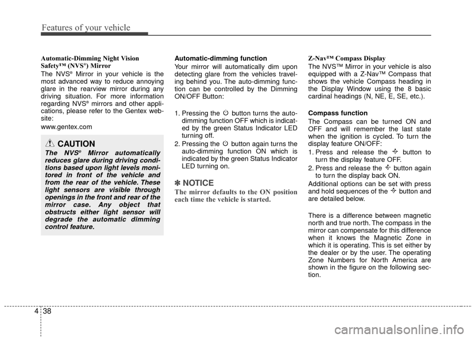
Never place anything over sensor
(1) located on the instrumentpanel. This will ensure better auto-light system control.
Don’t clean the sensor using a window cleaner. The cleaner mayleave a light film which could interfere with sensor operation.
If your vehicle has window tint or other types of coating on thefront windshield, the Auto light system may not work properly.
OUN020223OUN020222
Page 133 of 336

467
Features of your vehicle
D200101AMG
Auto control (if equipped)
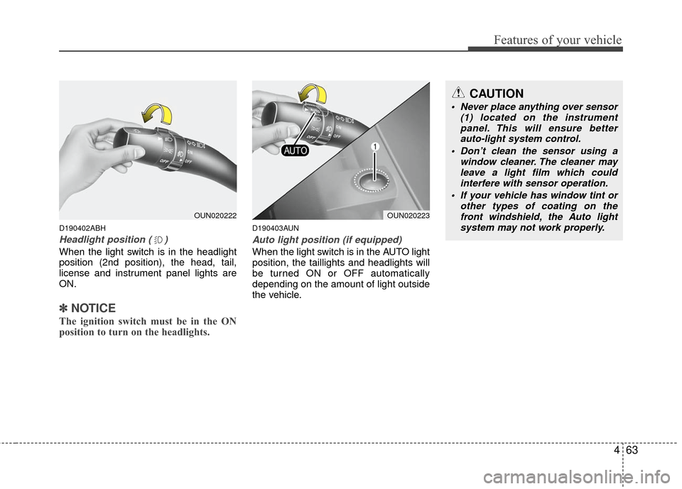
The rain sensor located on the upper end
of the windshield glass senses the
amount of rainfall and controls the wiping
cycle for the proper interval. The more it
rains, the faster the wiper operates. When
the rain stops, the wiper stops. To vary the
speed setting, turn the speed control
knob (1).If the ignition switch is turned ON when
the wiper switch is set in AUTO mode, or
the wiper switch is set in AUTO mode
when the ignition switch is ON, or the
speed control knob is turned upward
when the wiper switch is in AUTO mode,
the wiper will operate once to perform a
self-check of the system. Set the wiper to
OFF position when the wiper is not in
use.
CAUTION
When the ignition switch is ON and
the windshield wiper switch is placed in the AUTO mode, use cau-tion in the following situations toavoid any injury to the hands orother parts of the body:
Do not touch the upper end of the windshield glass facing the rainsensor.
Do not wipe the upper end of the windshield glass with a damp orwet cloth.
Do not put pressure on the wind- shield glass.
CAUTION
When washing the vehicle, set thewiper switch in the OFF position tostop the auto wiper operation.
The wiper may operate and be dam-aged if the switch is set in the AUTOmode while washing the vehicle.
Do not remove the sensor coverlocated on the upper end of the pas- senger side windshield glass.Damage to system parts couldoccur and may not be covered by your vehicle warranty.
When starting the vehicle in winter,set the wiper switch in the OFF position. Otherwise, wipers mayoperate and ice may damage the windshield wiper blades. Alwaysremove all snow and ice and defrost the windshield properly prior tooperating the windshield wipers.
ONF048067
Sensor
Page 149 of 336

483
Features of your vehicle
D240100ANF
Automatic heating and air condi-
tioning
The automatic climate control system is
controlled by simply setting the desired
temperature.
The Full Automatic Temperature Control
(FATC) system automatically controls the
heating and cooling system as follows;
1. Push the AUTO button. It is indicatedby AUTO on the display. The modes,
fan speeds, air intake and air-condi-
tioning will be controlled automatically
by temperature setting. 2. Push the temperature control button to
set the desired temperature.
If the temperature is set to the lowest
setting (Lo), the air conditioning sys-
tem will operate continuously.
3. To turn the automatic operation off, press any button except temperature
control button. If you press the mode
selection button, air-conditioning but-
ton, defrost button, air intake control
button or fan speed button, the select-
ed function will be controlled manually
while other functions operate automat-
ically.
Regardless of the temperature setting,
when using automatic operation, the air
conditioning system can automatically
turn on to decrease the humidity inside
the vehicle, even if the temperature is set
to warm.
✽ ✽ NOTICE
Never place anything over the sensor
located on the instrument panel to
ensure better control of the heating and
cooling system.
OMG045045OMG049081
Page 289 of 336

Maintenance
24
7
AIR CLEANER
G160100AUN-EC
Filter replacement
It must be replaced when necessary, and
should not be cleaned and reused. Replace the filter according to the
Maintenance Schedule.
If the vehicle is operated in extremely
dusty or sandy areas, replace the ele-ment more often than the usual recom-mended intervals.
G170100AUN-EC
Filter inspection
If the vehicle is operated in severely air-
polluted cities or on dusty rough roads for
a long period, it should be inspected
more frequently and replaced earlier.
When you replace the climate control air
filter, replace it performing the following
procedure, and be careful to avoid dam-
aging other components.
OMG075012
CAUTION
Do not drive with the air cleaner removed; this will result in exces-sive engine wear.
Use a KIA genuine part. Use of non-genuine parts could damagethe air flow sensor.
CLIMATE CONTROL AIR FILTER
Page 313 of 336

Maintenance
48
7
Driver's side fuse panel
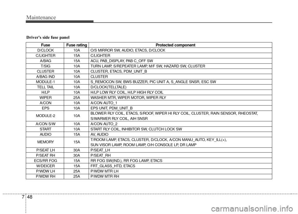
Fuse Fuse rating Protected component
D/CLOCK10A O/S MIRROR SW, AUDIO, ETACS, D/CLOCK
C/LIGHTER 15A C/LIGHTER A/BAG 15A ACU, PAB_DISPLAY, PAB C_OFF SW
T/SIG 10A TURN LAMP, S/REPEATER LAMP, M/F SW, HAZARD SW, CLUSTER
CLUSTER 10A CLUSTER, ETACS, PDM_UNIT_B
A/BAG IND 10A CLUSTER
MODULE-1 10A S_REMOCON SW, BWS BUZZER, PIC UNIT A, S_ANGLE SNSR, ESC SW TELL TAIL 10A D/CLOCK(TELLTALE)
H/LP 10A H/LP LOW RLY COIL, H/LP HIGH RLY COIL
WIPER 25A WASHER MTR, WIPER MOTOR, WIPER RLY
A/CON 10A A/CON AUTO_1
EPS 10A EPS UNIT, PDM_UNIT_B
MODULE-2 10A BLOWER RLY COIL, ETACS, S/ROOF, WIPER HI RLY COIL, CLUSTER, RAIN SENSOR, RHEOSTAT,
S/WARMER RLY COIL, AIH SNSR
A/CON S/W 10A A/CON AUTO_2 START 10A START RLY COIL, INHIBITOR SW, CLUTCH LOCK SW
AUDIO 15A AV, AUDIO
MEMORY 15AT/ROOM LAMP, ETACS, CLUSTER, D/CLOCK, A/CON MANU_AUTO, KEY_ILL(+),
SUN VISOR LAMP, ROOM LAMP, O/H CONSOLE LP, DR LAMP
P/SEAT LH 30A P/SEAT_LH
P/SEAT RH 30A P/SEAT_RH
ECS/RR FOG 15A RR FOG SW(IND.), RR FOG LAMP, ETACS W/DEICER 15A FRT_GLASS_HTD, ETACS
P/WDW LH 25A P/WDW MTR LH
P/WDW RH 25A P/WDW MTR RH
Page 315 of 336

Maintenance
50
7
Engine compartment
Description Fuse rating Protected component
ALT150A(2.7L)
FUSIBLE LINK, FUSE
125A(2.4L)
IGN1 30A
FUSE (A/BAG, TURN, CLUSTER, TELTAIL, A/BAG IND., 21, PCU, MODULE-1, SPARE)
IGN2 30A FUSE (MODULE-2, H/LP, A/CON, WIPER, SPARE, SATRT), BUTTON RELAY
TAIL 20A TAIL_LP_LH, TAIL_LP_RH
FUSIBLE RR HTD 40A MIRR HTD, RR_HTD_RELAY
LINK BLOWER 40A BLOWER MTR, FUSE (A/CON SW)
I/P B+1 30A FUSE (HAZARD, STOP LP, TPMS, T/LID, PEDAL ADJ, DR_LOCK)
I/P B+2 50AP/WINDOW RELAY, FUSE (RR FOG, P/SEAT_LH, P/SEAT_RH, W/DEICER,
POWER CONNECTOR, PDM_1, PDM_2)
ECU RLY 30A PCU, IGN COIL, INJECTOR, SENSOR
1 RAD FAN 40A(2.7L)
RAD FAN MTR
30A(2.4L)
2 ABS1 40A ABS/ESC UNIT
3 ABS2 40A ABS/ESC UNIT
4 A/CON 10A A/CON COMPRESSOR
5 S/WARMER 25A S/WARMER_LH, S/WARMER_RH
FUSE 6 P/AMP 20A P/AMP, AV-AMP
7 S/ROOF 20A S/ROOF MTR
8 P/OUTLET 25A P/OUTLET
9 FRT FOG 15A FRT FOG LAMP
10 HEAD LP HI 15A HEAD LP HI
11 HEAD LP LOW 15A HEAD LP LOW
12 HORN 15A HORN, B/ALARM HORN, HORN SW
Page 316 of 336

751
Maintenance
Description Fuse ratingProtected component
13 SNSR115A MAP, MAF, CMP, CCV, VIS, CPSV, ISCA, OCV, EGR, CAM, CKP, TDC SENSOR
14 SNSR2 15A O2 SENSOR, EGR ACTR
15 SNSR3 10A INJECTOR, PCU
16 IGN COIL 20A IGN COIL, PCU, O2 SENSOR
17 ECU-1 20A PCU
FUSE 18 F/PUMP 20A F/PUMP MTR
19 ECU 10A PCU
20 ATM 20A TCU, ATM_SOLENOID
21 BACK UP 10A BACK UP LAMP, ECM MIRROR, BWS UNIT
22 ABS 10A ABS/ESC UNIT
23 PCU 10A PCU, SPEED SENSOR
24 DRL 15A DRL CONTROL MODULE