check engine KIA Optima Hybrid 2016 4.G Workshop Manual
[x] Cancel search | Manufacturer: KIA, Model Year: 2016, Model line: Optima Hybrid, Model: KIA Optima Hybrid 2016 4.GPages: 466, PDF Size: 14.92 MB
Page 414 of 466
Maintenance
74
7
9.Install the socket in the assembly
by aligning the tabs on the socket
with the slots in the assembly.
Push the socket into assembly and
turn the socket clockwise.
10. Reinstall the headlamp assem- bly, under pad and bumper to the
body of the vehicle. Front turn signal light
1.Turn off the engine.
2.Open the hood
3.Remove the socket from the
assembly by turning the socket
counterclockwise until the tabs on
the socket align with the slots on
the assembly.
4.Remove the bulb from the socket by pressing it in and rotating it
counterclockwise until the tabs on
the bulb align with the slots in the
socket. Pull the bulb out of the
socket.
5.Insert a new bulb by inserting it into the socket and rotating it until it
locks into place.
6.Install the socket in the assembly by aligning the tabs on the socket
with the slots in the assembly.
Push the socket into assembly and
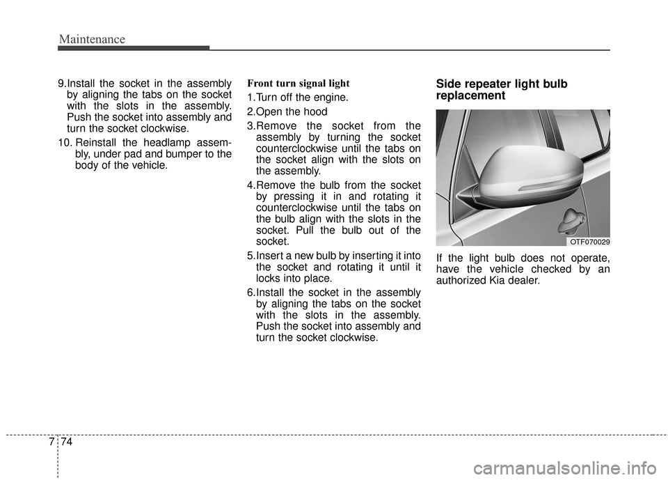
turn the socket clockwise.Side repeater light bulb
replacement
If the light bulb does not operate,
have the vehicle checked by an
authorized Kia dealer.
OTF070029
Page 416 of 466
Maintenance
76
7
If the light (LED) does not operate,
have the vehicle checked by an
authorized Kia dealer.Rear turn signal light
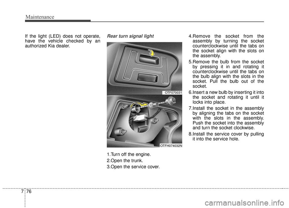
1.Turn off the engine.
2.Open the trunk.
3.Open the service cover. 4.Remove the socket from the
assembly by turning the socket
counterclockwise until the tabs on
the socket align with the slots on
the assembly.
5.Remove the bulb from the socket by pressing it in and rotating it
counterclockwise until the tabs on
the bulb align with the slots in the
socket. Pull the bulb out of the
socket.
6.Insert a new bulb by inserting it into the socket and rotating it until it
locks into place.
7.Install the socket in the assembly by aligning the tabs on the socket
with the slots in the assembly.
Push the socket into the assembly
and turn the socket clockwise.
8.Install the service cover by pulling it into the service hole.
OTF070031
OTFH074032N
Page 430 of 466
Canister
Fuel vapors generated inside the fuel
tank are absorbed and stored in the
onboard canister. When the engine is
running, the fuel vapors absorbed in
the canister are drawn into the surge
tank through the purge control sole-
noid valve.
Purge Control Solenoid Valve(PCSV)
The purge control solenoid valve is
controlled by the Engine Control
Module (ECM); when the engine
coolant temperature is low during
idling, the PCSV closes so that evap-
orated fuel is not taken into the
engine. After the engine warms up
during ordinary driving, the PCSV
opens to introduce evaporated fuel to
the engine.
3. Exhaust emission control system
The Exhaust Emission Control
System is a highly effective system
which controls exhaust emissions
while maintaining good vehicle per-
formance.
Vehicle modifications
This vehicle should not be modified.
Modification of your vehicle could
affect its performance, safety or
durability and may even violate gov-
ernmental safety and emissions reg-
ulations.
In addition, damage or performance
problems resulting from any modifi-
cation may not be covered under
warranty.
If you use unauthorized electronic
devices, it may cause the vehicle to
operate abnormally, wire damage,
battery discharge and fire. For your
safety, do not use unauthorized
electronic devices.
Engine exhaust gas precautions
(carbon monoxide)
Carbon monoxide can be present with other exhaust fumes.
Therefore, if you smell exhaust
fumes of any kind inside your vehi-
cle, have it inspected and repaired
immediately. If you ever suspect
exhaust fumes are coming into
your vehicle, drive it only with all
the windows fully open. Have your
vehicle checked and repaired
immediately.
WARNING - Exhaust
Engine exhaust gases contain
carbon monoxide (CO). Though
colorless and odorless, it is
dangerous and could be lethal if
inhaled. Follow the instructions
on this page to avoid CO poi-
soning.
790
Maintenance
Page 438 of 466
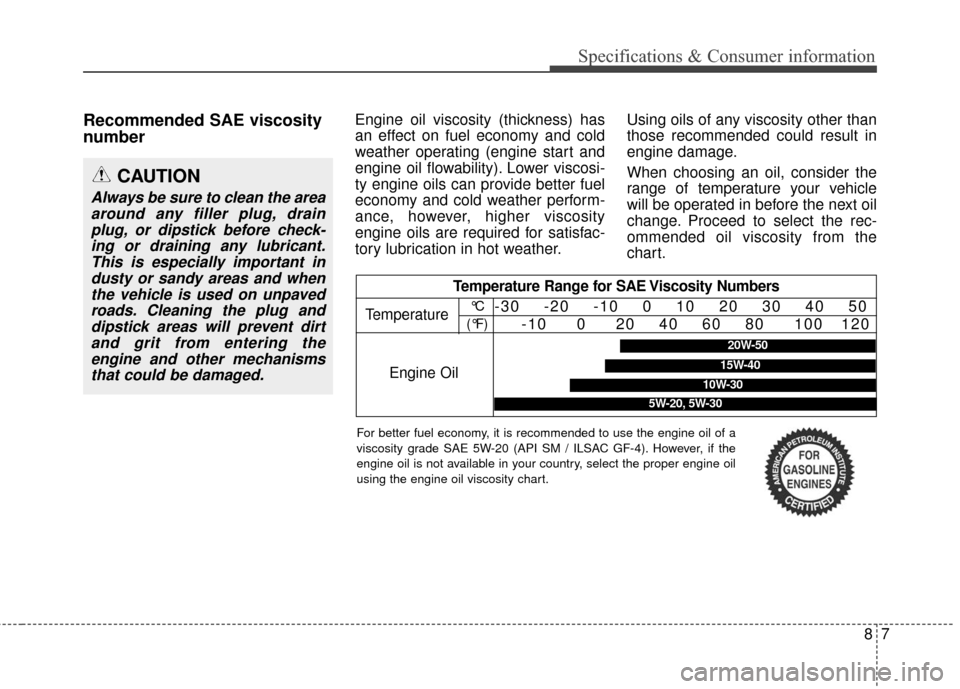
Recommended SAE viscosity
numberEngine oil viscosity (thickness) has
an effect on fuel economy and cold
weather operating (engine start and
engine oil flowability). Lower viscosi-
ty engine oils can provide better fuel
economy and cold weather perform-
ance, however, higher viscosity
engine oils are required for satisfac-
tory lubrication in hot weather.Using oils of any viscosity other than
those recommended could result in
engine damage.
When choosing an oil, consider the
range of temperature your vehicle
will be operated in before the next oil
change. Proceed to select the rec-
ommended oil viscosity from the
chart.
CAUTION
Always be sure to clean the area
around any filler plug, drainplug, or dipstick before check-ing or draining any lubricant.This is especially important industy or sandy areas and whenthe vehicle is used on unpavedroads. Cleaning the plug anddipstick areas will prevent dirtand grit from entering theengine and other mechanismsthat could be damaged.
Temperature Range for SAE Viscosity Numbers
Temperature
Engine Oil°C
(°F)-30 -20 -10 0 10 20 30 40 50 -10 0 20 40 60 80 100 120
5W-20, 5W-30
20W-50
10W-30
15W-40
87
Specifications & Consumer information
For better fuel economy, it is recommended to use the engine oil of a
viscosity grade SAE 5W-20 (API SM / ILSAC GF-4). However, if the
engine oil is not available in your country, select the proper engine oil
using the engine oil viscosity chart.
Page 443 of 466
H3
State of charge
The state of charge (SOC) gauge
indicates the hybrid battery's charge
level. If the SOC is near Low (L)
level, the vehicle automatically oper-
ates the engine to charge the battery.
The gauge will rarely approach the
High (H) level. This is normal and is
not an indication of a malfunction.
However, if the service indicator and
MIL(Malfunction indicator lamp) turn
on when the State of Charge(SOC)
is near L, have your vehicle checked
by an authorized Kia dealer immedi-
ately.
OTFH044057
CAUTION- Extendedcranking
Do not crank the engine for aprolonged period of time with-out the engine starting. Thiscould result in damage to theHEV battery and becomingtotally discharged.
Page 447 of 466
H7
Starting the Hybrid System
1.Carry the smart key into the vehi-cle.
2.Make sure the parking brake is firmly applied.
3.Place the shift lever in the P(Park) position.
In N (neutral) position, the engine
(hybrid system) will not start.
4.Depress the brake pedal.
5.Press the engine start/stop button.
6.The engine should be started with- out pressing the accelerator. In
extremely cold weather or after the
vehicle has not been operated for
several days, let the engine warm
up without depressing the acceler-
ator.
• Even if the smart key is in thevehicle, it muse be within range of
the antenna before the engine
(hybrid system) will not start.
ton is in the ACC or ON position,
if any door is open, the system
checks for the smart key. If the
smart key is not in the vehicle, the
warning, "Key is not in vehicle"
will come on, and if all doors are
closed, the chime will also sound
for about 5 seconds. The indica-
tor will turn off while the vehicle is
moving. Keep the smart key in the
vehicle when using the ACC posi-
tion or if the vehicle engine is on. If the starting procedure is fol-
lowed, the "READY" symbol on
the instrument cluster will turn on.
For more details, Please check
chapter 5.
STARTING THE HYBRID VEHICLE (SMART KEY)
Page 460 of 466
I3
Index
BSD (Blind Spot Detection) /LCA (Lane Change Assist) . . . . . . . . . . . . . . . . . . 5-37
Non-operating condition . . . . . . . . . . . . . . . . . . . . . 5-41
RCTA (Rear cross traffic alert) . . . . . . . . . . . . . . . . 5-39
Brake fluid . . . . . . . . . . . . . . . . . . . . . . . . . . . . . . . . . . 7-31\
Checking the brake fluid level . . . . . . . . . . . . . . . . . 7-31
Brake system. . . . . . . . . . . . . . . . . . . . . . . . . . . . . . . . . 5-17 Anti-lock brake system (ABS) . . . . . . . . . . . . . . . . . 5-21
Electronic stability control (ESC) . . . . . . . . . . . . . . 5-23
Good braking practices . . . . . . . . . . . . . . . . . . . . . . 5-29
Hill-start assist control (HAC) . . . . . . . . . . . . . . . . . 5-27
Parking brake . . . . . . . . . . . . . . . . . . . . . . . . . . . . . . 5-19
Power brakes . . . . . . . . . . . . . . . . . . . . . . . . . . . . . . 5-17
Vehicle stability management (VSM) . . . . . . . . . . . 5-27
Bulb wattage . . . . . . . . . . . . . . . . . . . . . . . . . . . . . . . . . . 8-4
Child restraint system . . . . . . . . . . . . . . . . . . . . . . . . . . 3-28 Lower anchor system . . . . . . . . . . . . . . . . . . . . . . . . 3-33
Tether anchorage system . . . . . . . . . . . . . . . . . . . . . 3-32
Using a child restraint system . . . . . . . . . . . . . . . . . 3-29
Climate control air filter . . . . . . . . . . . . . . . . . . . . . . . . 7-36 Filter inspection . . . . . . . . . . . . . . . . . . . . . . . . . . . . 7-36
Filter replacement. . . . . . . . . . . . . . . . . . . . . . . . . . . 7-36
Coolant . . . . . . . . . . . . . . . . . . . . . . . . . . . . . . . . . . . . \
. 7-27 Changing the coolant . . . . . . . . . . . . . . . . . . . . . . . . 7-30
Engine coolant . . . . . . . . . . . . . . . . . . . . . . . . . . . . . 7-27 Inverter coolant. . . . . . . . . . . . . . . . . . . . . . . . . . . . . 7-27
Cruise Control system . . . . . . . . . . . . . . . . . . . . . . . . . 5-31 To cancel cruise control . . . . . . . . . . . . . . . . . . . . . . 5-33
To decrease the cruising speed . . . . . . . . . . . . . . . . . 5-32
To increase cruise control set speed . . . . . . . . . . . . . 5-32
To resume cruising speed at more than approximately25 mph (40 km/h) . . . . . . . . . . . . . . . . . . . . . . . . . 5-34
To set cruise control speed . . . . . . . . . . . . . . . . . . . . 5-31
To temporarily accelerate with the cruise control on . . 5-33
To turn cruise control off . . . . . . . . . . . . . . . . . . . . . 5-34
Defroster . . . . . . . . . . . . . . . . . . . . . . . . . . . . . . . . . . . . \
4-99 Rear window defroster . . . . . . . . . . . . . . . . . . . . . . . 4-99
Dimensions . . . . . . . . . . . . . . . . . . . . . . . . . . . . . . . . . . . 8-\
2
Door locks. . . . . . . . . . . . . . . . . . . . . . . . . . . . . . . . . . . 4-\
14 Auto door lock/unlock feature . . . . . . . . . . . . . . . . . 4-16
Child-protector rear door lock . . . . . . . . . . . . . . . . . 4-16
Impact sensing door unlock system . . . . . . . . . . . . . 4-16
Operating door locks from inside the vehicle . . . . . 4-14
Operating door locks from outside the vehicle . . . . 4-14
Driver position memory system . . . . . . . . . . . . . . . . . . 4-35 Easy access function . . . . . . . . . . . . . . . . . . . . . . . . 4-36
Storing positions into memory . . . . . . . . . . . . . . . . . 4-35
C
D
Page 461 of 466
Index
4I
Economical operation . . . . . . . . . . . . . . . . . . . . . . . . . . 5-43
Emergency starting . . . . . . . . . . . . . . . . . . . . . . . . . . . . . 6-5Jump starting . . . . . . . . . . . . . . . . . . . . . . . . . . . . . . . 6-5
Push-starting . . . . . . . . . . . . . . . . . . . . . . . . . . . . . . . . 6-6
Emission control system . . . . . . . . . . . . . . . . . . . . . . . . 7-89
Engine . . . . . . . . . . . . . . . . . . . . . . . . . . . . . . . . . . . . \
. . . 8-2
Engine compartment. . . . . . . . . . . . . . . . . . . . . . . . . 2-6,7-3
Engine number . . . . . . . . . . . . . . . . . . . . . . . . . . . . . . . . 8-9
Engine oil . . . . . . . . . . . . . . . . . . . . . . . . . . . . . . . . . . . 7-\
25 Changing the engine oil and filter . . . . . . . . . . . . . . 7-26
Checking the engine oil level . . . . . . . . . . . . . . . . . . 7-25
Engine start/stop button . . . . . . . . . . . . . . . . . . . . . . . . . 5-6 ENGINE START/STOP button position . . . . . . . . . . 5-6
Illuminated ENGINE START/STOP button . . . . . . . 5-6
Explanation of scheduled maintenance items . . . . . . . 7-21
Exterior overview . . . . . . . . . . . . . . . . . . . . . . . . . . . . . . 2-2
Fuel filler lid . . . . . . . . . . . . . . . . . . . . . . . . . . . . . . . . . 4-28 Closing the fuel filler lid . . . . . . . . . . . . . . . . . . . . . 4-28
Emergency fuel filler lid release . . . . . . . . . . . . . . . 4-30
Opening the fuel filler lid. . . . . . . . . . . . . . . . . . . . . 4-28
Fuel requirements . . . . . . . . . . . . . . . . . . . . . . . . . . . . . . 1-2 Do not use methanol . . . . . . . . . . . . . . . . . . . . . . . . . 1-3
Fuel Additives . . . . . . . . . . . . . . . . . . . . . . . . . . . . . . 1-4 Gasoline containing alcohol and methanol . . . . . . . . 1-2
Gasoline containing MMT . . . . . . . . . . . . . . . . . . . . . 1-3
Operation in foreign countries . . . . . . . . . . . . . . . . . . 1-4
Fuses . . . . . . . . . . . . . . . . . . . . . . . . . . . . . . . . . . . . \
. . . 7-57 Fuse/relay panel description. . . . . . . . . . . . . . . . . . . 7-62
Gross vehicle weight. . . . . . . . . . . . . . . . . . . . . . . . . . . . 8-2
HEV powertrain . . . . . . . . . . . . . . . . . . . . . . . . . . . . . . . 1-5
Hood . . . . . . . . . . . . . . . . . . . . . . . . . . . . . . . . . . . . \
. . . 4-26 Closing the hood . . . . . . . . . . . . . . . . . . . . . . . . . . . 4-26
Opening the hood . . . . . . . . . . . . . . . . . . . . . . . . . . 4-26
Hybrid Kia Hybrid system . . . . . . . . . . . . . . . . . . . . . . . . . . . H2
State of charge (SOC) . . . . . . . . . . . . . . . . . . . . . . . . H3
Optima HEV energy flow . . . . . . . . . . . . . . . . . . . . . . H4
The componets of hybrid vehicle . . . . . . . . . . . . . . . . H9
The air intake of hybrid battery . . . . . . . . . . . . . . . . H15
The ECO level display mode . . . . . . . . . . . . . . . . . . . H2
The EV MODE . . . . . . . . . . . . . . . . . . . . . . . . . . . . 4-77
The ECO GUIDE . . . . . . . . . . . . . . . . . . . . . . . . . . . 4-49
E
F
G
H
Page 462 of 466
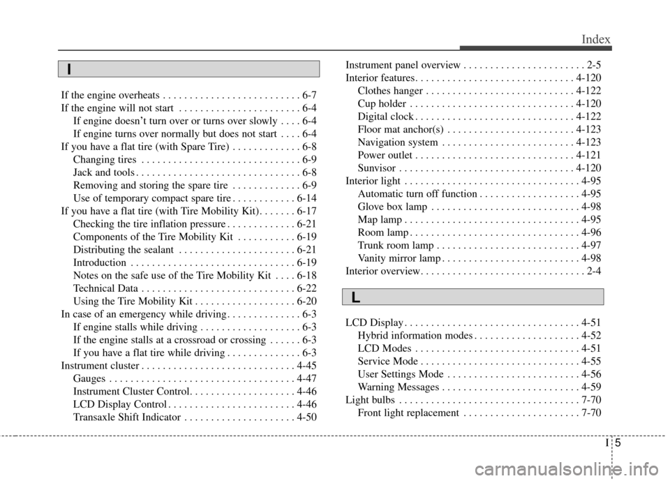
I5
Index
If the engine overheats . . . . . . . . . . . . . . . . . . . . . . . . . . 6-7
If the engine will not start . . . . . . . . . . . . . . . . . . . . . . . 6-4If engine doesn’t turn over or turns over slowly . . . . 6-4
If engine turns over normally but does not start . . . . 6-4
If you have a flat tire (with Spare Tire) . . . . . . . . . . . . . 6-8 Changing tires . . . . . . . . . . . . . . . . . . . . . . . . . . . . . . 6-9
Jack and tools . . . . . . . . . . . . . . . . . . . . . . . . . . . . . . . 6-8
Removing and storing the spare tire . . . . . . . . . . . . . 6-9
Use of temporary compact spare tire . . . . . . . . . . . . 6-14
If you have a flat tire (with Tire Mobility Kit). . . . . . . 6-17 Checking the tire inflation pressure . . . . . . . . . . . . . 6-21
Components of the Tire Mobility Kit . . . . . . . . . . . 6-19
Distributing the sealant . . . . . . . . . . . . . . . . . . . . . . 6-21
Introduction . . . . . . . . . . . . . . . . . . . . . . . . . . . . . . . 6-19
Notes on the safe use of the Tire Mobility Kit . . . . 6-18
Technical Data . . . . . . . . . . . . . . . . . . . . . . . . . . . . . 6-22
Using the Tire Mobility Kit . . . . . . . . . . . . . . . . . . . 6-20
In case of an emergency while driving . . . . . . . . . . . . . . 6-3 If engine stalls while driving . . . . . . . . . . . . . . . . . . . 6-3
If the engine stalls at a crossroad or crossing . . . . . . 6-3
If you have a flat tire while driving . . . . . . . . . . . . . . 6-3
Instrument cluster . . . . . . . . . . . . . . . . . . . . . . . . . . . . . 4-45 Gauges . . . . . . . . . . . . . . . . . . . . . . . . . . . . . . . . . . . 4-\
47
Instrument Cluster Control. . . . . . . . . . . . . . . . . . . . 4-46
LCD Display Control . . . . . . . . . . . . . . . . . . . . . . . . 4-46
Transaxle Shift Indicator . . . . . . . . . . . . . . . . . . . . . 4-50 Instrument panel overview . . . . . . . . . . . . . . . . . . . . . . . 2-5
Interior features. . . . . . . . . . . . . . . . . . . . . . . . . . . . . . 4-120
Clothes hanger . . . . . . . . . . . . . . . . . . . . . . . . . . . . 4-122
Cup holder . . . . . . . . . . . . . . . . . . . . . . . . . . . . . . . 4-120
Digital clock . . . . . . . . . . . . . . . . . . . . . . . . . . . . . . 4-122
Floor mat anchor(s) . . . . . . . . . . . . . . . . . . . . . . . . 4-123
Navigation system . . . . . . . . . . . . . . . . . . . . . . . . . 4-123
Power outlet . . . . . . . . . . . . . . . . . . . . . . . . . . . . . . 4-121
Sunvisor . . . . . . . . . . . . . . . . . . . . . . . . . . . . . . . . . 4-120
Interior light . . . . . . . . . . . . . . . . . . . . . . . . . . . . . . . . . 4-95 Automatic turn off function . . . . . . . . . . . . . . . . . . . 4-95
Glove box lamp . . . . . . . . . . . . . . . . . . . . . . . . . . . . 4-98
Map lamp . . . . . . . . . . . . . . . . . . . . . . . . . . . . . . . . . 4-95
Room lamp . . . . . . . . . . . . . . . . . . . . . . . . . . . . . . . . 4-96
Trunk room lamp . . . . . . . . . . . . . . . . . . . . . . . . . . . 4-97
Vanity mirror lamp . . . . . . . . . . . . . . . . . . . . . . . . . . 4-98
Interior overview. . . . . . . . . . . . . . . . . . . . . . . . . . . . . . . 2-4
LCD Display . . . . . . . . . . . . . . . . . . . . . . . . . . . . . . . . . 4-51 Hybrid information modes . . . . . . . . . . . . . . . . . . . . 4-52
LCD Modes . . . . . . . . . . . . . . . . . . . . . . . . . . . . . . . 4-51
Service Mode . . . . . . . . . . . . . . . . . . . . . . . . . . . . . . 4-55
User Settings Mode . . . . . . . . . . . . . . . . . . . . . . . . . 4-56
Warning Messages . . . . . . . . . . . . . . . . . . . . . . . . . . 4-59
Light bulbs . . . . . . . . . . . . . . . . . . . . . . . . . . . . . . . . . . 7-70\
Front light replacement . . . . . . . . . . . . . . . . . . . . . . 7-70
I
L