fog light KIA PICANTO 2016 Owners Manual
[x] Cancel search | Manufacturer: KIA, Model Year: 2016, Model line: PICANTO, Model: KIA PICANTO 2016Pages: 488, PDF Size: 31.22 MB
Page 76 of 488
4
Keys / 4-3
Remote keyless entry / 4-6
Smart key / 4-9
Theft-alarm system / 4-12
Door locks / 4-15
Tailgate / 4-19
Windows / 4-21
Hood / 4-26
Fuel filler lid / 4-28
Sunroof / 4-31
Steering wheel / 4-35
Mirrors / 4-38
Instrument cluster / 4-42
Rear parking assist system / 4-71
Hazard warning flasher / 4-74
Lighting / 4-75
Wipers and washers / 4-83
Interior light / 4-87
Defroster / 4-90
Manual climate control system / 4-91
Automatic climate control system / 4-100
Windshield defrosting and defogging / 4-107
Features of your vehicle
Page 138 of 488
463
Features of your vehicle
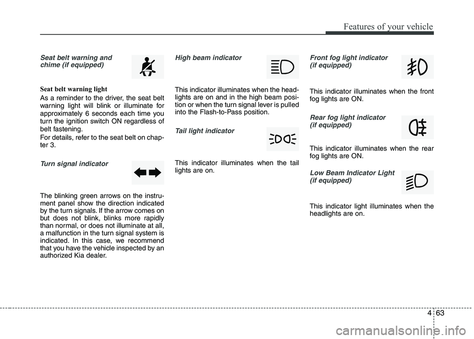
Seat belt warning andchime (if equipped)
Seat belt warning light
As a reminder to the driver, the seat belt
warning light will blink or illuminate for
approximately 6 seconds each time you
turn the ignition switch ON regardless of
belt fastening.
For details, refer to the seat belt on chap- ter 3.
Turn signal indicator
The blinking green arrows on the instru-
ment panel show the direction indicated
by the turn signals. If the arrow comes on
but does not blink, blinks more rapidly
than normal, or does not illuminate at all,
a malfunction in the turn signal system is
indicated. In this case, we recommend
that you have the vehicle inspected by an
authorized Kia dealer.
High beam indicator
This indicator illuminates when the head- lights are on and in the high beam posi-
tion or when the turn signal lever is pulled
into the Flash-to-Pass position.
Tail light indicator
This indicator illuminates when the tail lights are on.
Front fog light indicator
(if equipped)
This indicator illuminates when the front
fog lights are ON.
Rear fog light indicator (if equipped)
This indicator illuminates when the rear
fog lights are ON.
Low Beam Indicator Light
(if equipped)
This indicator light illuminates when the headlights are on.
Page 155 of 488
Features of your vehicle
80
4
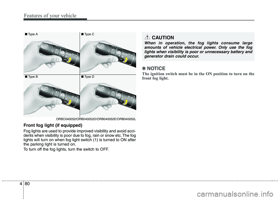
Front fog light (if equipped)
Fog lights are used to provide improved visibility and avoid acci-
dents when visibility is poor due to fog, rain or snow etc. The fog
lights will turn on when fog light switch (1) is turned to ON after
the parking light is turned on.
To turn off the fog lights, turn the switch to OFF.
✽✽
NOTICE
The ignition switch must be in the ON position to turn on the
front fog light.
CAUTION
When in operation, the fog lights consume large amounts of vehicle electrical power. Only use the fog
lights when visibility is poor or unnecessary battery andgenerator drain could occur.
■ Type A
■ Type B
ORBC040052/ORB040052D/ORB040052E/ORB040052L ■
Type C
■ Type D
Page 156 of 488
481
Features of your vehicle
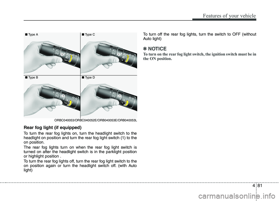
Rear fog light (if equipped)
To turn the rear fog lights on, turn the headlight switch to the
headlight on position and turn the rear fog light switch (1) to theon position.
The rear fog lights turn on when the rear fog light switch is
turned on after the headlight switch is in the parklight positionor highlight position .
To turn the rear fog lights off, turn the rear fog light switch to the
on position again or turn the headlight switch off. (with Autolight)To turn off the rear fog lights, turn the switch to OFF (without
Auto light)
✽✽
NOTICE
To turn on the rear fog light switch, the ignition switch must be in
the ON position.
■ Type A
■ Type B
ORBC040053/ORBC040052E/ORB040053E/ORB040053L ■
Type C
■ Type D
Page 171 of 488
Features of your vehicle
96
4
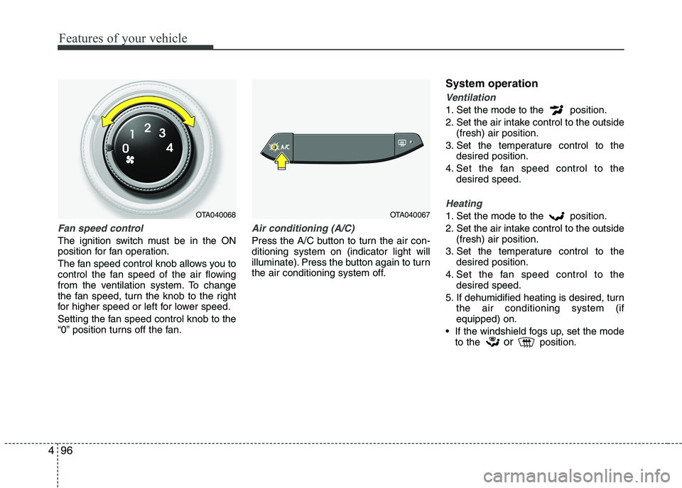
Fan speed control
The ignition switch must be in the ON
position for fan operation.
The fan speed control knob allows you to
control the fan speed of the air flowing
from the ventilation system. To change
the fan speed, turn the knob to the right
for higher speed or left for lower speed.
Setting the fan speed control knob to the
“0” position turns off the fan.
Air conditioning (A/C)
Press the A/C button to turn the air con- ditioning system on (indicator light will
illuminate). Press the button again to turn
the air conditioning system off. System operation
Ventilation
1. Set the mode to the position.
2. Set the air intake control to the outside
(fresh) air position.
3. Set the temperature control to the desired position.
4. Set the fan speed control to the desired speed.
Heating
1. Set the mode to the position.
2. Set the air intake control to the outside(fresh) air position.
3. Set the temperature control to the desired position.
4. Set the fan speed control to the desired speed.
5. If dehumidified heating is desired, turn the air conditioning system (if equipped) on.
If the windshield fogs up, set the mode to the or
position.OTA040068OTA040067
Page 173 of 488
Features of your vehicle
98
4
Air conditioning system operation tips
If the vehicle has been parked in direct
sunlight during hot weather, open the
windows for a short time to let the hot
air inside the vehicle escape.
To help reduce moisture inside of the windows on rainy or humid days,
decrease the humidity inside the vehi-
cle by operating the air conditioningsystem.
During air conditioning system opera- tion, you may occasionally notice aslight change in engine speed as the
air conditioning compressor cycles.
This is a normal system operation
characteristic.
Use the air conditioning system every month only for a few minutes to ensure
maximum system performance. When using the air conditioning sys-
tem, you may notice clear water drip-
ping (or even puddling) on the ground
under the passenger side of the vehi-
cle. This is a normal system operation
characteristic.
Operating the air conditioning system in the recirculated air position provides
maximum cooling, however, continual
operation in this mode may cause the
air inside the vehicle to become stale.
During cooling operation, you may occasionally notice a misty air flow
because of rapid cooling and humid air
intake. This is a normal system opera-
tion characteristic.
If you operate air conditioner exces- sively, the difference between the tem-
perature of the outside air and that ofthe windshield could cause the outer
surface of the windshield to fog up,
causing loss of visibility. In this case,
set the mode selection knob or button
to the position and fan speed con-
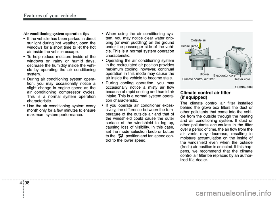
trol to the lower speed. Climate control air filter (if equipped) The climate control air filter installed
behind the glove box filters the dust or
other pollutants that come into the vehi-cle from the outside through the heating
and air conditioning system. If dust or
other pollutants accumulate in the filter
over a period of time, the air flow from the
air vents may decrease, resulting in
moisture accumulation on the inside of
the windshield even when the outside
(fresh) air position is selected. If this hap-
pens, we recommend that the climate
control air filter be replaced by an author-
ized Kia dealer.
OHM048209
Outside air
Recirculated air
Climate control air filter Blower
Evaporator core
Heater core
Page 443 of 488
765
Maintenance
SymbolFuse ratingProtected Component
MULTI FUSE80AEPS Control Module
125AAlternator, PCB Fuse & Relay Box
FUSE
50AI/P Junction Box (Power Connector Fuse : F1 10A / F2 20A,
Fuse : F24 10A / F25 10A / F26 10A / F27 15A, Tail Lamp Relay)
40AProjection Type : E/R Sub Fuse Box (Fuse : F1 10A / F2 20A / F4 15A / F5 10A / F7 10A )
50AI/P Junction Box (Fuse : F8 20A / F9 25A / F10 15A / F16 15A / F17 25A / F18 15A / F19 10A
/ F35 10A, Power Window Relay)
40AE/R Junction Box (Fuse : F11 15A), Ignition Switch, PDM Relay Box (ESCL Relay)
40AABS Control Relay, ESC Control Relay
30AABS Control Relay, ESC Control Relay
40ARear Defogger Relay
40APCB Fuse & Relay Box (Start Relay), Ignition Switch, PDM Relay Box (ESCL Relay)
30APCB Fuse & Relay Box (Engine Control Relay, Fuse : F23 10A)
40APCB Fuse & Relay Box (Blower Relay)
40APCB Fuse & Relay Box (Cooling Fan Relay)
FUSE
(General head light type)10AInstrument Cluster, Head Lamp RH, PCB Fuse & Relay Box (Head Lamp (HI) Relay)
2FUEL PUMP
(FFV)
VACCUM PUMP (EU K3 AT)
15APCB Fuse & Relay Box (Fuel Pump #2 Relay)
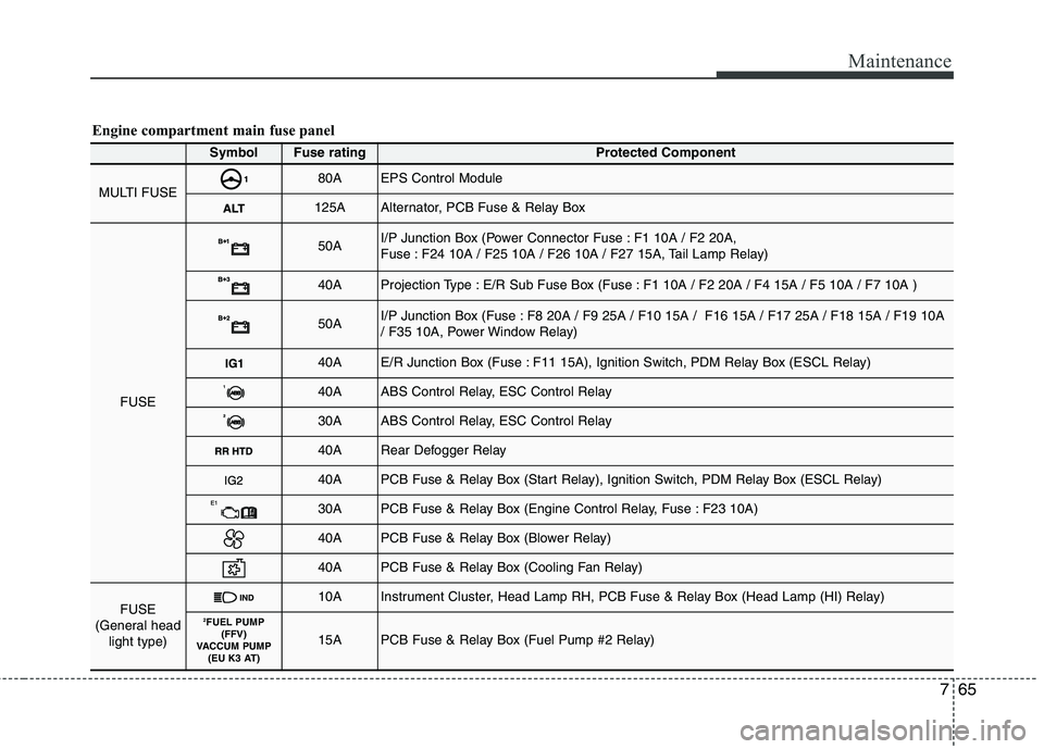
Engine compartment main fuse panel
Page 447 of 488
769
Maintenance
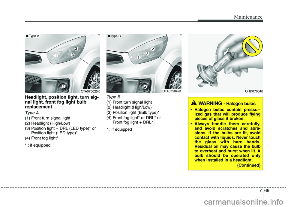
Headlight, position light, turn sig-
nal light, front fog light bulbreplacement
Type A
(1) Front turn signal light
(2) Headlight (High/Low)
(3) Position light + DRL (LED type)* orPosition light (LED type)*
(4) Front fog light*
* : if equipped
Type B
(1) Front turn signal light
(2) Headlight (High/Low)
(3) Position light (Bulb type)*
(4) Front fog light* or DRL* or Front fog light + DRL*
* : if equipped
OHD076046
WARNING - Halogen bulbs
Halogen bulbs contain pressur-
ized gas that will produce flying
pieces of glass if broken.
Always handle them carefully, and avoid scratches and abra-
sions. If the bulbs are lit, avoid
contact with liquids. Never touchthe glass with bare hands.
Residual oil may cause the bulb
to overheat and burst when lit. A
bulb should be operated onlywhen installed in a headlight.
(Continued)
OTA075042K
■
Type BOTA075025K
■Type A
Page 449 of 488
771
Maintenance
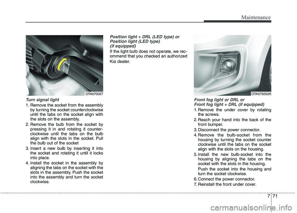
Turn signal light
1. Remove the socket from the assemblyby turning the socket counterclockwise
until the tabs on the socket align with
the slots on the assembly.
2. Remove the bulb from the socket by pressing it in and rotating it counter-
clockwise until the tabs on the bulb
align with the slots in the socket. Pull
the bulb out of the socket
3. Insert a new bulb by inserting it into the socket and rotating it until it locks
into place.
4. Install the socket in the assembly by aligning the tabs on the socket with the
slots in the assembly. Push the socket
into the assembly and turn the socket
clockwise.
Position light + DRL (LED type) or
Position light (LED type)(if equipped)
If the light bulb does not operate, we rec-
ommend that you checked an authorized
Kia dealer.
Front fog light or DRL or Front fog light + DRL (if equipped)
1. Remove the under cover by rotating the screws.
2. Reach your hand into the back of the front bumper.
3. Disconnect the power connector.
4. Remove the bulb-socket from the housing by turning the socket counter
clockwise until the tabs on the socketalign with the slots on the housing.
5. Install the new bulb-socket into the housing by aligning the tabs on the
socket with the slots in the housing.
Push the socket into the housing and
turn the socket clockwise.
6. Connect the power connector.
7. Reinstall the front under cover.
OTA075052KOTA070027
Page 450 of 488
Maintenance
72
7
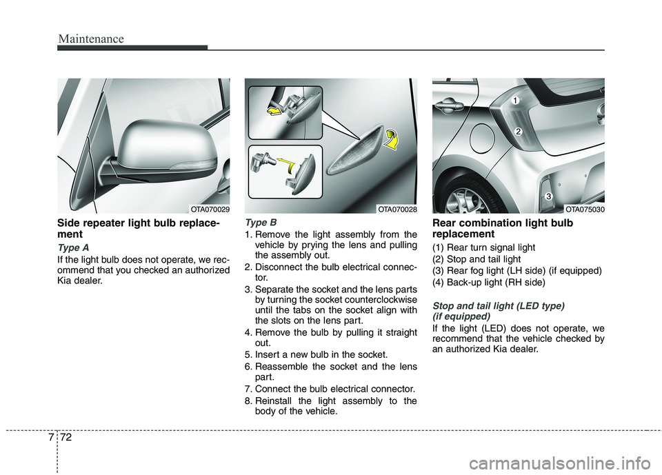
Side repeater light bulb replace- ment
Type A
If the light bulb does not operate, we rec-
ommend that you checked an authorized
Kia dealer.
Type B
1. Remove the light assembly from the
vehicle by prying the lens and pulling
the assembly out.
2. Disconnect the bulb electrical connec- tor.
3. Separate the socket and the lens parts by turning the socket counterclockwise
until the tabs on the socket align with
the slots on the lens part.
4. Remove the bulb by pulling it straight out.
5. Insert a new bulb in the socket.
6. Reassemble the socket and the lens part.
7. Connect the bulb electrical connector.
8. Reinstall the light assembly to the body of the vehicle. Rear combination light bulb replacement
(1) Rear turn signal light (2) Stop and tail light
(3) Rear fog light (LH side) (if equipped)
(4) Back-up light (RH side)
Stop and tail light (LED type)
(if equipped)
If the light (LED) does not operate, we
recommend that the vehicle checked by
an authorized Kia dealer.
OTA070028OTA075030OTA070029