fuse KIA RIO 2021 Owners Manual
[x] Cancel search | Manufacturer: KIA, Model Year: 2021, Model line: RIO, Model: KIA RIO 2021Pages: 534, PDF Size: 13.49 MB
Page 17 of 534
25
Your vehicle at a glance
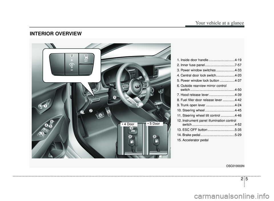
INTERIOR OVERVIEW
1. Inside door handle ............................4-19
2. Inner fuse panel ................................7-57
3. Power window switches ....................4-33
4. Central door lock switch....................4-20
5. Power window lock button ................4-37
6. Outside rearview mirror controlswitch ................................................4-50
7. Hood release lever ............................4-39
8. Fuel filler door release lever .............4-42
9. Trunk open lever ...............................4-24
10. Steering wheel ................................4-45
11. Steering wheel tilt control ...............4-46
12. Instrument panel illumination control switch ..............................................4-52
13. ESC OFF button .............................5-35
14. Brake pedal .....................................5-29
15. Accelerator pedal
OSC010003N
• 4 Door
SC PE USA 2.qxp 10/23/2020 5:32 PM Page 5
Page 19 of 534
27
Your vehicle at a glance
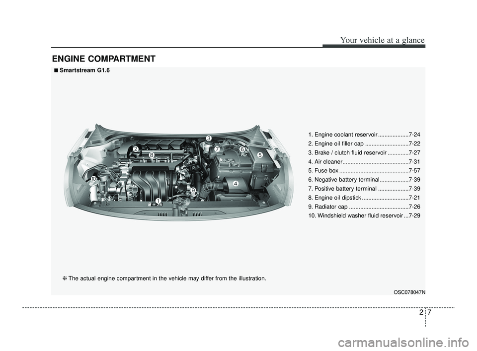
ENGINE COMPARTMENT
OSC078047N
■ ■Smartstream G1.6❈ The actual engine compartment in the vehicle may differ from the illustration. 1. Engine coolant reservoir ...................7-24
2. Engine oil filler cap ...........................7-22
3. Brake / clutch fluid reservoir .............7-27
4. Air cleaner.........................................7-31
5. Fuse box ...........................................7-57
6. Negative battery terminal..................7-39
7. Positive battery terminal ...................7-39
8. Engine oil dipstick .............................7-21
9. Radiator cap .....................................7-26
10. Windshield washer fluid reservoir ...7-29
SC PE USA 2.qxp 10/23/2020 5:32 PM Page 7
Page 60 of 534
341
Safety features of your vehicle
If an air bag deploys, there may bea loud noise followed by a fine dust
released in the vehicle. These con-
ditions are normal and are not haz-
ardous - the air bags are packed in
this fine powder. The dust generat-
ed during air bag deployment may
cause skin or eye irritation as well
as aggravate asthma for some per-
sons. Always wash all exposed
skin areas thoroughly with cold
water and a mild soap after an
accident in which the air bags were
deployed. The SRS can function only when
the ignition switch is in the ON
position. If the SRS air bag warning
light does not illuminate, or contin-
uously remains on after illuminat-
ing for about 6 seconds when the
ignition switch is turned to the ON
position, or after the engine is
started, comes on while driving,
the SRS is not working properly. If
this occurs, have your vehicle
immediately inspected by an
authorized Kia dealer.
✽ ✽ NOTICE
Before you replace a fuse or discon-
nect a battery terminal, turn the igni-
tion switch to the LOCK position
and remove the ignition key. Never
remove or replace the air bag related
fuse(s) when the ignition switch is in
the ON position. Failure to heed this
warning will cause the SRS air bag
warning light to illuminate.
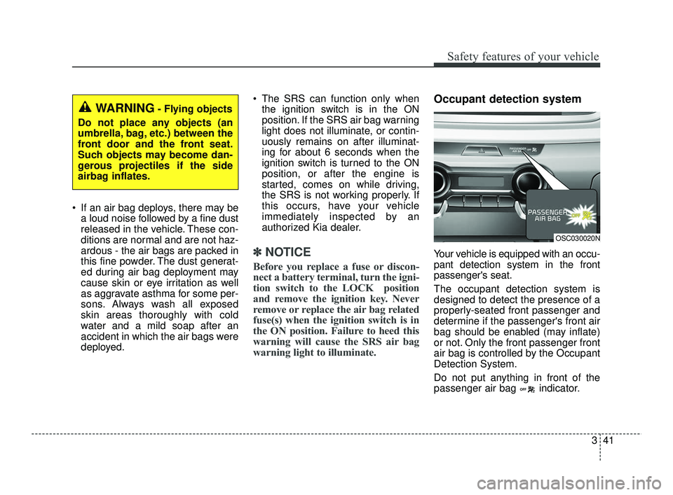
Occupant detection system
Your vehicle is equipped with an occu-
pant detection system in the front
passenger's seat.
The occupant detection system is
designed to detect the presence of a
properly-seated front passenger and
determine if the passenger's front air
bag should be enabled (may inflate)
or not. Only the front passenger front
air bag is controlled by the Occupant
Detection System.
Do not put anything in front of the
passenger air bag indicator.
WARNING- Flying objects
Do not place any objects (an
umbrella, bag, etc.) between the
front door and the front seat.
Such objects may become dan-
gerous projectiles if the side
airbag inflates.
OSC030020N
SC PE USA 3.QXP 10/23/2020 5:35 PM Page 41
Page 118 of 534
437
Features of your vehicle
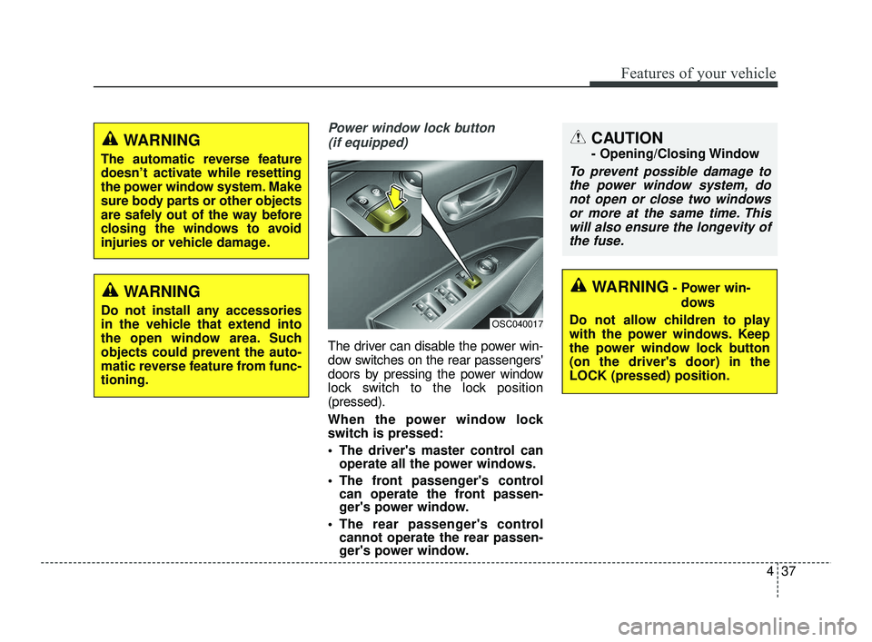
Power window lock button (if equipped)
The driver can disable the power win-
dow switches on the rear passengers'
doors by pressing the power window
lock switch to the lock position
(pressed).
When the power window lock
switch is pressed:
The driver's master control can operate all the power windows.
The front passenger's control can operate the front passen-
ger's power window.
The rear passenger's control cannot operate the rear passen-
ger's power window.
CAUTION
- Opening/Closing Window
To prevent possible damage to
the power window system, donot open or close two windowsor more at the same time. Thiswill also ensure the longevity ofthe fuse.
OSC040017
WARNING- Power win-
dows
Do not allow children to play
with the power windows. Keep
the power window lock button
(on the driver's door) in the
LOCK (pressed) position.
WARNING
The automatic reverse feature
doesn’t activate while resetting
the power window system. Make
sure body parts or other objects
are safely out of the way before
closing the windows to avoid
injuries or vehicle damage.
WARNING
Do not install any accessories
in the vehicle that extend into
the open window area. Such
objects could prevent the auto-
matic reverse feature from func-
tioning.
SC PE USA 4.QXP 10/23/2020 5:41 PM Page 37
Page 158 of 534

477
Features of your vehicle
Press clutch pedal to start engine(for smart key system and ManualTransmission)
This warning message illuminates if the ENGINE START/STOP but-
ton changes to the ACC position
twice by pressing the button
repeatedly without depressing the
clutch pedal.
It means that you should depress the clutch pedal to start the engine.
Key not in vehicle (for smart key
system)
This warning message illuminates if the smart key is not in the vehicle
when you press the ENGINE
START/STOP button.
It means that you should always have the smart key with you.
Key not detected (for smart key
system)
This warning message illuminates if the smart key is not detected
when you press the ENGINE
START/STOP button.
Press START button again (for
smart key system)
This warning message illuminates if you can not operate the ENGINE
START/STOP button when there is
a problem with the ENGINE
START/STOP button system.
It means that you could start the engine by pressing the ENGINE
START/STOP button once more.
If the warning illuminates each time you press the ENGINE
START/STOP button, have your
vehicle inspected by an authorized
Kia dealer.
Press START button with key (for
smart key system)
This warning message illuminates if you press the ENGINE
START/STOP button while the
warning message “Key not detect-
ed” is illuminating.
At this time, the immobilizer indica- tor light blinks.
Check BRAKE SWITH fuse (for
smart key system and IntelligentVariable Transmission)
This warning message illuminates if the brake switch fuse is discon-
nected.
It means that you should replace the fuse with a new one. If that is
not possible, you can start the
engine by pressing the ENGINE
START/STOP button for 10 sec-
onds in the ACC position.
SC PE USA 4.QXP 10/23/2020 5:43 PM Page 77
Page 253 of 534
Driving your vehicle
16
5
(Continued)
• When the stop lamp fuse is blown,
you cannot start the engine nor-
mally.
Replace the fuse with a new one. If
it is not possible, you can start the
engine by pressing the ENGINE
START/STOP button for 10 sec-
onds while it is in the ACC posi-
tion. The engine can start without
depressing the brake pedal. But
for your safety, always depress the
brake pedal and clutch pedal
before starting the engine.Stopping the engine
(Manual Transmission)
1. Make sure the vehicle is complete-
ly stopped and keep the clutch
pedal and brake pedal depressed.
2. Shift the transmission into Neutral while depressing the clutch pedal
and brake pedal.
3. Engage the parking brake while depressing the brake pedal.
4. Turn the ignition key to the LOCK position and remove it.
CAUTION
Do not press the ENGINESTART/STOP button for morethan 10 seconds except whenthe stop lamp fuse is blown.
Do not turn the ignition switch to the START position with theengine running. It may dam-age the starter.
SC PE USA 5.QXP 10/23/2020 5:49 PM Page 16
Page 394 of 534
• Radial-ply tires . . . . . . . . . . . . . . . . . . . . . . . . . . . . . . 7-55
• Low aspect ratio tire . . . . . . . . . . . . . . . . . . . . . . . . . . 7-56
Fuses . . . . . . . . . . . . . . . . . . . . . . . . . . . . . . . . . . . . \
7-57
• Inner panel fuse replacement . . . . . . . . . . . . . . . . . . . 7-59
• Memory fuse . . . . . . . . . . . . . . . . . . . . . . . . . . . . . . . . 7-60
• Engine compartment fuse replacement. . . . . . . . . . . 7-61
• Fuse/relay panel description. . . . . . . . . . . . . . . . . . . . 7-63
Light bulbs . . . . . . . . . . . . . . . . . . . . . . . . . . . . . . . 7-72
• Bulb replacement precaution . . . . . . . . . . . . . . . . . . 7-72
• Light bulb position (Front). . . . . . . . . . . . . . . . . . . . . 7-74
• Light bulb position (Rear)(5 Door) . . . . . . . . . . . . . . 7-75
• Light bulb position (Rear) (4 Door) . . . . . . . . . . . . . 7-76
• Light bulb position (Side) . . . . . . . . . . . . . . . . . . . . . . 7-77
• Headlamp (Low/High beam) (Bulb type)bulb replacement (Headlamp Type A) . . . . . . . . . . 7-77
• Headlamp (Low/High beam) (Bulb type) bulb replacement (Headlamp Type B) . . . . . . . . . . 7-78
• Front turn signal lamp bulb replacement (Headlamp Type A) . . . . . . . . . . . . . . . . . . . . . . . . . . 7-80
• Front turn signal lamp bulb replacement (Headlamp Type B, C) . . . . . . . . . . . . . . . . . . . . . . . 7-80
• Position lamp bulb replacement (Headlamp Type A) . . . . . . . . . . . . . . . . . . . . . . . . . . 7-81
• Side marker (front) (Bulb type) bulb replacement (Headlamp Type A) . . . . . . . . . . . . . . . . . . . . . . . . . . 7-82 • Static bending light replacement
(Headlamp Type B,C) . . . . . . . . . . . . . . . . . . . . . . . 7-82
• Front fog lamp (Bulb type) bulb replacement . . . . . 7-83
• Headlamp (Low/High beam) (LED type) bulb replacement (Headlamp Type C) . . . . . . . . . . 7-84
• Position lamp + DRL (LED type) bulb replacement . . . . . . . . . . . . . . . . . . . . . . . . . . . . . . . . 7-84
• Side marker (front) (LED type) bulb replacement (Headlamp Type B, C) . . . . . . . . . . . . . . . . . . . . . . . 7-84
• Side repeater lamp (LED type) bulb Replacement . 7-85
• Side repeater lamp (bulb type) bulb Replacement . 7-85
• Rear turn signal lamp bulb replacement (for 5 door) . . . . . . . . . . . . . . . . . . . . . . . . . . . . . . . . . 7-86
• Back-up lamp bulb replacement (for 5 door) . . . . . . 7-87
• Stop and tail lamp bulb replacement (for 5 door) . . 7-88
• Tail lamp (inside) bulb replacement (for 5 door) . . . 7-89
• Side marker (rear) (Bulb type) bulb replacement (Rear combination lamp Type A) (for 5 door) . . . . 7-90
• Stop and tail lamp (LED type) bulb replacement (for 5 door) . . . . . . . . . . . . . . . . . . . . . . . . . . . . . . . . . 7-91
• Side marker (rear) (LED type) bulb replacement (Rear combination lamp Type B) (for 5 door) . . . . 7-91
• License plate lamp bulb replacement . . . . . . . . . . . . 7-92
• High mounted stop lamp bulb replacement (for 5 door) . . . . . . . . . . . . . . . . . . . . . . . . . . . . . . . . . 7-92
• Rear turn signal lamp bulb replacement
7
SC PE USA 7.qxp 10/23/2020 6:05 PM Page 2
Page 396 of 534
Maintenance
47
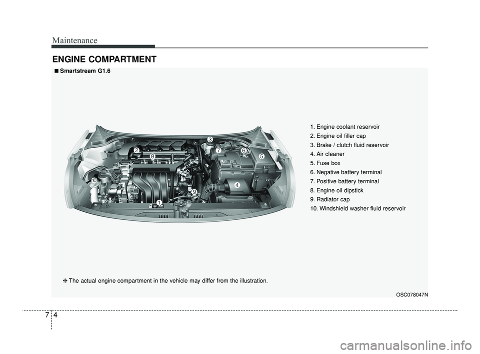
ENGINE COMPARTMENT
OSC078047N
■ ■Smartstream G1.6❈ The actual engine compartment in the vehicle may differ from the illustration. 1. Engine coolant reservoir
2. Engine oil filler cap
3. Brake / clutch fluid reservoir
4. Air cleaner
5. Fuse box
6. Negative battery terminal
7. Positive battery terminal
8. Engine oil dipstick
9. Radiator cap
10. Windshield washer fluid reservoir
SC PE USA 7.qxp 10/23/2020 6:05 PM Page 4
Page 449 of 534
757
Maintenance
FUSES
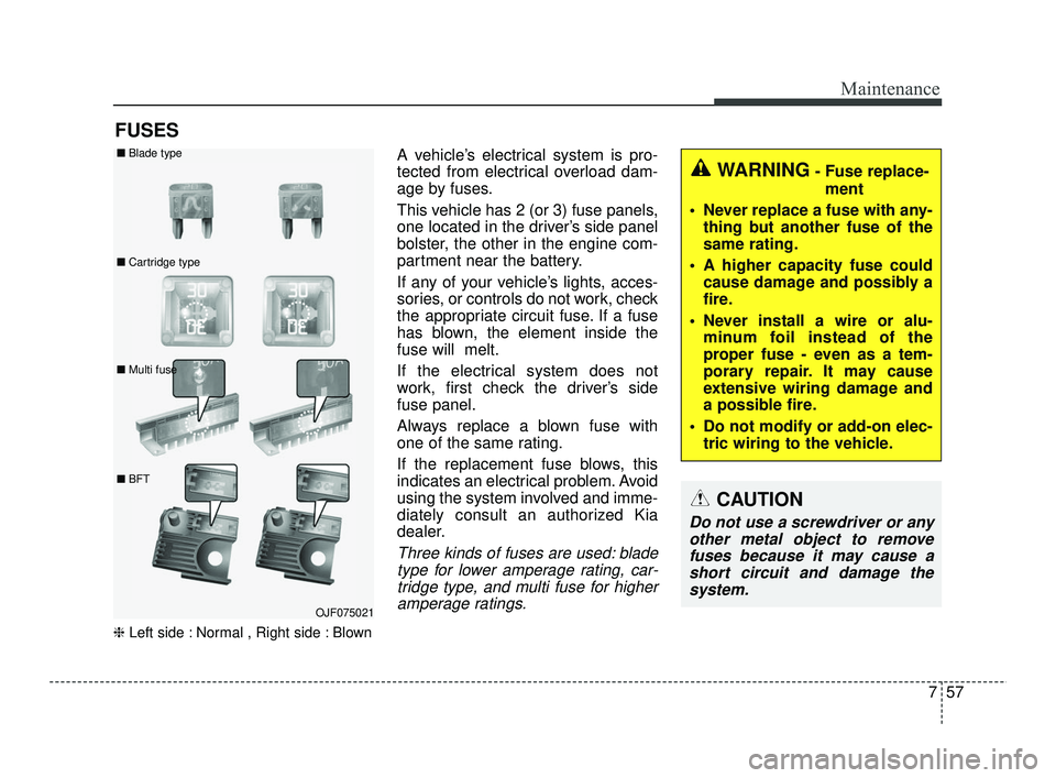
❈Left side : Normal , Right side : Blown
A vehicle’s electrical system is pro-
tected from electrical overload dam-
age by fuses.
This vehicle has 2 (or 3) fuse panels,
one located in the driver’s side panel
bolster, the other in the engine com-
partment near the battery.
If any of your vehicle’s lights, acces-
sories, or controls do not work, check
the appropriate circuit fuse. If a fuse
has blown, the element inside the
fuse will melt.
If the electrical system does not
work, first check the driver’s side
fuse panel.
Always replace a blown fuse with
one of the same rating.
If the replacement fuse blows, this
indicates an electrical problem. Avoid
using the system involved and imme-
diately consult an authorized Kia
dealer.
Three kinds of fuses are used: blade
type for lower amperage rating, car-tridge type, and multi fuse for higheramperage ratings.
WARNING- Fuse replace-
ment
Never replace a fuse with any- thing but another fuse of the
same rating.
A higher capacity fuse could cause damage and possibly a
fire.
Never install a wire or alu- minum foil instead of the
proper fuse - even as a tem-
porary repair. It may cause
extensive wiring damage and
a possible fire.
Do not modify or add-on elec- tric wiring to the vehicle.
CAUTION
Do not use a screwdriver or anyother metal object to removefuses because it may cause ashort circuit and damage thesystem.
OJF075021
■
Blade type
■ Cartridge type
■ Multi fuse
■ BFT
SC PE USA 7.qxp 10/23/2020 6:06 PM Page 57
Page 450 of 534
Maintenance
58
7
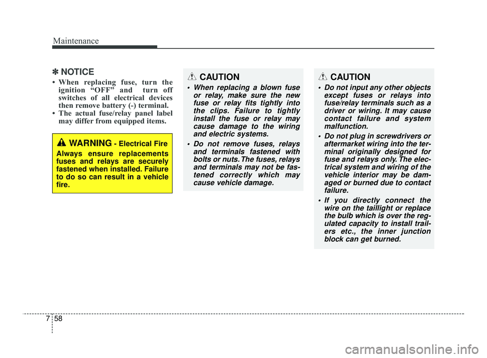
✽ ✽
NOTICE
• When replacing fuse, turn the
ignition “OFF” and turn off
switches of all electrical devices
then remove battery (-) terminal.
• The actual fuse/relay panel label may differ from equipped items.
WARNING- Electrical Fire
Always ensure replacements
fuses and relays are securely
fastened when installed. Failure
to do so can result in a vehicle
fire.
CAUTION
When replacing a blown fuse or relay, make sure the newfuse or relay fits tightly intothe clips. Failure to tightlyinstall the fuse or relay maycause damage to the wiringand electric systems.
Do not remove fuses, relays and terminals fastened withbolts or nuts. The fuses, relaysand terminals may not be fas-tened correctly which maycause vehicle damage.
CAUTION
Do not input any other objects except fuses or relays intofuse/relay terminals such as adriver or wiring. It may causecontact failure and systemmalfunction.
Do not plug in screwdrivers or aftermarket wiring into the ter-minal originally designed forfuse and relays only. The elec-trical system and wiring of thevehicle interior may be dam-aged or burned due to contactfailure.
If you directly connect the wire on the taillight or replacethe bulb which is over the reg-ulated capacity to install trail-ers etc., the inner junctionblock can get burned.
SC PE USA 7.qxp 10/23/2020 6:06 PM Page 58