engine KIA RIO HATCHBACK 2014 Owners Manual
[x] Cancel search | Manufacturer: KIA, Model Year: 2014, Model line: RIO HATCHBACK, Model: KIA RIO HATCHBACK 2014Pages: 446, PDF Size: 12.98 MB
Page 371 of 446
741
Maintenance
Battery recharging
Your vehicle has a maintenance-free,
calcium-based battery.
If the battery becomes dischargedin a short time (because, for exam-
ple, the headlights or interior lights
were left on while the vehicle was
not in use), recharge it by slow
charging (trickle) for 10 hours.
If the battery gradually discharges because of high electric load while
the vehicle is being used, recharge
it at no more than 20-30A for two
hours. When recharging the battery,
observe the following precautions:
The battery must be removed from
the vehicle and placed in an area
with good ventilation.
Watch the battery during charging, and stop or reduce the charging
rate if the battery cells begin
gassing (boiling) violently or if the
temperature of the electrolyte of
any cell exceeds 120°F (49°C).
Wear eye protection when check- ing the battery during charging.
Disconnect the battery charger in the following order.
1. Turn off the battery charger main switch.
2. Unhook the negative clamp from the negative battery terminal.
3. Unhook the positive clamp from the positive battery terminal.
Before performing maintenance or recharging the battery, turn off all
accessories and stop the engine.
The negative battery cable must be removed first and installed last
when the battery is disconnected.
Reset items
Items should be reset after the bat-
tery has been discharged or the bat-
tery has been disconnected.
Auto down window (See section 4)
Sunroof (See section 4)
Trip computer (See section 4)
Climate control system (See section 4)
Clock (See section 4)
Audio (See section 4)
Page 386 of 446
Maintenance
56
7
FUSES
A vehicle’s electrical system is pro-
tected from electrical overload dam-
age by fuses. This vehicle has 2 fuse panels, one
located in the driver’s side panel bol-
ster, the other in the engine compart-
ment near the battery.
If any of your vehicle’s lights, acces-
sories, or controls do not work, check
the appropriate circuit fuse. If a fuse
has blown, the element inside the
fuse will melt.
If the electrical system does not
work, first check the driver’s side
fuse panel.
Before replacing a blown fuse, move
to safe place, turn off the engine and
all electric devices, and then discon-
nect the negative battery cable.
Always replace a blown fuse with
one of the same rating.
If the replacement fuse blows, this
indicates an electrical problem. Avoid
using the system involved and imme-
diately consult an authorized Kia
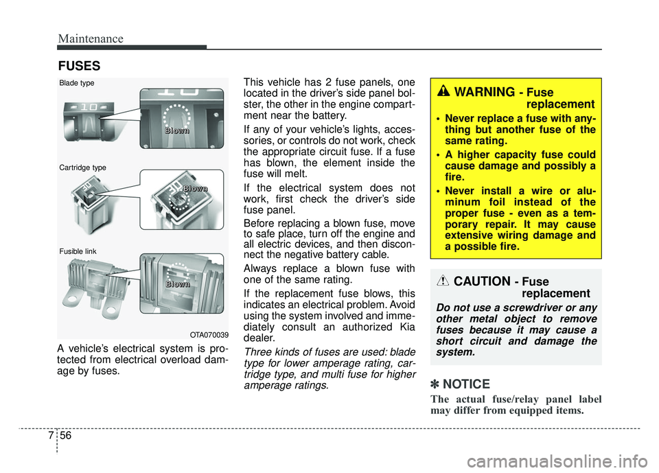
dealer.Three kinds of fuses are used: blade
type for lower amperage rating, car-tridge type, and multi fuse for higheramperage ratings.
✽ ✽ NOTICE
The actual fuse/relay panel label
may differ from equipped items.
WARNING - Fuse
replacement
Never replace a fuse with any-
thing but another fuse of the
same rating.
A higher capacity fuse could cause damage and possibly a
fire.
Never install a wire or alu- minum foil instead of the
proper fuse - even as a tem-
porary repair. It may cause
extensive wiring damage and
a possible fire.
OTA070039
Blade type
Cartridge type
Fusible link B B
B
B
l
l
l
l
o
o
o
o
w
w
w
w
n
n
n
n
B
B
B
B
l
l
l
l
o
o
o
o
w
w
w
w
n
n
n
n
B
B
B
B
l
l
l
l
o
o
o
o
w
w
w
w
n
n
n
n
CAUTION - Fuse
replacement
Do not use a screwdriver or any
other metal object to removefuses because it may cause ashort circuit and damage thesystem.
Page 387 of 446
757
Maintenance
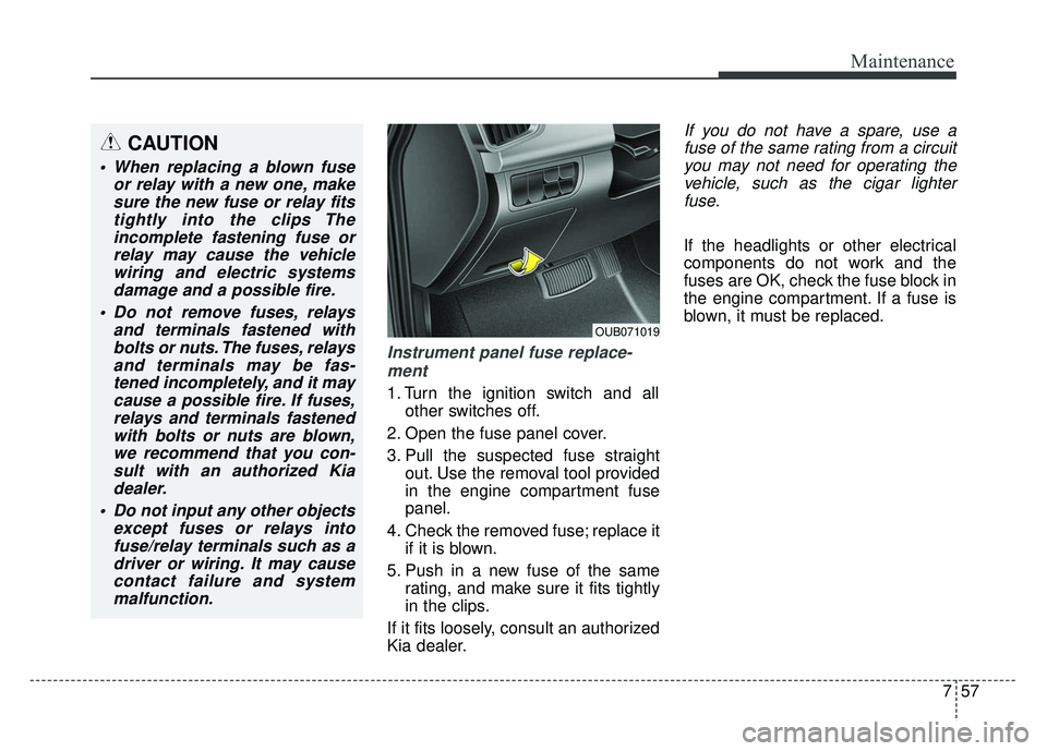
Instrument panel fuse replace-ment
1. Turn the ignition switch and all other switches off.
2. Open the fuse panel cover.
3. Pull the suspected fuse straight out. Use the removal tool provided
in the engine compartment fuse
panel.
4. Check the removed fuse; replace it if it is blown.
5. Push in a new fuse of the same rating, and make sure it fits tightly
in the clips.
If it fits loosely, consult an authorized
Kia dealer.
If you do not have a spare, use a fuse of the same rating from a circuityou may not need for operating thevehicle, such as the cigar lighterfuse.
If the headlights or other electrical
components do not work and the
fuses are OK, check the fuse block in
the engine compartment. If a fuse is
blown, it must be replaced.
OUB071019
CAUTION
When replacing a blown fuse or relay with a new one, makesure the new fuse or relay fitstightly into the clips Theincomplete fastening fuse orrelay may cause the vehiclewiring and electric systemsdamage and a possible fire.
Do not remove fuses, relays and terminals fastened withbolts or nuts. The fuses, relaysand terminals may be fas-tened incompletely, and it maycause a possible fire. If fuses,relays and terminals fastenedwith bolts or nuts are blown,we recommend that you con-sult with an authorized Kiadealer.
Do not input any other objects except fuses or relays intofuse/relay terminals such as adriver or wiring. It may causecontact failure and systemmalfunction.
Page 388 of 446
Maintenance
58
7
Memory fuse
Your vehicle is equipped with the
memory fuse to prevent battery dis-
charge if your vehicle is parked with-
out being operated for prolonged
periods. Use the following proce-
dures before parking the vehicle for
prolonged periods.
1. Turn off the engine.
2. Turn off the headlights and tail
lights.
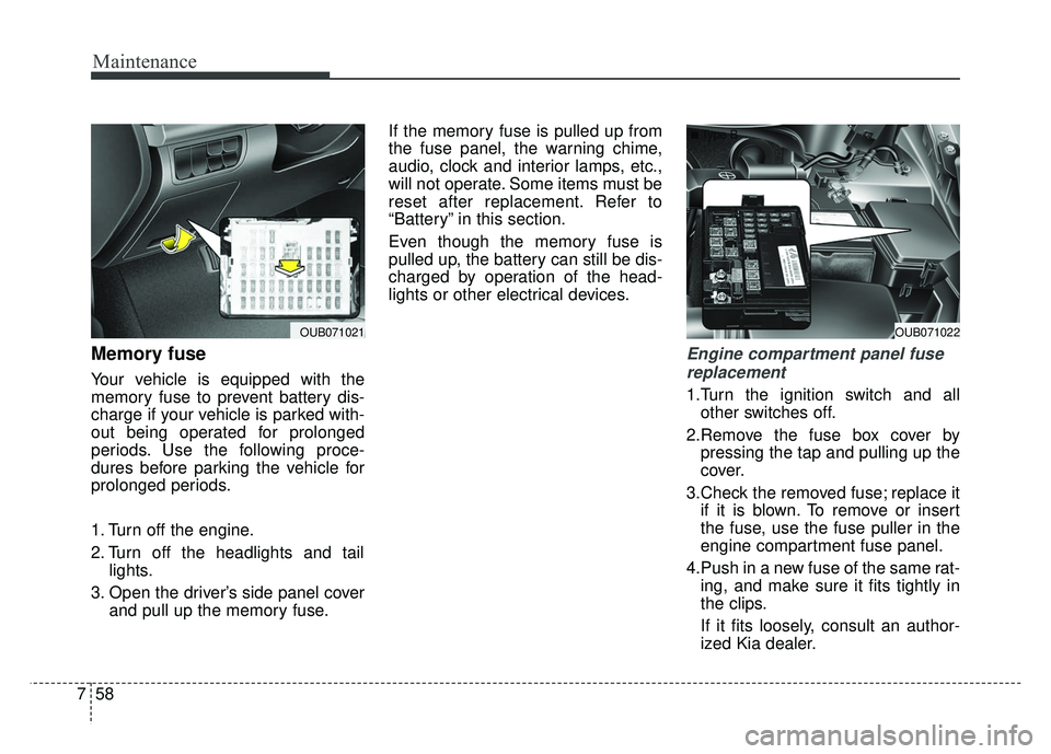
3. Open the driver’s side panel cover and pull up the memory fuse. If the memory fuse is pulled up from
the fuse panel, the warning chime,
audio, clock and interior lamps, etc.,
will not operate. Some items must be
reset after replacement. Refer to
“Battery” in this section.
Even though the memory fuse is
pulled up, the battery can still be dis-
charged by operation of the head-
lights or other electrical devices.
Engine compartment panel fuse
replacement
1.Turn the ignition switch and all other switches off.
2.Remove the fuse box cover by pressing the tap and pulling up the
cover.
3.Check the removed fuse; replace it if it is blown. To remove or insert
the fuse, use the fuse puller in the
engine compartment fuse panel.
4.Push in a new fuse of the same rat- ing, and make sure it fits tightly in
the clips.
If it fits loosely, consult an author-
ized Kia dealer.
OUB071022
■Type B
OUB071021
Page 389 of 446
759
Maintenance
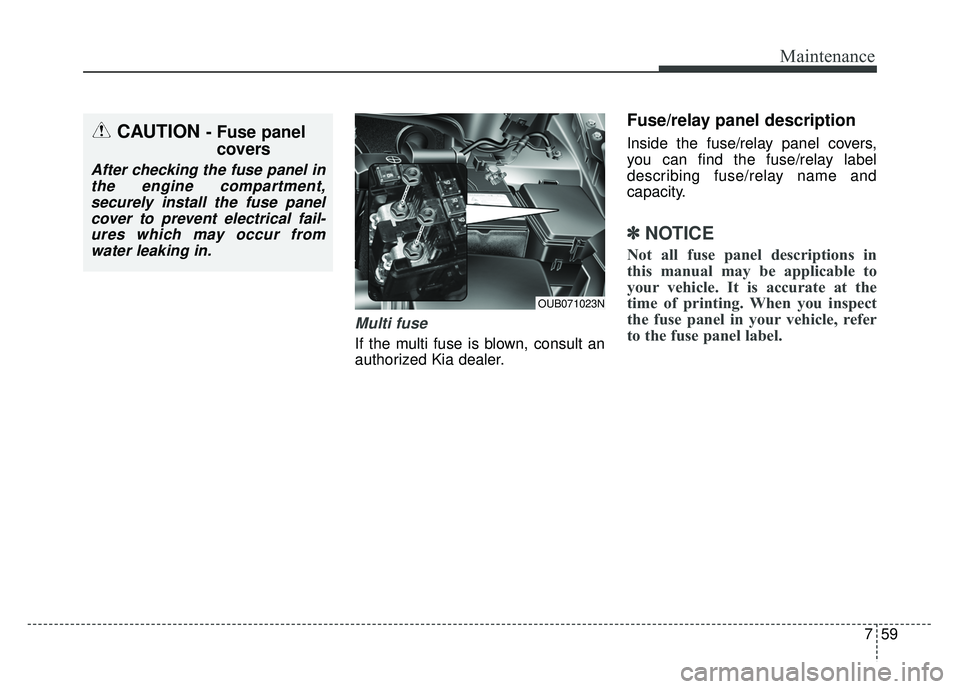
Multi fuse
If the multi fuse is blown, consult an
authorized Kia dealer.
Fuse/relay panel description
Inside the fuse/relay panel covers,
you can find the fuse/relay label
describing fuse/relay name and
capacity.
✽ ✽NOTICE
Not all fuse panel descriptions in
this manual may be applicable to
your vehicle. It is accurate at the
time of printing. When you inspect
the fuse panel in your vehicle, refer
to the fuse panel label.
OUB071023N
CAUTION - Fuse panel
covers
After checking the fuse panel in
the engine compartment,securely install the fuse panelcover to prevent electrical fail-ures which may occur fromwater leaking in.
Page 391 of 446
761
Maintenance
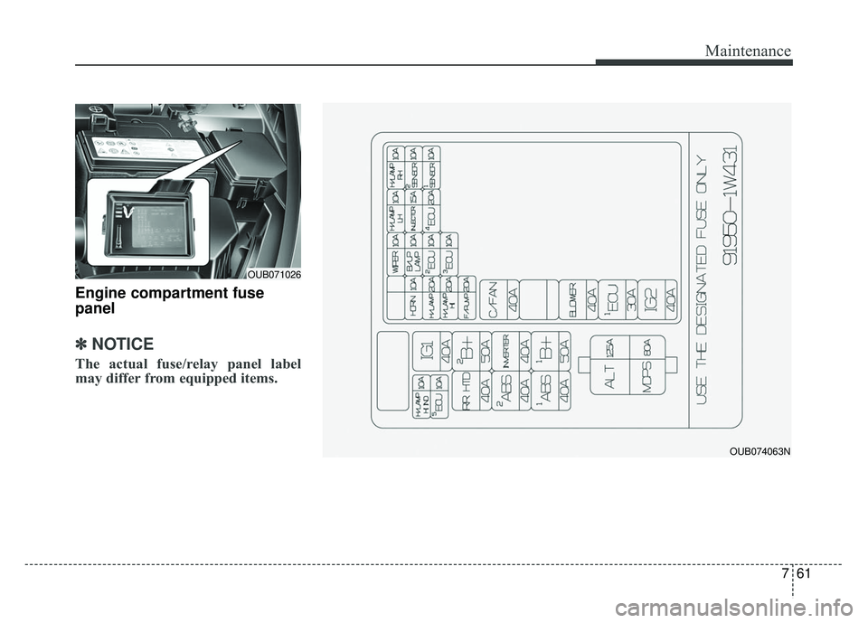
Engine compartment fuse
panel
✽ ✽NOTICE
The actual fuse/relay panel label
may differ from equipped items.
OUB074063N
OUB071026
Page 395 of 446
765
Maintenance
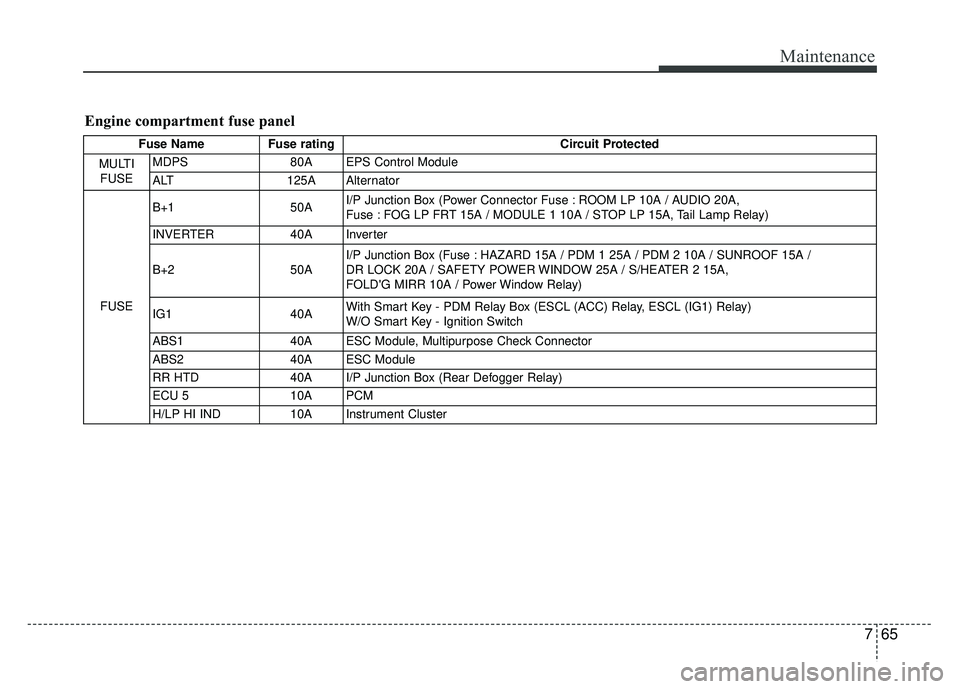
Engine compartment fuse panel
Fuse NameFuse rating Circuit Protected
MULTI FUSE MDPS
80A EPS Control Module
ALT 125A Alternator
FUSE B+1
50AI/P Junction Box (Power Connector Fuse : ROOM LP 10A / AUDIO 20A,
Fuse : FOG LP FRT 15A / MODULE 1 10A / STOP LP 15A, Tail Lamp Relay)
INVERTER 40A Inverter
B+2 50AI/P Junction Box (Fuse : HAZARD 15A / PDM 1 25A / PDM 2 10A / SUNROOF 15A /
DR LOCK 20A / SAFETY POWER WINDOW 25A / S/HEATER 2 15A,
FOLD'G MIRR 10A / Power Window Relay)
IG1 40AWith Smart Key - PDM Relay Box (ESCL (ACC) Relay, ESCL (IG1) Relay)
W/O Smart Key - Ignition Switch
ABS1 40A ESC Module, Multipurpose Check Connector
ABS2 40A ESC Module
RR HTD 40A I/P Junction Box (Rear Defogger Relay)
ECU 5 10A PCM
H/LP HI IND 10A Instrument Cluster
Page 396 of 446
Maintenance
66
7
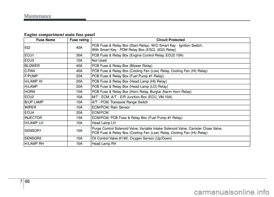
Engine compartment main fuse panel
Fuse Name Fuse rating Circuit Protected
IG2 40APCB Fuse & Relay Box (Start Relay), W/O Smart Key - Ignition Switch,
With Smart Key - PDM Relay Box (ESCL (IG2) Relay)
ECU1 30A PCB Fuse & Relay Box (Engine Control Relay, ECU2 10A)
ECU3 10A Not Used
BLOWER 40A PCB Fuse & Relay Box (Blower Relay)
C/FAN 40A PCB Fuse & Relay Box (Cooling Fan (Low) Relay, Cooling Fan (Hi) Relay)
F/PUMP 20A PCB Fuse & Relay Box (Fuel Pump #1 Relay)
H/LAMP HI 20A PCB Fuse & Relay Box (Head Lamp (HI) Relay)
H/LAMP 20A PCB Fuse & Relay Box (Head Lamp (LO) Relay)
HORN 10A PCB Fuse & Relay Box (Horn Relay, Burglar Alarm Horn Relay)
ECU2 10A M/T - ECM, A/T - E/R Junction Box (ECU_VM 10A)
B/UP LAMP 10A A/T - PCM, Transaxle Range Switch
WIPER 10A ECM/PCM, Rain Sensor
ECU4 20A ECM/PCM
INJECTOR 15A ECM/PCM, PCB Fuse & Relay Box (Fuel Pump #1 Relay)
H/LAMP LH 10A Head Lamp LH
SENSOR1 10APurge Control Solenoid Valve, Variable Intake Solenoid Valve, Canister Close Valve,
PCB Fuse & Relay Box (Cooling Fan (Low) Relay, Cooling Fan (Hi) Relay)
SENSOR2 10A Oil Control Valve #1/#2, Oxygen Sensor (Up/Down)
H/LAMP RH 10A Head Lamp RH
Page 399 of 446
769
Maintenance
Always handle them carefully, and
avoid scratches and abrasions. If the
bulbs are lit, avoid contact with liq-
uids. Never touch the glass with bare
hands. Residual oil may cause the
bulb to overheat and burst when lit. A
bulb should be operated only when
installed in a headlight.
If a bulb becomes damaged or
cracked, replace it immediately and
carefully dispose of it.
Wear eye protection when changing
a bulb. Allow the bulb to cool down
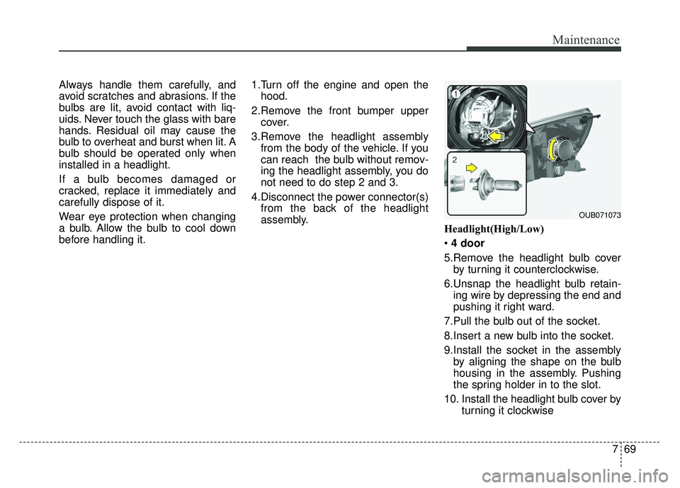
before handling it.1.Turn off the engine and open the
hood.
2.Remove the front bumper upper cover.
3.Remove the headlight assembly from the body of the vehicle. If you
can reach the bulb without remov-
ing the headlight assembly, you do
not need to do step 2 and 3.
4.Disconnect the power connector(s) from the back of the headlight
assembly. Headlight(High/Low)
4 door
5.Remove the headlight bulb cover by turning it counterclockwise.
6.Unsnap the headlight bulb retain- ing wire by depressing the end and
pushing it right ward.
7.Pull the bulb out of the socket.
8.Insert a new bulb into the socket.
9.Install the socket in the assembly by aligning the shape on the bulb
housing in the assembly. Pushing
the spring holder in to the slot.
10. Install the headlight bulb cover by turning it clockwise
OUB071073
Page 404 of 446
Maintenance
74
7
Outside light
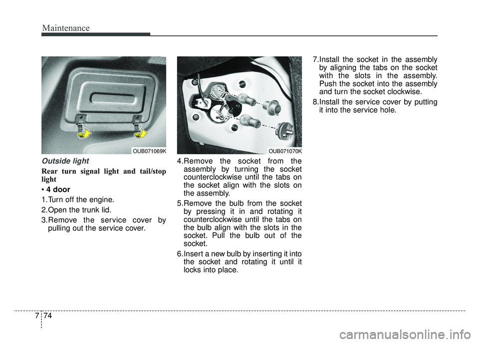
Rear turn signal light and tail/stop
light
4 door
1.Turn off the engine.
2.Open the trunk lid.
3.Remove the service cover by pulling out the service cover. 4.Remove the socket from the
assembly by turning the socket
counterclockwise until the tabs on
the socket align with the slots on
the assembly.
5.Remove the bulb from the socket by pressing it in and rotating it
counterclockwise until the tabs on
the bulb align with the slots in the
socket. Pull the bulb out of the
socket.
6.Insert a new bulb by inserting it into the socket and rotating it until it
locks into place. 7.Install the socket in the assembly
by aligning the tabs on the socket
with the slots in the assembly.
Push the socket into the assembly
and turn the socket clockwise.
8.Install the service cover by putting it into the service hole.
OUB071070KOUB071069K