Audio KIA Sorento 2006 1.G Owner's Manual
[x] Cancel search | Manufacturer: KIA, Model Year: 2006, Model line: Sorento, Model: KIA Sorento 2006 1.GPages: 312, PDF Size: 5.21 MB
Page 2 of 312
Thank you for choosing a Kia vehicle.
When you require service, remember that your dealer
knows your vehicle best. Your dealer has factory-trained
technicians, recommended special tools, genuine Kia
replacement parts and is dedicated to your complete
satisfaction.
Because subsequent owners require this important
information as well, this publication should remain with
the vehicle if it is sold.
This manual will familiarize you with operational, main-
tenance and safety information about your new vehicle.
It is supplemented by a Warranty & Consumer
Information Manual that provides important information
on all warranties regarding your vehicle. If your vehicle is
equipped with an audio system, you will also receive a
Kia Integrated Audio System Manual. We urge you to
read these manuals carefully.
Kia offers a great variety of options, components and
features for its various models.Therefore, the equipment described in this manual,
along with the various illustrations, may not all be appli-
cable to your particular vehicle. The information and
specifications provided in this manual were accurate at
the time of printing. Kia reserves the right to discontinue
or change specifications or design at any time without
notice and without incurring any obligation. If you have
questions, always check with your Kia Dealer.
We assure you of our continuing interest in your motor-
ing pleasure and satisfaction in your Kia vehicle.
© 2005 Kia Motors Corp.
All rights reserved. Reproduction by any means, elec-
tronic or mechanical, including photocopying, recording,
or by any information storage and retrieval system or
translation in whole or part is not permitted without writ-
ten authorization from Kia Motors Corporation.
Printed in KoreaFOREWORDi
BL-ENG (CAN)-foreword.qxd 8/8/2005 10:40 AM Page 2
Page 74 of 312
When repairing or scrapping the
vehicles
Repairing steering wheel, instru-
ment panel, center console or
roofs, or installing car audio around
center console or painting front
metal sheet could disable the
airbag system. Have them checked
by an authorized Kia dealer.
When leaving the vehicle at an
authorized Kia dealer, inform that
the vehicle is equipped with airbag
system, and leave the owner’s
manual in the vehicle.
Since airbag system contains
explosive chemical substances,
contact an authorized Kia dealer
when scrapping the vehicle.
KNOWING YOUR VEHICLE
3-65
CAUTION
Do not modify any part of the
Supplemental Restraint System.
Excessive modification could
make the airbag system ineffec-
tive.
WARNING
Do not modify your steering
wheel, seat or any other part
of the Supplemental Restraint
System. Modification could
make the system inoperable.
Do not work on the system’s
components or wiring. This
could cause the airbags to
inflate inadvertently, possibly
seriously injuring someone.
Working on the system could
also disable the system so
that the airbags would not
deploy in a collision.
Any work on the SRS system,
such as removing, installing,
repairing, or any work on the
steering wheel must be per-
formed by a qualified Kia
technician. Improper handling
of the airbag system may
result in serious personal
injury.
BL-ENG (CAN)-3.qxd 7/28/05 5:52 PM Page 65
Page 91 of 312
ELECTRICAL POWER
OUTLET (IF EQUIPPED)
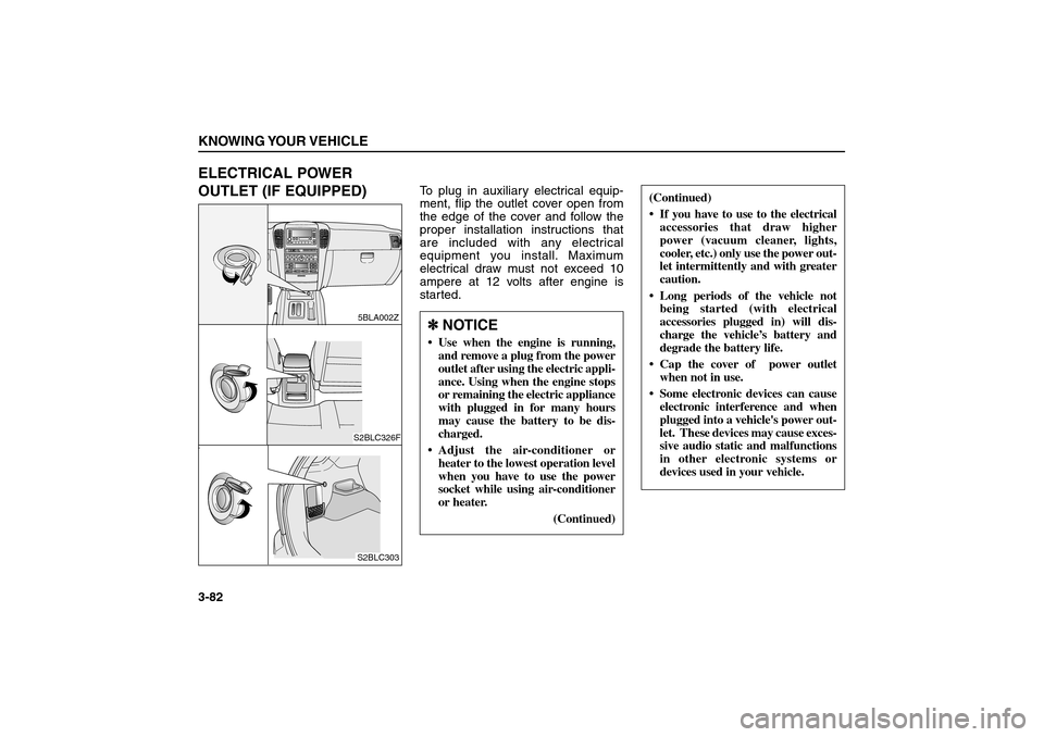
To plug in auxiliary electrical equip-
ment, flip the outlet cover open from
the edge of the cover and follow the
proper installation instructions that
are included with any electrical
equipment you install. Maximum
electrical draw must not exceed 10
ampere at 12 volts after engine is
started.
KNOWING YOUR VEHICLE3-82
P
R
N
D2LH
M
5BLA002ZS2BLC326FS2BLC303
(Continued)
If you have to use to the electrical
accessories that draw higher
power (vacuum cleaner, lights,
cooler, etc.) only use the power out-
let intermittently and with greater
caution.
Long periods of the vehicle not
being started (with electrical
accessories plugged in) will dis-
charge the vehicle’s battery and
degrade the battery life.
Cap the cover of power outlet
when not in use.
Some electronic devices can cause
electronic interference and when
plugged into a vehicle's power out-
let. These devices may cause exces-
sive audio static and malfunctions
in other electronic systems or
devices used in your vehicle.
✽ ✽
NOTICE Use when the engine is running,
and remove a plug from the power
outlet after using the electric appli-
ance. Using when the engine stops
or remaining the electric appliance
with plugged in for many hours
may cause the battery to be dis-
charged.
Adjust the air-conditioner or
heater to the lowest operation level
when you have to use the power
socket while using air-conditioner
or heater.
(Continued)
BL-ENG (CAN)-3.qxd 7/28/05 5:52 PM Page 82
Page 242 of 312
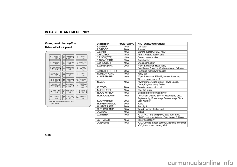
Fuse panel description
Driver-side kick panelIN CASE OF AN EMERGENCY6-10
( )
( ) (
) ( ) ( )
( )
W/SHD
15AS/ROOF
20A
( )PREMIUM
AUDIO30A
( )S/WARMER20A
(
)
O/S MIRROR10A
(
)
RELAY COIL10ASTART
10A
METER
10AENGINE
10A HAZARD
15AP/SCK(CTR)
15A
CIGAR (FRT)
15A
DRL/OBD-II10AWIPER(FRT)
20A
TCCS
20AROOM LAMP10A FOG (RR)
15AP/SCK
(FRT,RR)
30ASTOP LAMP
20ATURN LAMP
10A
A/BAG
10A
( )TRAILER15A WIPER(RR)
10AACC
10A
22 23 24 19 20 21
16 17 18
13 14 15 10 11 12789 456 123USE THE DESIGNATED FUSES ONLY.
*( ) IS OPTION.
Description FUSE RATING PROTECTED OMPONENT
1. W/SHD 15 A Defroster
2. S/ROOF 20 A Sunroof
3. START 10 A Starting system, PCM, ACC
4. HAZARD 15 A Turn & Hazard flasher unit
5. P/SCK(CTR) 15 A Center power socket
6. CIGAR (FRT) 15 A Cigar lighter
7. DRL/OBD-II 10 A Check connector
8. WIPER (FRT) 20 A Wiper & Washer, Head light,
Front
heater & Aircon, Cooling system, Defroster
9. P/SCK (FRT, RR) 30 A Front and rear power socket
10. RELAY COIL 10 A Relay coil
11. WIPER (RR) 10 A Wiper & Washer, ETWIS, Heater & Aircon,
Trip computer, sunroof
12. ACC 10 A Power mirror, Cigar lighter, Power Socket,
Clock, Keyless entry, Audio
13. TCCS 20 A Transfer case control unit
14. FOG (RR) 15 A Rear fog lamp
15. O/S MIRROR 10 A Electric remote control mirror
16. ROOM LAMP 10 A Instrument cluster, ETWIS, Head light, DRL,
Keyless entry, Room lamp, Sunvior lamp, Clock
17. S/WARMER 20 A Seat warmer
18.
PREMIUM AUDIO
30 A Audio
19. STOP LAMP 20 A Stop light
20. TURN LAMP 10 A Turn & Hazard flasher unit
21. A/BAG 10 A Airbag
22. METER 10 A PCM, ACC, Trip computer, Stop light ,DRL,
ETWIS, Instrument cluster, Front heater & Aircon
23. TRAILER 15 A Trailer accessory
24. ENGINE 10 APCM, Cooling, Speed sensor, Diagnosis connector,
ACC, Instrument cluster, ABS
BL-ENG (CAN)-6.qxd 7/28/05 5:57 PM Page 10
Page 243 of 312
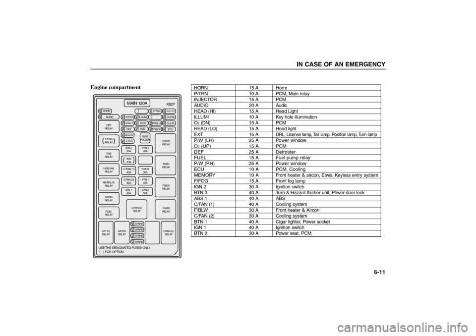
Engine compartment
IN CASE OF AN EMERGENCY
6-11
( )MAIN 120A
HORN20A15A 15A 25A
15A10A 15A 10A 10A 25A 25A
15A 15A 15A 15A 10A
AUDIO
HEAD(HI)
HEAD(LO)
INJECTOR
DEF25A 20A 15A 10ASPARE
SPARE
SPARE
SPARE
MEMORY15A(F/FOG)
ILLUMIP/TRN
P/W(LH)O
2(DN)
O2(UP)
P/W(RH) ECU (EXT)
FUEL
FUSE
PULLER
START
RELAY
MAIN
RELAY
F/BLW
RELAY
P/WIN
RELAY
C/FAN (L)
RELAY A/CON
RELAY
USE THE DESIGNATED FUSES ONLY.
*( ) FOR OPTION.
K52Y
C/F (H)
RELAYC/FAN (2)
RELAY
FUEL
RELAYHORN
RELAY HEAD(LO)
RELAY HEAD(HI)
RELAYTNS
RELAYDEF
RELAY
F/FOG
RELAY
IGN 2
30ABTN 3
40A
ABS
40A
C /FAN (1)
40AF/BLW
30A
C/FAN (2)
30ABTN 1
40A
IGN 1
40ABTN 2
30A( )
( )
HORN 15 A Horm
P/TRN 10 A PCM, Main relay
INJECTOR 15 A PCM
AUDIO 20 A Audio
HEAD (HI) 15 A Head Light
ILLUMI 10 A Key hole illumination
O2(DN) 15 A PCM
HEAD (LO) 15 A Head light
EXT 15 A
DRL, License lamp, Tail lamp, Position lamp, Turn lamp
P/W (LH) 25 A Power window
O2(UP) 15 A PCM
DEF 25 A Defroster
FUEL 15 A Fuel pump relay
P/W (RH) 25 A Power window
ECU 10 A PCM, Cooling
MEMORY 10 A Front heater & aircon, Etwis, Keyless entry system
F/FOG 15 A Front fog lamp
IGN 2 30 A Ignition switch
BTN 3 40 A Turn & Hazard flasher unit, Power door lock
ABS 1 40 A ABS
C/FAN (1) 40 A Cooling system
F/BLW 30 A Front heater & Aircon
C/FAN (2) 30 A Cooling system
BTN 1 40 A Cigar lighter, Power socket
IGN 1 40 A Ignition switch
BTN 2 30 A Power seat, PCM
BL-ENG (CAN)-6.qxd 7/28/05 5:57 PM Page 11
Page 244 of 312
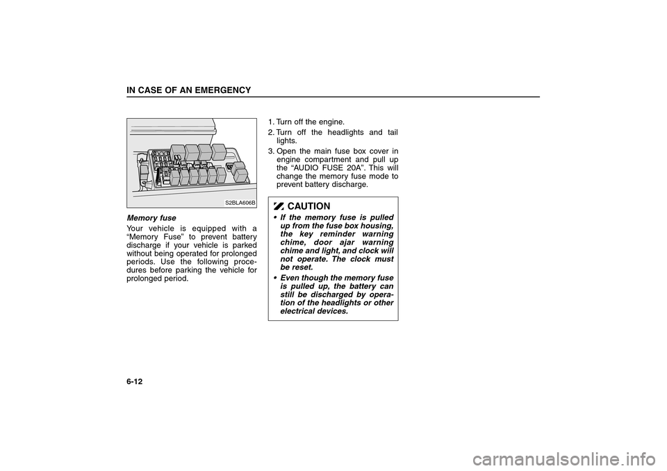
Memory fuse
Your vehicle is equipped with a
“Memory Fuse”to prevent battery
discharge if your vehicle is parked
without being operated for prolonged
periods. Use the following proce-
dures before parking the vehicle for
prolonged period.1. Turn off the engine.
2. Turn off the headlights and tail
lights.
3. Open the main fuse box cover in
engine compartment and pull up
the “AUDIO FUSE 20A”. This will
change the memory fuse mode to
prevent battery discharge.IN CASE OF AN EMERGENCY6-12
S2BLA606B
CAUTION
• If the memory fuse is pulled
up from the fuse box housing,
the key reminder warning
chime, door ajar warning
chime and light, and clock will
not operate. The clock must
be reset.
Even though the memory fuse
is pulled up, the battery can
still be discharged by opera-
tion of the headlights or other
electrical devices.
BL-ENG (CAN)-6.qxd 7/28/05 5:57 PM Page 12