turn signal KIA Sorento 2017 3.G Owner's Manual
[x] Cancel search | Manufacturer: KIA, Model Year: 2017, Model line: Sorento, Model: KIA Sorento 2017 3.GPages: 576, PDF Size: 7.82 MB
Page 62 of 576
345
Safety features of your vehicle
How does the air bag system
operate?
Air bags are activated (able toinflate if necessary) only when the
ignition switch is turned to the ON
or START position.
The appropriate air bags inflate instantly in the event of a serious
frontal collision or side collision in
order to help protect the occupants
from serious physical injury.
There is no single speed at which the air bags will inflate.
Generally, air bags are designed to
inflate based upon the severity of a
collision and its direction. These
two factors determine whether the
sensors produce an electronic
deployment/ inflation signal.
Air bag deployment depends on a number of factors including vehicle
speed, angles of impact and the
density and stiffness of the vehi-
cles or objects which your vehicle
hits in the collision. The determin-
ing factors are not limited to those
mentioned above. The front air bags will completely
inflate and deflate in an instant.
It is virtually impossible for you to
see the air bags inflate during an
accident.
It is much more likely that you will
simply see the deflated air bags
hanging out of their storage com-
partments after the collision.
In addition to inflating in serious side collisions, side and/or curtain
air bags will inflate if the sensing
system detects a rollover.
When a rollover is detected, side and/or curtain air bags will remain
inflated longer to help provide pro-
tection from ejection, especially
when used in conjunction with the
seat belts. In order to help provide protection,
the air bags must inflate rapidly.
The speed of the air bag inflation is
a consequence of extremely short
time in which to inflate the air bag
between the occupant and the
vehicle structures before the occu-
pant impacts those structures. This
speed of inflation reduces the risk
of serious or life-threatening
injuries and is thus a necessary
part of the air bag design.
However, air bag inflation can also
cause injuries which can include
facial abrasions, bruises and bro-
ken bones because the inflation
speed also causes the air bags to
expand with a great deal of force.
There are even circumstances under which contact with the
steering wheel or passenger air
bag can cause fatal injuries,
especially if the occupant is
positioned excessively close to
the steering wheel or passenger
air bag.
Page 87 of 576
Steering wheel . . . . . . . . . . . . . . . . . . . . . . . . . . . . . 4-55
• Electric power steering (EPS) . . . . . . . . . . . . . . . . . . 4-55
• Tilt and telescopic steering . . . . . . . . . . . . . . . . . . . . 4-56
• Heated steering wheel . . . . . . . . . . . . . . . . . . . . . . . . . 4-57
• Horn . . . . . . . . . . . . . . . . . . . . . . . . . . . . . . . . . . . . \
. . . 4-57
Mirrors . . . . . . . . . . . . . . . . . . . . . . . . . . . . . . . . . . 4-59\
• Inside rearview mirror . . . . . . . . . . . . . . . . . . . . . . . . 4-59
• Outside rearview mirror. . . . . . . . . . . . . . . . . . . . . . . 4-69
Instrument cluster . . . . . . . . . . . . . . . . . . . . . . . . . 4-73
• Instrument cluster control . . . . . . . . . . . . . . . . . . . . . 4-74
• LCD display control . . . . . . . . . . . . . . . . . . . . . . . . . . 4-74
• Gauges . . . . . . . . . . . . . . . . . . . . . . . . . . . . . . . . . . . . \
. 4-75
• Transaxle shift indicator . . . . . . . . . . . . . . . . . . . . . . . 4-78
• Icy Road Warning Indicator . . . . . . . . . . . . . . . . . . . 4-78
LCD display . . . . . . . . . . . . . . . . . . . . . . . . . . . . . . 4-79
• LCD modes. . . . . . . . . . . . . . . . . . . . . . . . . . . . . . . . . .\
4-79
Trip modes (trip computer). . . . . . . . . . . . . . . . . . 4-80
• Trip Modes . . . . . . . . . . . . . . . . . . . . . . . . . . . . . . . . . . 4-80\
• Fuel Economy . . . . . . . . . . . . . . . . . . . . . . . . . . . . . . . 4-80
• Trip A/B . . . . . . . . . . . . . . . . . . . . . . . . . . . . . . . . . . . . \
4-82
• Digital speedometer . . . . . . . . . . . . . . . . . . . . . . . . . . . 4-83
• One time driving information mode . . . . . . . . . . . . . 4-83
• Turn by turn mode . . . . . . . . . . . . . . . . . . . . . . . . . . . 4-84
• ASCC/LDWS mode . . . . . . . . . . . . . . . . . . . . . . . . . . . 4-84
• A/V mode . . . . . . . . . . . . . . . . . . . . . . . . . . . . . . . . . . . 4-\
84• Service mode . . . . . . . . . . . . . . . . . . . . . . . . . . . . . . . . 4-85
• User settings mode. . . . . . . . . . . . . . . . . . . . . . . . . . . . 4-86
• Warning messages . . . . . . . . . . . . . . . . . . . . . . . . . . . . 4-90
Warning and indicator lights . . . . . . . . . . . . . . . . 4-97
• Warning lights . . . . . . . . . . . . . . . . . . . . . . . . . . . . . . . 4-97
• Indicator lights. . . . . . . . . . . . . . . . . . . . . . . . . . . . . . 4-105
Rear parking assist system . . . . . . . . . . . . . . . . . 4-109
• Operation of the rear parking assist system . . . . . . 4-109
• Non-operational conditions of
rear parking assist system . . . . . . . . . . . . . . . . . . . 4-110
• Rear parking assist system precautions . . . . . . . . . 4-111
• Self-diagnosis . . . . . . . . . . . . . . . . . . . . . . . . . . . . . . . 4-112
Rearview camera . . . . . . . . . . . . . . . . . . . . . . . . . 4-113
360° camera monitoring system . . . . . . . . . . . . . 4-114
Lighting . . . . . . . . . . . . . . . . . . . . . . . . . . . . . . . . . 4-115
• Battery saver function . . . . . . . . . . . . . . . . . . . . . . . . 4-115
• Daytime running light . . . . . . . . . . . . . . . . . . . . . . . . 4-115
• Lighting control . . . . . . . . . . . . . . . . . . . . . . . . . . . . . 4-115
• High beam operation . . . . . . . . . . . . . . . . . . . . . . . . . 4-117
• Turn signals and lane change signals. . . . . . . . . . . . 4-118
• Front fog light . . . . . . . . . . . . . . . . . . . . . . . . . . . . . . 4-119
• Check headlight . . . . . . . . . . . . . . . . . . . . . . . . . . . . 4-119
• Headlight leveling device . . . . . . . . . . . . . . . . . . . . . 4-120
• AFLS (Adaptive Front Lighting System) . . . . . . . . 4-120
4
Page 95 of 576
Features of your vehicle
10
4
To activate the immobilizer system:
Turn the ignition key to the OFF posi-
tion. The immobilizer system acti-
vates automatically. Without a valid
ignition key for your vehicle, the
engine will not start.
To deactivate the immobilizer
system:
Insert the ignition key into the key
cylinder and turn it to the ON position.
In order to prevent theft of your vehi-
cle, do not leave spare keys anywhere
in your vehicle. Your Immobilizer pass-
word is a customer unique password
and should be kept confidential. Do
not leave this number anywhere in
your vehicle.
✽ ✽ NOTICE
When starting the engine, do not use
the key with other immobilizer keys
around. Otherwise the engine may
not start or may stop soon after it
starts. Keep each key separate in
order to avoid a starting malfunction.
Do not put metal accessories near
the ignition switch.
Metal accessories may interrupt the
transponder signal and may prevent
the engine from being started.
✽ ✽NOTICE
If you need additional keys or lose
your keys, contact an authorized
Kia dealer.
CAUTION- Immobilizer
damage
Do not expose your immobilizersystem to moisture, static elec-tricity and rough handling. Thismay damage your immobilizer.
CAUTION- Immobilizer
alterations
Do not change, alter or adjustthe immobilizer system becauseit could cause the immobilizersystem to malfunction.
Page 152 of 576
467
Features of your vehicle
Rolling code programming
To train a garage door opener (or
other rolling code equipped devices)
with the rolling code feature, follow
these instructions after completing
the “Programming” portion of this
text. (A second person may make the
following training procedures quicker
& easier.)
4. Locate the “learn” or “smart” but-ton on the device’s motor head
unit. Exact location and color of
the button may vary by product
brand. If there is difficulty locating
the “learn” or “smart” button, refer-
ence the device’s owner’s manual
or contact HomeLink at 1-800-
355-3515 or on the internet at
www.homelink.com.
5. Press and release the “learn” or “smart” button on the device’s
motor head unit. You have 30 sec-
onds to complete step number 6. 6. Return to the vehicle and firmly
press and release the pro-
grammed HomeLink button up to
three times. The rolling code
equipped device should now rec-
ognize the HomeLink signal and
activate when the HomeLink but-
ton is pressed. The remaining two
buttons may now be programmed
if this has not previously been
done. Refer to the “Programming”
portion of this text. Operating HomeLink
To operate, simply press the
programmed HomeLink button.
Activation will now occur for the
trained product (garage door, securi-
ty system, entry door lock, estate
gate, or home or office lighting). For
convenience, the hand-held trans-
mitter of the device may also be used
at any time. The HomeLink Wireless
Controls System (once programmed)
or the original hand-held transmitter
may be used to activate the device
(e.g. garage door, entry door lock,
etc.). In the event that there are still
programming difficulties, contact
HomeLink at 1-800-355-3515 or on
the internet at www.homelink.com.
Page 173 of 576
Features of your vehicle
88
4
Two Press Unlock
Off:
The two press unlock function will
be deactivated. Therefore, all doors
will unlock if the door is unlocked.
On: The driver’s door will unlock if the
door is unlocked. When the door is
unlocked again within 4 seconds,
all doors will unlock.
Horn Feedback
Off: The Horn feedback operation will
be deactivated.
On: After locking the door by pressing
the lock button on the transmitter, if
you press the lock button again
within 4 seconds, the warning
sound will operate once to indicate
that all doors are locked. Power liftgate (if equipped)
If this item is checked, the power lift-
gate function will be activated.
Smart Power liftgate (if equipped)
If this item is checked, the smart
power liftgate function will be activat-
ed.Lights
One touch turn signal
If this item is checked, the lane
change signals will blink 3, 5 or 7
times when the turn signal lever is
moved slightly.
You can set the one touch turn
sginal function.
The One touch turn signal
function will be deactivated.
Head Lamp Delay (if equipped)
If this item is checked, the headlamp
delay function will be activated.
Welcome Light (if equipped)
If this item is checked, the welcome
light function of the pocket lamp will
be activated.
Page 191 of 576
Features of your vehicle
106
4
Immobilizer Indicator
Light (With Smart Key)
This indicator light illuminates for up
to 30 seconds:
When the vehicle detects the smart key in the vehicle properly
while the Engine Start/Stop Button
is ACC or ON.
- At this time, you can start theengine.
- The indicator light goes off after starting the engine.
This indicator light blinks for a few
seconds:
When the smart key is not in the vehicle.
- At this time, you can not start theengine. This indicator light illuminates for 2
seconds and goes off:
When the vehicle can not detect
the smart key which is in the vehi-
cle while the Engine Start/Stop
Button is ON.
In this case, have your vehicle
inspected by an authorized Kia
dealer.
This indicator light blinks:
When the battery of the smart key is weak.
- At this time, you can not start theengine. However, you can start
the engine if you press the Engine
Start/Stop Button with the smart
key. (For more details, refer to
“Starting the Engine” in section 5).
When there is a malfunction with the immobilizer system.
In this case, have your vehicle
inspected by an authorized Kia
dealer.
Turn Signal Indicator
Light
This indicator light blinks:
When you turn the turn signal light on.
If any of the following occurs, there
may be a malfunction with the turn
signal system. In this case, have your
vehicle inspected by an authorized
Kia dealer. - The indicator light does not blinkbut illuminates.
- The indicator light blinks more rapidly.
- The indicator light does not illumi- nate at all.
Page 192 of 576
4107
Features of your vehicle
High Beam IndicatorLight
This indicator light illuminates:
When the headlights are on and in the high beam position
When the turn signal lever is pulled into the Flash-to-Pass position.
High beam assist indica-
tor (if equipped)
This warning light illuminates :
When the high-Beam is on with the light switch in the AUTO light posi-
tion.
If your vehicle detects oncoming or preceding vehicles, the High beam
assist system will switch the high
beam to low beam automatically.
For more details, refer to "High beam
assist" in this chapter.
Light ON Indicator Light
This indicator light illuminates:
When the tail lights or headlights are on.
Front Fog Indicator
Light (if equipped)
This indicator light illuminates:
When the front fog lights are on.
Washer Fluid WarningLight (if equipped)
This warning light illuminates:
When the washer fluid level in the reservoir is nearly empty.
In this case, you should refill the
washer fluid.
Cruise Indicator Light
(if equipped)
This indicator light illuminates:
When the cruise control system is enabled.
For more details, refer to “Cruise
Control System” in chapter 5.
CRUISE
Page 203 of 576
Features of your vehicle
118
4
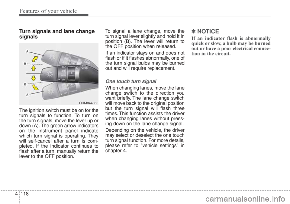
Turn signals and lane change
signals
The ignition switch must be on for the
turn signals to function. To turn on
the turn signals, move the lever up or
down (A). The green arrow indicators
on the instrument panel indicate
which turn signal is operating. They
will self-cancel after a turn is com-
pleted. If the indicator continues to
flash after a turn, manually return the
lever to the OFF position. To signal a lane change, move the
turn signal lever slightly and hold it in
position (B). The lever will return to
the OFF position when released.
If an indicator stays on and does not
flash or if it flashes abnormally, one of
the turn signal bulbs may be burned
out and will require replacement.
One touch turn signal
When changing lanes, move the lane
change switch to the direction you
want briefly. The lane change switch
will move back to the original position
but the turn signal will flash three
times. This function assists the driver
when changing lanes without press-
ing down on the lane change signal.
Depending on the vehicle, the driver
may select or deselect the one touch
turn signal function. For more details,
please refer to "vehicle settings" in
chapter 4.
✽ ✽
NOTICE
If an indicator flash is abnormally
quick or slow, a bulb may be burned
out or have a poor electrical connec-
tion in the circuit.
OUM044060
Page 243 of 576
Features of your vehicle
158
4
This indicator illuminates
when the auto defogging
system senses the mois-
ture on the inside of the
windshield and operates.
If more moisture is in the vehicle,
higher steps operate as follow. For
example if auto defogging does not
defog inside the windshield at step 1
Outside air position, it tries to defog
again at step 2 Blowing air toward
the windshield.
Step 1 : Outside air position
Step 2 :Blowing air toward the wind-
shield
Step 3 : Increasing air flow toward the windshield
Step 4 : Operating the air conditioning
Step 5 : M aximizing the air condi-
tioning To cancel or reset the Auto Defogging
System
Press the front windshield defroster
button for 3 seconds when the igni-
tion switch is in the ON position.
When the Auto Defogging System is
canceled, ADS OFF symbol will blink
3 times and the ADS OFF will be dis-
played on the climate control infor-
mation screen.
When the Auto Defogging System is
reset, ADS OFF symbol will blink 6
times without a signal.
✽ ✽
NOTICE
If the A/C off or recirculated air
position is manually selected while
the auto defogging system is on, the
auto defogging indicator will blink 3
times to give notice that manual
operation is canceled.
Do not remove the sensor cover
located on the upper end of the pas-
senger side windshield glass.
Damage to the system parts could
occur and may not be covered by
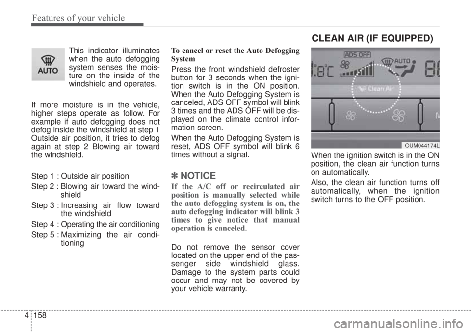
your vehicle warranty. When the ignition switch is in the ON
position, the clean air function turns
on automatically.
Also, the clean air function turns off
automatically, when the ignition
switch turns to the OFF position.
CLEAN AIR (IF EQUIPPED)
OUM044174L
Page 257 of 576
Features of your vehicle
172 4
If you install aftermarket HID head
lamps, your vehicle’s audio and elec-
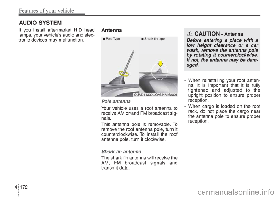
tronic devices may malfunction.Antenna
Pole antenna
Your vehicle uses a roof antenna to
receive AM or/and FM broadcast sig-
nals.
This antenna pole is removable. To
remove the roof antenna pole, turn it
counterclockwise. To install the roof
antenna pole, turn it clockwise.
Shark fin antenna
The shark fin antenna will receive the
AM, FM broadcast signals and
transmit data. When reinstalling your roof anten-
na, it is important that it is fully
tightened and adjusted to the
upright position to ensure proper
reception.
When cargo is loaded on the roof
rack, do not place the cargo near
the antenna pole to ensure proper
reception.
AUDIO SYSTEM
CAUTION- Antenna
Before entering a place with a
low height clearance or a car
wash, remove the antenna pole
by rotating it counterclockwise.
If not, the antenna may be dam-
aged.
OUM044339L/OANNMM2901
■Pole Type■Shark fin type