ignition KIA VENGA 2011 Owners Manual
[x] Cancel search | Manufacturer: KIA, Model Year: 2011, Model line: VENGA, Model: KIA VENGA 2011Pages: 761, PDF Size: 34.65 MB
Page 615 of 761
What to do in an emergency
4
6
EMERGENCY STARTING
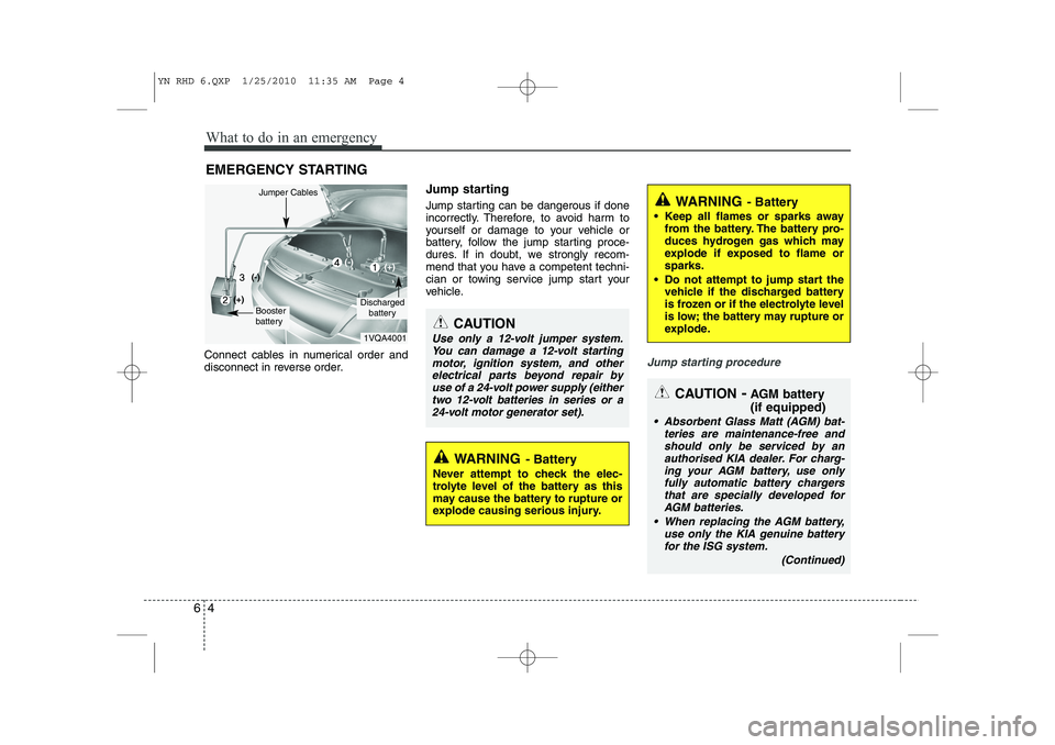
Connect cables in numerical order and
disconnect in reverse order. Jump starting
Jump starting can be dangerous if done
incorrectly. Therefore, to avoid harm to
yourself or damage to your vehicle or
battery, follow the jump starting proce-
dures. If in doubt, we strongly recom-
mend that you have a competent techni-
cian or towing service jump start your
vehicle.
Jump starting procedure
CAUTION
Use only a 12-volt jumper system.
You can damage a 12-volt starting
motor, ignition system, and otherelectrical parts beyond repair by use of a 24-volt power supply (eithertwo 12-volt batteries in series or a
24-volt motor generator set).
WARNING - Battery
• Keep all flames or sparks away from the battery. The battery pro-
duces hydrogen gas which may
explode if exposed to flame orsparks.
Do not attempt to jump start the vehicle if the discharged battery
is frozen or if the electrolyte level
is low; the battery may rupture or
explode.
WARNING - Battery
Never attempt to check the elec-
trolyte level of the battery as this
may cause the battery to rupture or
explode causing serious injury.
1VQA4001
Discharged battery
Jumper Cables
Booster
battery
(-)
(+)
(+)(-)
CAUTION -AGM battery (if equipped)
Absorbent Glass Matt (AGM) bat-
teries are maintenance-free and
should only be serviced by anauthorised KIA dealer. For charg-ing your AGM battery, use only fully automatic battery chargers
that are specially developed forAGM batteries.
When replacing the AGM battery, use only the KIA genuine batteryfor the ISG system.
(Continued)
YN RHD 6.QXP 1/25/2010 11:35 AM Page 4
Page 616 of 761
65
What to do in an emergency
1. Make sure the booster battery is 12-volt and that its negative terminal is
grounded.
2. If the booster battery is in another vehicle, do not allow the vehicles comein contact.
3. Turn off all unnecessary electrical loads.
4. Connect the jumper cables in the exact sequence shown in the illustration.First connect one end of a jumper
cable to the positive terminal of the
discharged battery (1), then connect
the other end to the positive terminal
on the booster battery (2). 5. Proceed to connect one end of the
other jumper cable to the negative ter-
minal of the booster battery (3), then
the other end to a solid, stationary,
metallic point (for example, the engine
lifting bracket) away from the battery
(4). Do not connect it to or near any
part that moves when the engine is
cranked.
Do not allow the jumper cables to con-
tact anything except the correct battery
terminals or the correct ground. Do not
lean over the battery when making
connections.
6. Start the engine of the vehicle with the booster battery and let it run at 2,000
rpm, then start the engine of the vehi-
cle with the discharged battery.
If the cause of your battery discharging is
not apparent, you should have your vehi-cle checked by an authorised KIA dealer.
Push-starting
Your manual transaxle-equipped vehicle
should not be push-started because itmight damage the emission control sys-tem.
Vehicles equipped with automatic
transaxle cannot be push-started.
Follow the directions in this section for
jump-starting.
WARNING
Never tow a vehicle to start it
because the sudden surge forward
when the engine starts could cause
a collision with the tow vehicle.
CAUTION - Battery cables
Do not connect the jumper cable
from the negative terminal of the booster battery to the negative ter-minal of the discharged battery. This can cause the discharged bat-
tery to overheat and crack, releas- ing battery acid.
(Continued)
If the AGM battery is reconnected or replaced, ISG function will notoperate immediately.
If you want to use the ISG func-tion, the battery sensor needs to be calibrated for approximately 4hours with the ignition off.
YN RHD 6.QXP 1/25/2010 11:35 AM Page 5
Page 628 of 761
617
What to do in an emergency
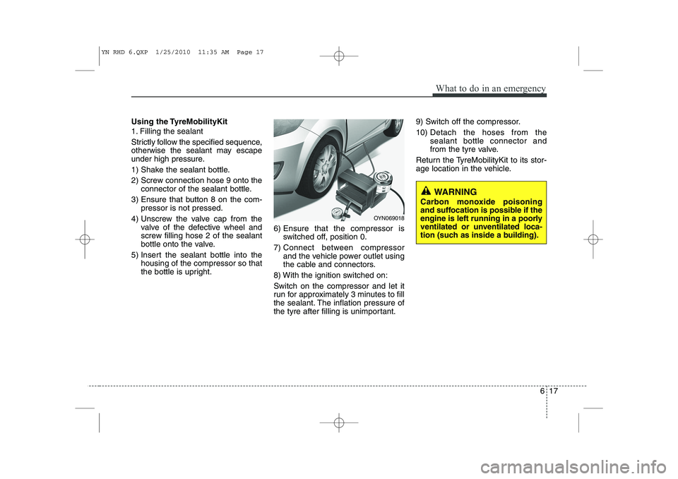
Using the TyreMobilityKit
1. Filling the sealant
Strictly follow the specified sequence,
otherwise the sealant may escape
under high pressure.
1) Shake the sealant bottle.
2) Screw connection hose 9 onto theconnector of the sealant bottle.
3) Ensure that button 8 on the com- pressor is not pressed.
4) Unscrew the valve cap from the valve of the defective wheel and
screw filling hose 2 of the sealant
bottle onto the valve.
5) Insert the sealant bottle into the housing of the compressor so that
the bottle is upright. 6) Ensure that the compressor is
switched off, position 0.
7) Connect between compressor and the vehicle power outlet using
the cable and connectors.
8) With the ignition switched on: Switch on the compressor and let it
run for approximately 3 minutes to fill
the sealant. The inflation pressure of
the tyre after filling is unimportant. 9) Switch off the compressor. 10)
Detach the hoses from the sealant bottle connector and
from the tyre valve.
Return the TyreMobilityKit to its stor-
age location in the vehicle.
WARNING
Carbon monoxide poisoning
and suffocation is possible if the
engine is left running in a poorly
ventilated or unventilated loca-
tion (such as inside a building).
OYN069018
YN RHD 6.QXP 1/25/2010 11:35 AM Page 17
Page 632 of 761
621
What to do in an emergency
✽✽NOTICE
If the TPMS, Low Tyre Pressure and Position indicators do not illuminate
for 3 seconds when the ignitionswitch is turned to the ON position
or engine is running, or if they
remain illuminated after coming on
for approximately 3 seconds, take
your car to your nearest authorised
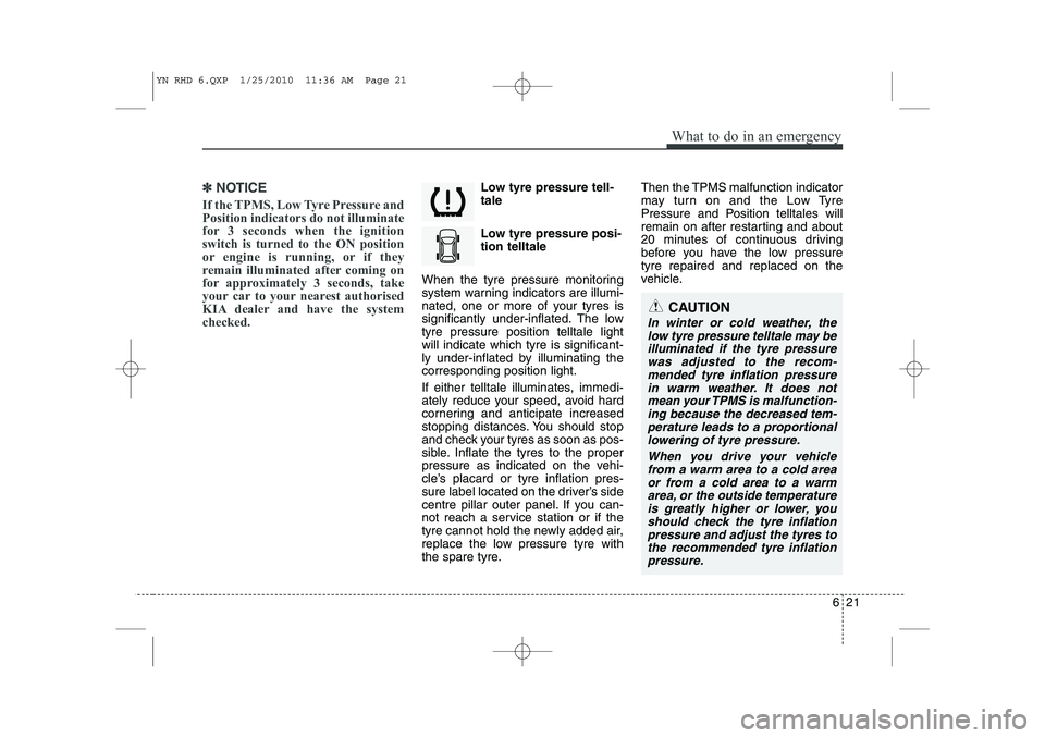
KIA dealer and have the systemchecked.Low tyre pressure tell- tale
Low tyre pressure posi- tion telltale
When the tyre pressure monitoring
system warning indicators are illumi-
nated, one or more of your tyres is
significantly under-inflated. The lowtyre pressure position telltale lightwill indicate which tyre is significant-
ly under-inflated by illuminating thecorresponding position light.
If either telltale illuminates, immedi-
ately reduce your speed, avoid hard
cornering and anticipate increased
stopping distances. You should stop
and check your tyres as soon as pos-
sible. Inflate the tyres to the proper
pressure as indicated on the vehi-
cle’s placard or tyre inflation pres-
sure label located on the driver’s side
centre pillar outer panel. If you can-
not reach a service station or if the
tyre cannot hold the newly added air,
replace the low pressure tyre with
the spare tyre. Then the TPMS malfunction indicator
may turn on and the Low Tyre
Pressure and Position telltales will
remain on after restarting and about
20 minutes of continuous driving
before you have the low pressuretyre repaired and replaced on the
vehicle.
CAUTION
In winter or cold weather, the
low tyre pressure telltale may beilluminated if the tyre pressurewas adjusted to the recom- mended tyre inflation pressurein warm weather. It does notmean your TPMS is malfunction- ing because the decreased tem-perature leads to a proportionallowering of tyre pressure.
When you drive your vehiclefrom a warm area to a cold area or from a cold area to a warmarea, or the outside temperatureis greatly higher or lower, you should check the tyre inflationpressure and adjust the tyres tothe recommended tyre inflation pressure.
YN RHD 6.QXP 1/25/2010 11:36 AM Page 21
Page 637 of 761
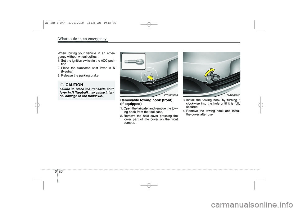
When towing your vehicle in an emer- gency without wheel dollies :
1. Set the ignition switch in the ACC posi-tion.
2. Place the transaxle shift lever in N (Neutral).
3. Release the parking brake.
Removable towing hook (front) (if equipped)
1. Open the tailgate, and remove the tow-ing hook from the tool case.
2. Remove the hole cover pressing the lower part of the cover on the front
bumper. 3. Install the towing hook by turning it
clockwise into the hole until it is fullysecured.
4. Remove the towing hook and install the cover after use.
CAUTION
Failure to place the transaxle shift
lever in N (Neutral) may cause inter-nal damage to the transaxle.
OYN069014OYN069015
626
What to do in an emergency
YN RHD 6.QXP 1/25/2010 11:36 AM Page 26
Page 639 of 761
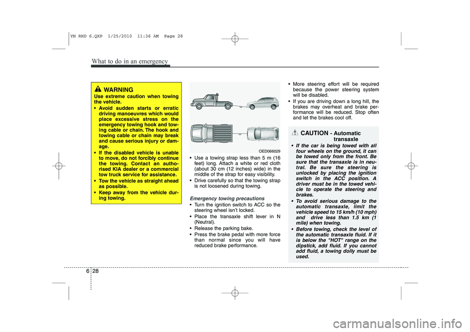
Use a towing strap less than 5 m (16feet) long. Attach a white or red cloth (about 30 cm (12 inches) wide) in the
middle of the strap for easy visibility.
Drive carefully so that the towing strap is not loosened during towing.
Emergency towing precautions
Turn the ignition switch to ACC so thesteering wheel isn’t locked.
Place the transaxle shift lever in N (Neutral).
Release the parking bake.
Press the brake pedal with more force than normal since you will have
reduced brake performance. More steering effort will be required
because the power steering system
will be disabled.
If you are driving down a long hill, the brakes may overheat and brake per-
formance will be reduced. Stop often
and let the brakes cool off.
WARNING
Use extreme caution when towing
the vehicle.
Avoid sudden starts or erratic driving manoeuvres which would
place excessive stress on the
emergency towing hook and tow-
ing cable or chain. The hook and
towing cable or chain may break
and cause serious injury or dam-
age.
If the disabled vehicle is unable to move, do not forcibly continue
the towing. Contact an autho-
rised KIA dealer or a commercial
tow truck service for assistance.
Tow the vehicle as straight ahead as possible.
Keep away from the vehicle dur- ing towing.
CAUTION - Automatic
transaxle
If the car is being towed with all four wheels on the ground, it can
be towed only from the front. Besure that the transaxle is in neu- tral. Be sure the steering isunlocked by placing the ignition
switch in the ACC position. Adriver must be in the towed vehi-cle to operate the steering and brakes.
To avoid serious damage to the automatic transaxle, limit thevehicle speed to 15 km/h (10 mph)and drive less than 1.5 km (1
mile) when towing.
Before towing, check the level of the automatic transaxle fluid. If itis below the "HOT" range on thedipstick, add fluid. If you cannot
add fluid, a towing dolly must beused.OED066029
628
What to do in an emergency
YN RHD 6.QXP 1/25/2010 11:36 AM Page 28
Page 672 of 761
Maintenance
32
7
FUEL FILTER (FOR DIESEL)
Draining water from the fuel filter
The fuel filter for diesel engine plays an
important role of separating water from
fuel and accumulating the water in itsbottom.
If water accumulates in the fuel filter, the
warning light comes on when the ignition
switch is in the ON position. If this warning light illuminates,
take your car to an authorised
KIA dealer and have drain the
water and checked the sys-tem. Extracting air from the fuel filter (Diesel engine)
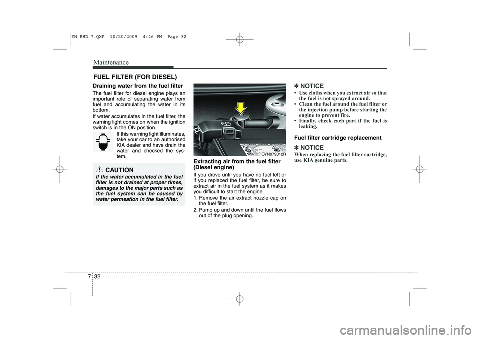
If you drove until you have no fuel left or
if you replaced the fuel filter, be sure to
extract air in the fuel system as it makes
you difficult to start the engine.
1. Remove the air extract nozzle cap on
the fuel filter.
2. Pump up and down until the fuel flows out of the plug opening.
✽✽ NOTICE
Page 678 of 761
Maintenance
38
7
Battery recharging
Your vehicle has a maintenance-free,
calcium-based battery.
If the battery becomes discharged in a
short time (because, for example, the
headlights or interior lights were left on
whilst the vehicle was not in use),
recharge it by slow charging (trickle)
for 10 hours.
If the battery gradually discharges because of high electric load whilst the
vehicle is being used, recharge it at 20-
30A for two hours.(Continued)
When lifting a plastic-cased bat-tery, excessive pressure on the
case may cause battery acid to
leak, resulting in personal injury.
Lift with a battery carrier or with
your hands on opposite corners.
Never attempt to recharge the battery when the battery cablesare connected.
The electrical ignition system works with high voltage. Never
touch these components with theengine running or the ignition
switched on.
Failure to follow the above warn-
ings can result in serious bodily
injury or death.CAUTION -AGM battery (if equipped)
Absorbent Glass Matt (AGM) bat-
teries are maintenance-free and
should only be serviced by an authorised KIA dealer. For charg-ing your AGM battery, use onlyfully automatic battery chargers
that are specially developed forAGM batteries.
When replacing the AGM battery, use only the KIA genuine battery
for the ISG system.
If the AGM battery is reconnected or replaced, ISG function will notoperate immediately.
If you want to use the ISG func-tion, the battery sensor needs to be calibrated for approximately 4hours with the ignition off.
YN RHD 7.QXP 1/25/2010 11:45 AM Page 38
Page 691 of 761
751
Maintenance
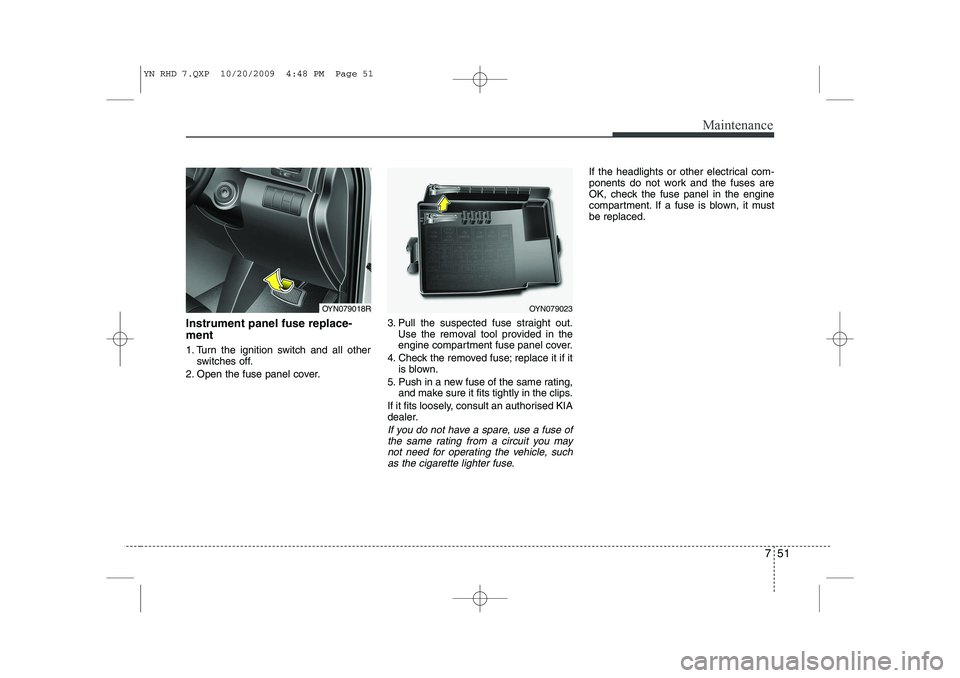
Instrument panel fuse replace- ment
1. Turn the ignition switch and all otherswitches off.
2. Open the fuse panel cover. 3. Pull the suspected fuse straight out.
Use the removal tool provided in the
engine compartment fuse panel cover.
4. Check the removed fuse; replace it if it is blown.
5. Push in a new fuse of the same rating, and make sure it fits tightly in the clips.
If it fits loosely, consult an authorised KIA
dealer.
If you do not have a spare, use a fuse of the same rating from a circuit you may
not need for operating the vehicle, such as the cigarette lighter fuse.
If the headlights or other electrical com-
ponents do not work and the fuses are
OK, check the fuse panel in the engine
compartment. If a fuse is blown, it mustbe replaced.
OYN079023OYN079018R
YN RHD 7.QXP 10/20/2009 4:48 PM Page 51
Page 695 of 761
755
Maintenance
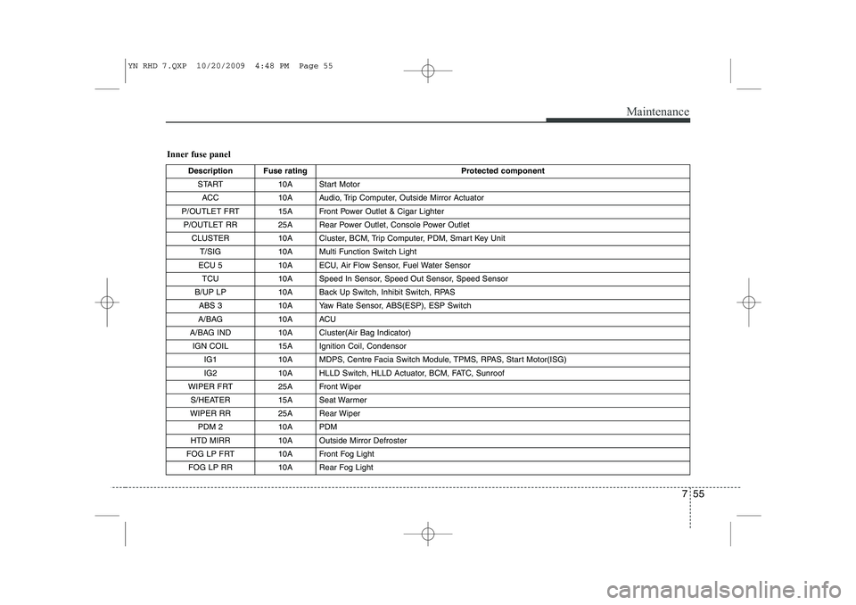
Inner fuse panelDescription Fuse rating Protected component
START 10A Start Motor
ACC 10A Audio, Trip Computer, Outside Mirror Actuator
P/OUTLET FRT 15A Front Power Outlet & Cigar Lighter
P/OUTLET RR 25A Rear Power Outlet, Console Power Outlet CLUSTER 10A Cluster, BCM, Trip Computer, PDM, Smart Key Unit T/SIG 10A Multi Function Switch Light
ECU 5 10A ECU, Air Flow Sensor, Fuel Water Sensor TCU 10A Speed In Sensor, Speed Out Sensor, Speed Sensor
B/UP LP 10A Back Up Switch, Inhibit Switch, RPAS
ABS 3 10A Yaw Rate Sensor, ABS(ESP), ESP Switch
A/BAG 10A ACU
A/BAG IND 10A Cluster(Air Bag Indicator) IGN COIL 15A Ignition Coil, Condensor IG1 10A MDPS, Centre Facia Switch Module, TPMS, RPAS, Start Motor(ISG)
IG2 10A HLLD Switch, HLLD Actuator, BCM, FATC, Sunroof
WIPER FRT 25A Front Wiper S/HEATER 15A Seat Warmer
WIPER RR 25A Rear Wiper PDM 2 10A PDM
HTD MIRR 10A Outside Mirror Defroster
FOG LP FRT10AFront Fog Light
FOG LP RR10ARear Fog Light
YN RHD 7.QXP 10/20/2009 4:48 PM Page 55