battery KIA VENGA 2015 Owners Manual
[x] Cancel search | Manufacturer: KIA, Model Year: 2015, Model line: VENGA, Model: KIA VENGA 2015Pages: 480, PDF Size: 23.15 MB
Page 5 of 480
5
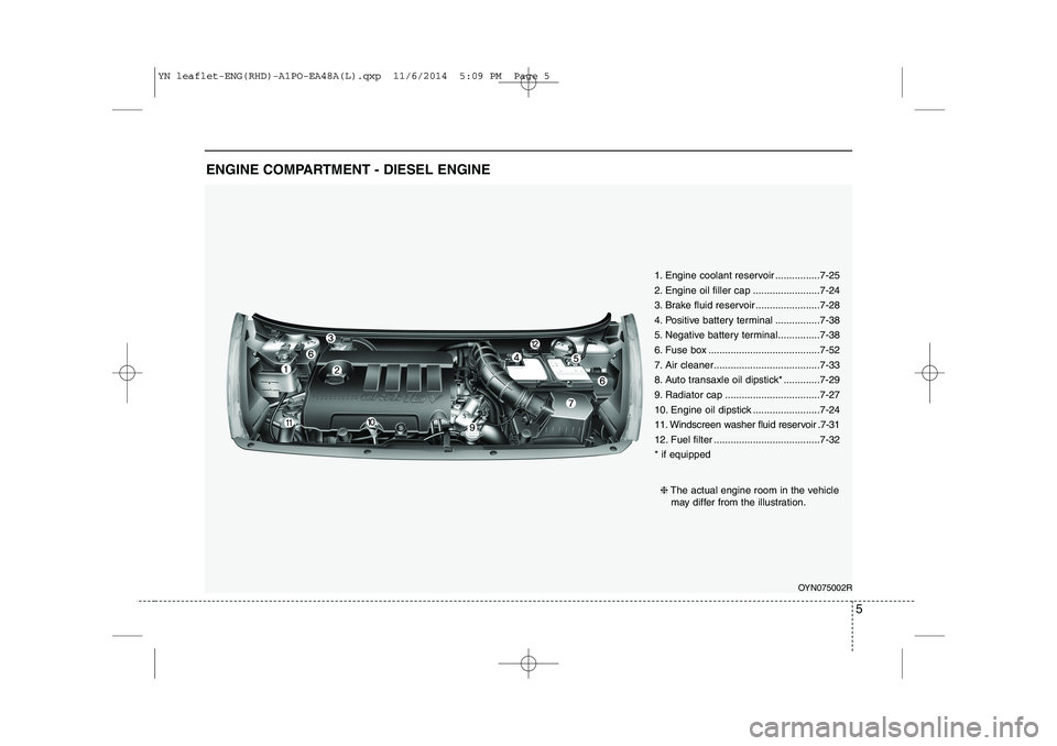
ENGINE COMPARTMENT - DIESEL ENGINE
OYN075002R
❈
The actual engine room in the vehicle
may differ from the illustration.
1. Engine coolant reservoir ................7-25
2. Engine oil filler cap ........................7-24
3. Brake fluid reservoir .......................7-28
4. Positive battery terminal ................7-38
5. Negative battery terminal...............7-38
6. Fuse box ........................................7-52
7. Air cleaner......................................7-33
8. Auto transaxle oil dipstick* .............7-29
9. Radiator cap ..................................7-27
10. Engine oil dipstick ........................7-24
11. Windscreen washer fluid reservoir .7-31
12. Fuel filter ......................................7-32 * if equipped
YN leaflet-ENG(RHD)-A1PO-EA48A(L).qxp 11/6/2014 5:09 PM Page 5
Page 8 of 480
❖❖Please see this page instead of page 4-5 in owner's manual.
8
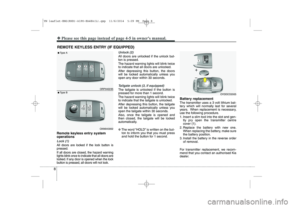
Remote keyless entry system operations
Lock (1)
All doors are locked if the lock button is pressed.
If all doors are closed, the hazard warning
lights blink once to indicate that all doors are
locked. If any door is opened when the lock
button is pressed, all doors will not lock.
Unlock (2)
All doors are unlocked if the unlock but- ton is pressed.
The hazard warning lights will blink twice
to indicate that all doors are unlocked.
After depressing this button, the doors
will be locked automatically unless you
open any door within 30 seconds.
Tailgate unlock (3, if equipped)
The tailgate is unlocked if the button is
pressed for more than 1 second.
The hazard warning lights will blink twice
to indicate that the tailgate is unlocked.
After depressing this button, the tailgate
will be locked automatically unless you
open the tailgate within 30 seconds.
Also, once the tailgate is opened and
then closed, the tailgate will be locked
automatically. ❈The word “HOLD” is written on the but-
ton to inform you that you must press
and hold the button for 1 second. Battery replacement
The transmitter uses a 3 volt lithium bat-
tery which will normally last for several
years. When replacement is necessary,
use the following procedure.
1. Insert a slim tool into the slot and gen-
tly pry open the transmitter centre
cover (1).
2. Replace the battery with new one. When replacing the battery, make sure
the battery position.
3. Install the battery in the reverse order of removal.
For transmitter replacement, we recom-
mend that you contact an authorised Kia
dealer.
REMOTE KEYLESS ENTRY (IF EQUIPPED) ORP042235
OXM043002
■
Type A
■ Type B
OYDDCO2005
YN leaflet-ENG(RHD)-A1PO-EA48A(L).qxp 11/6/2014 5:09 PM Page 8
Page 27 of 480
27
Press the SET button less than 1 second to select the mode and set the data usingthe UP(▲) and DOWN( ▼) button whilst
the selected setting mode blinks.
To cancel the SET UP mode, do one of
the following :
- Press the SET button less than 1 sec- ond in set-up temperature unit change mode
- Press the SET button more than 1 sec- ond in any set-up mode
- After 15 seconds without any key press
- Ignition is ON or OFF in set-up mode
- Battery is disconnected * if equipped Cigarette lighter (if equipped)
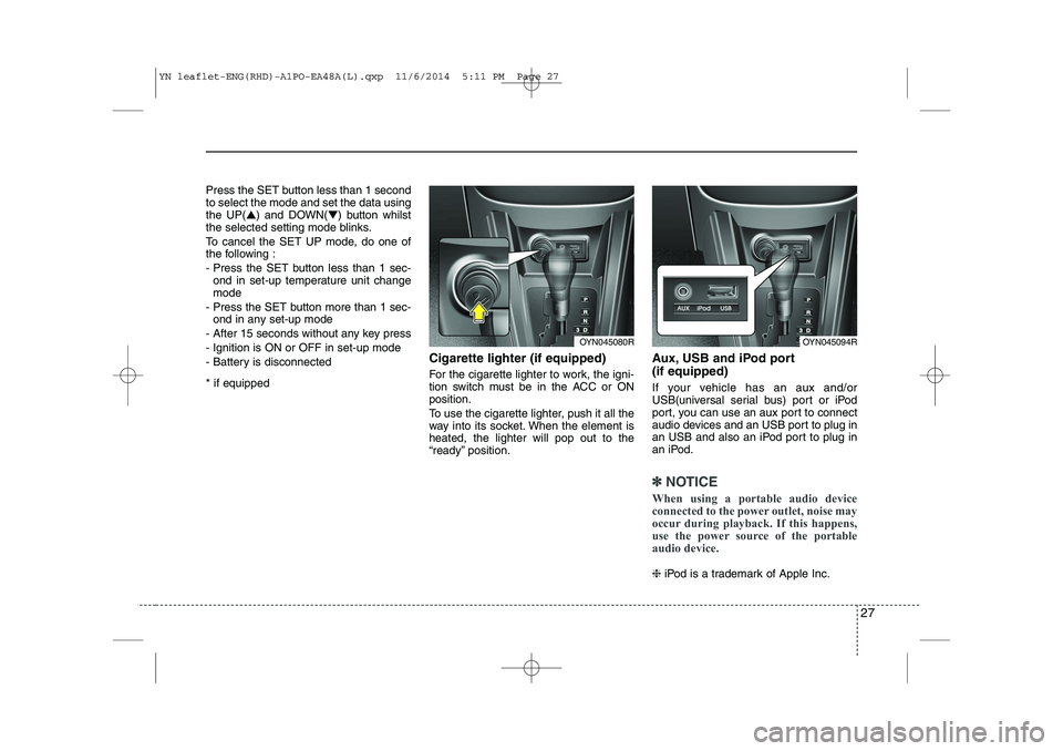
For the cigarette lighter to work, the igni-
tion switch must be in the ACC or ONposition.
To use the cigarette lighter, push it all the
way into its socket. When the element isheated, the lighter will pop out to the
“ready” position.Aux, USB and iPod port (if equipped)
If your vehicle has an aux and/or
USB(universal serial bus) port or iPod
port, you can use an aux port to connect
audio devices and an USB port to plug in
an USB and also an iPod port to plug in
an iPod.
✽✽
NOTICE
When using a portable audio device
connected to the power outlet, noise may
occur during playback. If this happens,
use the power source of the portable
audio device.
❈ iPod is a trademark of Apple Inc.
OYN045080ROYN045094R
YN leaflet-ENG(RHD)-A1PO-EA48A(L).qxp 11/6/2014 5:11 PM Page 27
Page 28 of 480
28
❖❖Please see this page instead of page 5-14 in owner's manual.
ISG(Idle Stop and Go) system
deactivation
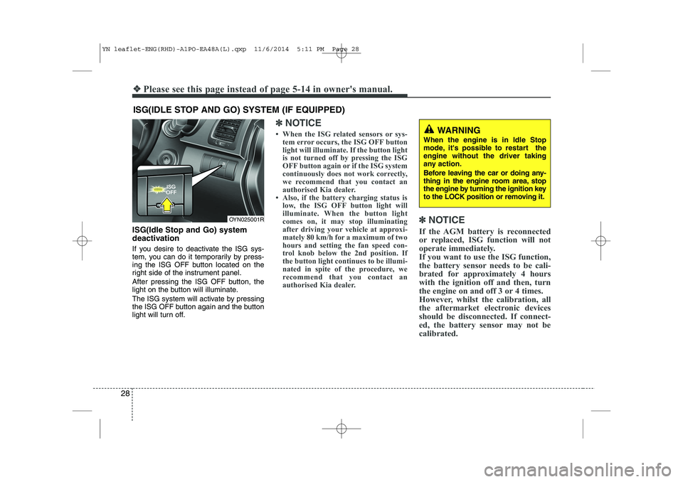
If you desire to deactivate the ISG sys-
tem, you can do it temporarily by press-
ing the ISG OFF button located on the
right side of the instrument panel.
After pressing the ISG OFF button, the
light on the button will illuminate.
The ISG system will activate by pressing
the ISG OFF button again and the button
light will turn off.
✽✽NOTICE
When the ISG related sensors or sys- tem error occurs, the ISG OFF button
light will illuminate. If the button light
is not turned off by pressing the ISG
OFF button again or if the ISG system
continuously does not work correctly,
we recommend that you contact an
authorised Kia dealer.
Also, if the battery charging status is low, the ISG OFF button light will
illuminate. When the button light
comes on, it may stop illuminating
after driving your vehicle at approxi-
mately 80 km/h for a maximum of two
hours and setting the fan speed con-
trol knob below the 2nd position. If
the button light continues to be illumi-
nated in spite of the procedure, we
recommend that you contact an
authorised Kia dealer. ✽
✽
NOTICE
If the AGM battery is reconnected
or replaced, ISG function will not
operate immediately.
If you want to use the ISG function,
the battery sensor needs to be cali-
brated for approximately 4 hours
with the ignition off and then, turn
the engine on and off 3 or 4 times.
However, whilst the calibration, all
the aftermarket electronic devices
should be disconnected. If connect-
ed, the battery sensor may not be
calibrated.
ISG(IDLE STOP AND GO) SYSTEM (IF EQUIPPED)
OYN025001R
WARNING
When the engine is in Idle Stop
mode, it's possible to restart theengine without the driver taking
any action.
Before leaving the car or doing any-
thing in the engine room area, stop
the engine by turning the ignition key
to the LOCK position or removing it.
YN leaflet-ENG(RHD)-A1PO-EA48A(L).qxp 11/6/2014 5:11 PM Page 28
Page 38 of 480
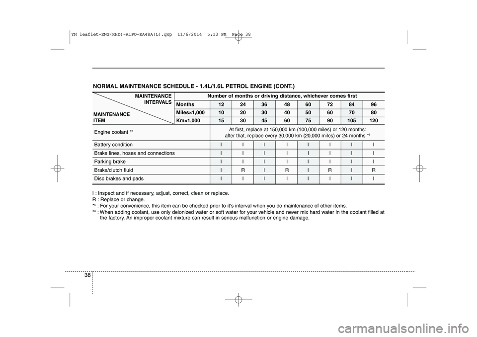
38
Number of months or driving distance, whichever comes first
Months 12 24 36 48 60 72 84 96 Miles×1,000
10 20 30 40 50 60 70 80
Km×1,00015 30 45 60 75 90 105 120
Engine coolant * 8
Battery condition I I I I I I I I
Brake lines, hoses and connections I I I I I I I I
Parking brake I I I I I I I I
Brake/clutch fluid
IRI RIRIR
Disc brakes and pads I I I I I I I I
I : Inspect and if necessary, adjust, correct, clean or replace.
R : Replace or change.* 5
: For your convenience, this item can be checked prior to it's interval when you do maintenance of other items.
* 8
: When adding coolant, use only deionized water or soft water for your vehicle and never mix hard water in the coolant filled at
the factory. An improper coolant mixture can result in serious malfunction or engine damage.
At first, replace at 150,000 km (100,000 miles) or 120 months:
after that, replace every
30,000 km (20,000 miles)or 24 months * 5
MAINTENANCE
INTERVALS
MAINTENANCE ITEM
NORMAL MAINTENANCE SCHEDULE - 1.4L/1.6L PETROL ENGINE (CONT.)
YN leaflet-ENG(RHD)-A1PO-EA48A(L).qxp 11/6/2014 5:13 PM Page 38
Page 44 of 480
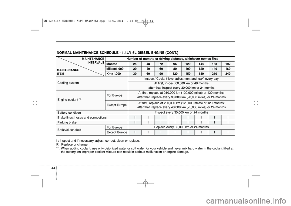
44
NORMAL MAINTENANCE SCHEDULE - 1.4L/1.6L DIESEL ENGINE (CONT.)
I : Inspect and if necessary, adjust, correct, clean or replace.
R : Replace or change.*7
: When adding coolant, use only deionized water or soft water for your vehicle and never mix hard water in the coolant filled at
the factory. An improper coolant mixture can result in serious malfunction or engine damage.
MAINTENANCE
INTERVALS
MAINTENANCE ITEM
At first, replace at 210,000 km (120,000 miles) or 120 months:
after that, replace every 30,000 km (20,000 miles) or 24 months
Inspect every 30,000 km or 24 months
Number of months or driving distance, whichever comes first
Months24 48 72 96 120 144 168 192
Miles×1,000 20 40 60 80 100 120 140 160
Km×1,000 30 60 90 120 150 180 210 240
Cooling system
For Europe
Engine coolant * 7
Except Europe
Battery condition
Brake lines, hoses and connections I I I I I I I I
Parking brake
I I I I I I I I
Brake/clutch fluid For Europe
Except Europe I I I I I I I IInspect “Coolant level adjustment and leak” every day
At first, inspect 60,000 km or 48 months
after that, inspect every 30,000 km or 24 months
Replaceevery 30,000 km or 24 months
At first, replace at 200,000 km (120,000 miles) or 120 months:
after that, replace every 40,000 km (25,000 miles) or 24 months
YN leaflet-ENG(RHD)-A1PO-EA48A(L).qxp 11/6/2014 5:13 PM Page 44
Page 48 of 480
48
❖❖Please see these pages instead of page 7-52 ~ 7-62 in owner's manual.
FUSES
A vehicle’s electrical system is protected
from electrical overload damage by
fuses. This vehicle has 2 (or 3) fuse panels, one
located in the driver’s side panel bolster,
the other in the engine compartment near
the battery.
If any of your vehicle’s lights, accessories,
or controls do not work, check the appro-
priate circuit fuse. If the fuse is discon-
nected, every electrical system protected
by the fuse will not operate. Therefore,
you must change the fuse.
If the electrical system does not work, first
check the driver’s side fuse panel.
Always replace a blown fuse with one of
the same rating.
Before replacing a blown fuse, disconnect
the negative battery cable.
If the replacement fuse blows, this indi-
cates an electrical problem. Avoid using
the system involved and we recommend
that you consult an authorised Kia dealer.
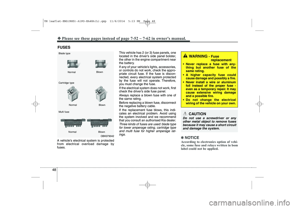
Three kinds of fuses are used: blade type
for lower amperage rating, cartridge type
and multi fuse for higher amperage rat- ings.
✽✽ NOTICE
According to electronics option of vehi-
cle, some fuse and relays written in bom
label could not be applied.OBK079042
Normal
Normal
Cartridge type Multi fuse Blown
Blown
Normal Blown
WARNING - Fuse
replacement
Never replace a fuse with any- thing but another fuse of the same rating.
A higher capacity fuse could cause damage and possibly a fire.
Never install a wire or aluminum foil instead of the proper fuse -
even as a temporary repair. It may
cause extensive wiring damage
and a possible fire.
Do not change the electrical
wiring of the vehicle on your own.
CAUTION
Do not use a screwdriver or any
other metal object to remove fuses
because it may cause a short circuitand damage the system.
Blade type
YN leaflet-ENG(RHD)-A1PO-EA48A(L).qxp 11/6/2014 5:13 PM Page 48
Page 50 of 480
50
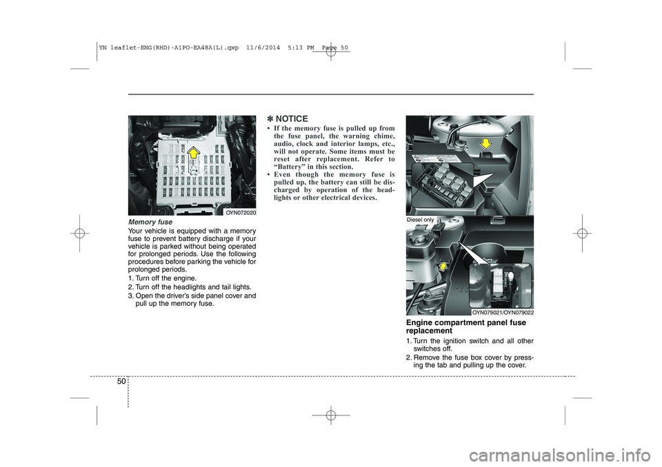
Memory fuse
Your vehicle is equipped with a memory
fuse to prevent battery discharge if your
vehicle is parked without being operated
for prolonged periods. Use the following
procedures before parking the vehicle for
prolonged periods.
1. Turn off the engine.
2. Turn off the headlights and tail lights.
3. Open the driver’s side panel cover andpull up the memory fuse.
✽✽ NOTICE
If the memory fuse is pulled up from the fuse panel, the warning chime,
audio, clock and interior lamps, etc.,
will not operate. Some items must be
reset after replacement. Refer to
“Battery” in this section.
Even though the memory fuse is
pulled up, the battery can still be dis-
charged by operation of the head-
lights or other electrical devices.
Engine compartment panel fuse replacement
1. Turn the ignition switch and all other switches off.
2. Remove the fuse box cover by press- ing the tab and pulling up the cover.
OYN072020
OYN079021/OYN079022
Diesel only
YN leaflet-ENG(RHD)-A1PO-EA48A(L).qxp 11/6/2014 5:13 PM Page 50
Page 51 of 480
51
3. Check the removed fuse; replace it if itis blown. To remove or insert the fuse, use the fuse puller in the engine com-
partment fuse panel.
4. Push in a new fuse of the same rating, and make sure it fits tightly in the clips.
If it fits loosely, we recommend that
you consult an authorised Kia dealer.
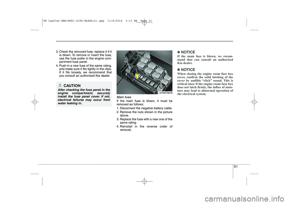
Main fuse
If the main fuse is blown, it must be
removed as follows:
1. Disconnect the negative battery cable.
2. Remove the nuts shown in the pictureabove.
3. Replace the fuse with a new one of the same rating.
4. Reinstall in the reverse order of removal.
✽✽ NOTICE
If the main fuse is blown, we recom-
mend that you consult an authorised
Kia dealer.
✽
✽ NOTICE
When closing the engine room fuse box
cover, confirm the solid latching of the
cover by audible “click” sound. This is
critical since if the engine room fuse box
does not latch firmly, the influx of mois-
ture may lead to abnormal operation of
the electrical system.
CAUTION
After checking the fuse panel in the engine compartment, securely
install the fuse panel cover. If not,electrical failures may occur from water leaking in.OYN079019
YN leaflet-ENG(RHD)-A1PO-EA48A(L).qxp 11/6/2014 5:13 PM Page 51
Page 57 of 480
57
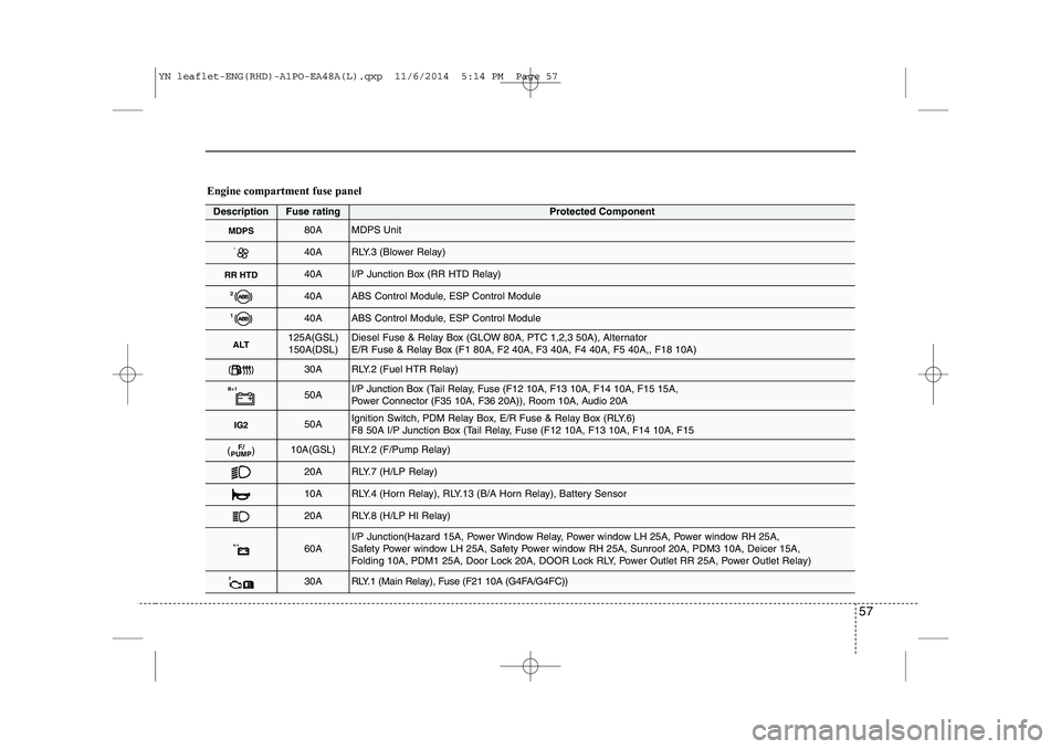
Engine compartment fuse panel
DescriptionFuse ratingProtected Component
MDPS80AMDPS Unit
140ARLY.3 (Blower Relay)
RR HTD40AI/P Junction Box (RR HTD Relay)
240AABS Control Module, ESP Control Module
140AABS Control Module, ESP Control Module
ALT125A(GSL)150A(DSL)Diesel Fuse & Relay Box (GLOW 80A, PTC 1,2,3 50A), Alternator
E/R Fuse & Relay Box (F1 80A, F2 40A, F3 40A, F4 40A, F5 40A,, F18 10A)
30ARLY.2 (Fuel HTR Relay)
B+150AI/P Junction Box (Tail Relay, Fuse (F12 10A, F13 10A, F14 10A, F15 15A,
Power Connector (F35 10A, F36 20A)), Room 10A, Audio 20A
IG250AIgnition Switch, PDM Relay Box, E/R Fuse & Relay Box (RLY.6)
F8 50A I/P Junction Box (Tail Relay, Fuse (F12 10A, F13 10A, F14 10A, F15
F/
PUMP( )10A(GSL)RLY.2 (F/Pump Relay)
20ARLY.7 (H/LP Relay)
10ARLY.4 (Horn Relay), RLY.13 (B/A Horn Relay), Battery Sensor
20ARLY.8 (H/LP HI Relay)
B+260AI/P Junction(Hazard 15A, Power Window Relay, Power window LH 25A, Power window RH 25A,
Safety Power window LH 25A, Safety Power window RH 25A, Sunroof 20A, PDM3 10A, Deicer 15A,
Folding 10A, PDM1 25A, Door Lock 20A, DOOR Lock RLY, Power Outlet RR 25A, Power Outlet Relay)
230ARLY.1 (Main Relay), Fuse (F21 10A (G4FA/G4FC))
YN leaflet-ENG(RHD)-A1PO-EA48A(L).qxp 11/6/2014 5:14 PM Page 57