sensor KIA VENGA 2015 Owners Manual
[x] Cancel search | Manufacturer: KIA, Model Year: 2015, Model line: VENGA, Model: KIA VENGA 2015Pages: 480, PDF Size: 23.15 MB
Page 28 of 480
28
❖❖Please see this page instead of page 5-14 in owner's manual.
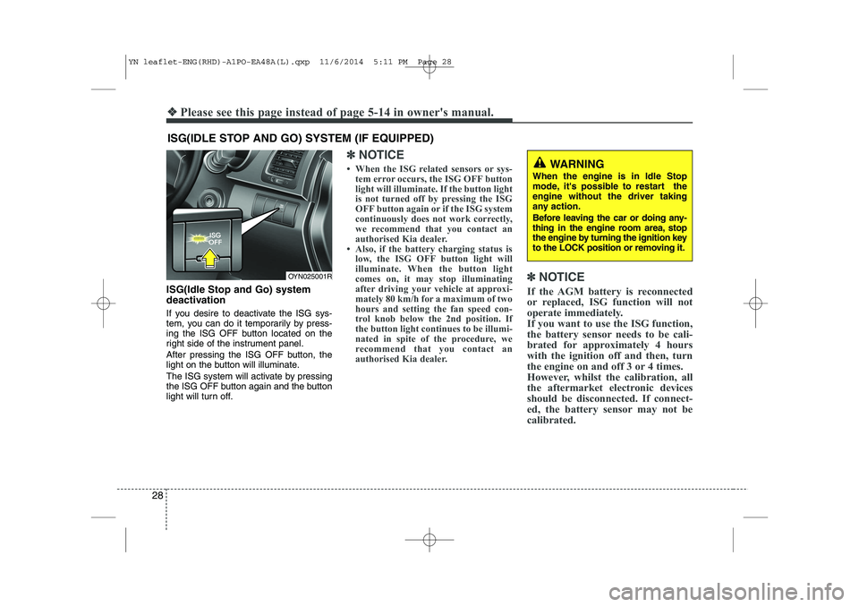
ISG(Idle Stop and Go) system
deactivation
If you desire to deactivate the ISG sys-
tem, you can do it temporarily by press-
ing the ISG OFF button located on the
right side of the instrument panel.
After pressing the ISG OFF button, the
light on the button will illuminate.
The ISG system will activate by pressing
the ISG OFF button again and the button
light will turn off.
✽✽NOTICE
When the ISG related sensors or sys- tem error occurs, the ISG OFF button
light will illuminate. If the button light
is not turned off by pressing the ISG
OFF button again or if the ISG system
continuously does not work correctly,
we recommend that you contact an
authorised Kia dealer.
Also, if the battery charging status is low, the ISG OFF button light will
illuminate. When the button light
comes on, it may stop illuminating
after driving your vehicle at approxi-
mately 80 km/h for a maximum of two
hours and setting the fan speed con-
trol knob below the 2nd position. If
the button light continues to be illumi-
nated in spite of the procedure, we
recommend that you contact an
authorised Kia dealer. ✽
✽
NOTICE
If the AGM battery is reconnected
or replaced, ISG function will not
operate immediately.
If you want to use the ISG function,
the battery sensor needs to be cali-
brated for approximately 4 hours
with the ignition off and then, turn
the engine on and off 3 or 4 times.
However, whilst the calibration, all
the aftermarket electronic devices
should be disconnected. If connect-
ed, the battery sensor may not be
calibrated.
ISG(IDLE STOP AND GO) SYSTEM (IF EQUIPPED)
OYN025001R
WARNING
When the engine is in Idle Stop
mode, it's possible to restart theengine without the driver taking
any action.
Before leaving the car or doing any-
thing in the engine room area, stop
the engine by turning the ignition key
to the LOCK position or removing it.
YN leaflet-ENG(RHD)-A1PO-EA48A(L).qxp 11/6/2014 5:11 PM Page 28
Page 53 of 480
53
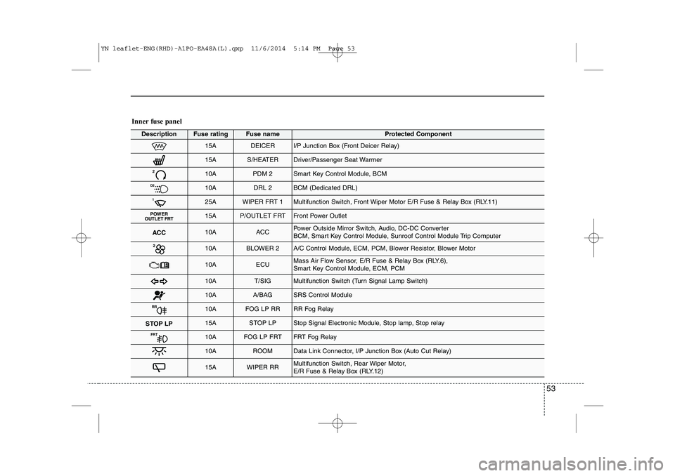
Inner fuse panel
DescriptionFuse ratingFuse nameProtected Component
15ADEICERI/P Junction Box (Front Deicer Relay)
15AS/HEATERDriver/Passenger Seat Warmer
210APDM 2Smart Key Control Module, BCM
D210ADRL 2BCM (Dedicated DRL)
125AWIPER FRT 1Multifunction Switch, Front Wiper Motor E/R Fuse & Relay Box (RLY.11)
POWER
OUTLET FRT15AP/OUTLET FRTFront Power Outlet
ACC10AACCPower Outside Mirror Switch, Audio, DC-DC Converter
BCM, Smart Key Control Module, Sunroof Control Module Trip Computer
210ABLOWER 2A/C Control Module, ECM, PCM, Blower Resistor, Blower Motor
10AECUMass Air Flow Sensor, E/R Fuse & Relay Box (RLY.6),
Smart Key Control Module, ECM, PCM
10AT/SIGMultifunction Switch (Turn Signal Lamp Switch)
10AA/BAGSRS Control Module
RR10AFOG LP RRRR Fog Relay
STOP LP15ASTOP LPStop Signal Electronic Module, Stop lamp, Stop relay
FRT10AFOG LP FRTFRT Fog Relay
10AROOMData Link Connector, I/P Junction Box (Auto Cut Relay)
15AWIPER RRMultifunction Switch, Rear Wiper Motor,
E/R Fuse & Relay Box (RLY.12)
YN leaflet-ENG(RHD)-A1PO-EA48A(L).qxp 11/6/2014 5:14 PM Page 53
Page 54 of 480
54
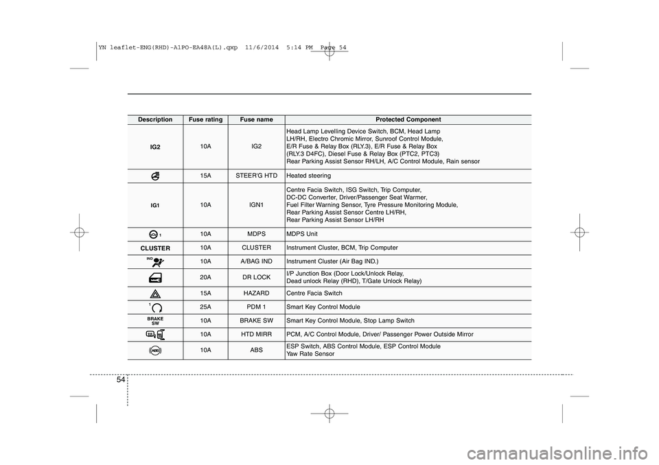
DescriptionFuse ratingFuse nameProtected Component
IG210AIG2
Head Lamp Levelling Device Switch, BCM, Head Lamp
LH/RH, Electro Chromic Mirror, Sunroof Control Module,
E/R Fuse & Relay Box (RLY.3), E/R Fuse & Relay Box
(RLY.3 D4FC), Diesel Fuse & Relay Box (PTC2, PTC3)
Rear Parking Assist Sensor RH/LH, A/C Control Module, Rain sensor
15ASTEER'G HTDHeated steering
IG110AIGN1
Centre Facia Switch, ISG Switch, Trip Computer,
DC-DC Converter, Driver/Passenger Seat Warmer,
Fuel Filter Warning Sensor, Tyre Pressure Monitoring Module,
Rear Parking Assist Sensor Centre LH/RH,
Rear Parking Assist Sensor LH/RH
110AMDPSMDPS Unit
CLUSTER10ACLUSTERInstrument Cluster, BCM, Trip Computer
IND10AA/BAG INDInstrument Cluster (Air Bag IND.)
20ADR LOCKI/P Junction Box (Door Lock/Unlock Relay,
Dead unlock Relay (RHD), T/Gate Unlock Relay)
15AHAZARDCentre Facia Switch
125APDM 1Smart Key Control Module
BRAKESW10ABRAKE SWSmart Key Control Module, Stop Lamp Switch
10AHTD MIRRPCM, A/C Control Module, Driver/ Passenger Power Outside Mirror
10AABSESP Switch, ABS Control Module, ESP Control Module
Yaw Rate Sensor
YN leaflet-ENG(RHD)-A1PO-EA48A(L).qxp 11/6/2014 5:14 PM Page 54
Page 55 of 480
55
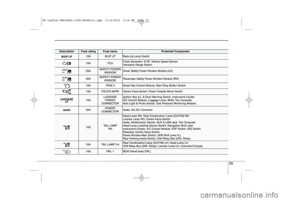
DescriptionFuse ratingFuse nameProtected Component
B/UP LP10AB/UP LPBack-Up Lamp Switch
15ATCUPulse Generator 'A'/'B', Vehicle Speed Sensor
Transaxle Range Switch
SAFETY LH 25ASAFETY POWERWINDOWDriver Safety Power Window Module (LH)
SAFETY RH 25ASAFETY POWERWINDOWPassenger Safety Power Window Module (RH)
310APDM 3Smart Key Control Module, Start Stop Button Switch
10AFOLD'G MIRRCentre Facia Switch, Power Outside Mirror Switch
LUGGAGE LP10ALUGGAGE
POWER
CONNECTORIgnition Key ILL. & Door Warning Switch, Instrument Cluster
A/C Control Module, Luggage Lamp, BCM, Trip Computer
Auto Light & Photo Sensor, Tyre Pressure Monitoring Module
AUDIO20APOWER
CONNECTORAudio, DC-DC Converter
RH10ATAIL LAMP RH
Head Lamp RH, Rear Combination Lamp (OUT/IN) RH
License Lamp RH, Centre Facia Switch
Audio, Multifunction Switch, AUX & USB Jack, Trip Computer
Head Lamp Levelling Device Switch, Navigation Multi Jack
Instrument Cluster, A/C Control Module, ESP Switch, ISG Switch
Rheostat, Centre Facia Switch,
Power Window Main Switch, ATM Shift Lever ILL.
Rear Parking Assist Switch, ICM Relay Box (DRL Relay)
LH10ATAIL LAMP LHRear Combination Lamp (OUT/IN) LH, Head Lamp LH
ICM Relay Box (DRL Relay), License Lamp LH, Instrument Cluster
D110ADRL 1BCM (Head lamp DRL)
YN leaflet-ENG(RHD)-A1PO-EA48A(L).qxp 11/6/2014 5:14 PM Page 55
Page 57 of 480
57
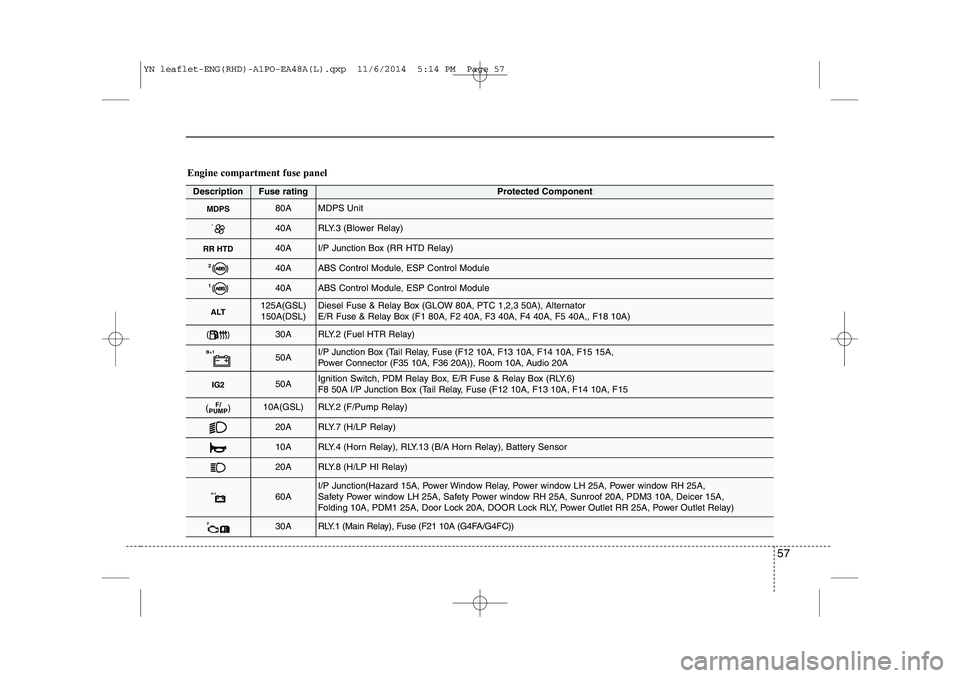
Engine compartment fuse panel
DescriptionFuse ratingProtected Component
MDPS80AMDPS Unit
140ARLY.3 (Blower Relay)
RR HTD40AI/P Junction Box (RR HTD Relay)
240AABS Control Module, ESP Control Module
140AABS Control Module, ESP Control Module
ALT125A(GSL)150A(DSL)Diesel Fuse & Relay Box (GLOW 80A, PTC 1,2,3 50A), Alternator
E/R Fuse & Relay Box (F1 80A, F2 40A, F3 40A, F4 40A, F5 40A,, F18 10A)
30ARLY.2 (Fuel HTR Relay)
B+150AI/P Junction Box (Tail Relay, Fuse (F12 10A, F13 10A, F14 10A, F15 15A,
Power Connector (F35 10A, F36 20A)), Room 10A, Audio 20A
IG250AIgnition Switch, PDM Relay Box, E/R Fuse & Relay Box (RLY.6)
F8 50A I/P Junction Box (Tail Relay, Fuse (F12 10A, F13 10A, F14 10A, F15
F/
PUMP( )10A(GSL)RLY.2 (F/Pump Relay)
20ARLY.7 (H/LP Relay)
10ARLY.4 (Horn Relay), RLY.13 (B/A Horn Relay), Battery Sensor
20ARLY.8 (H/LP HI Relay)
B+260AI/P Junction(Hazard 15A, Power Window Relay, Power window LH 25A, Power window RH 25A,
Safety Power window LH 25A, Safety Power window RH 25A, Sunroof 20A, PDM3 10A, Deicer 15A,
Folding 10A, PDM1 25A, Door Lock 20A, DOOR Lock RLY, Power Outlet RR 25A, Power Outlet Relay)
230ARLY.1 (Main Relay), Fuse (F21 10A (G4FA/G4FC))
YN leaflet-ENG(RHD)-A1PO-EA48A(L).qxp 11/6/2014 5:14 PM Page 57
Page 58 of 480
58
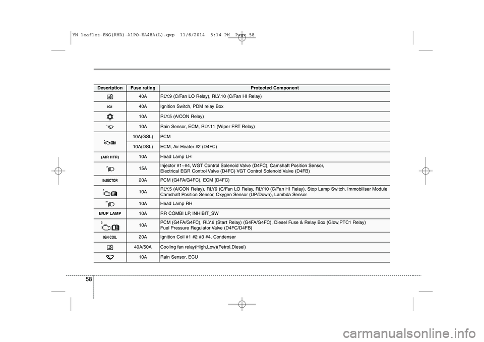
DescriptionFuse ratingProtected Component
40ARLY.9 (C/Fan LO Relay), RLY.10 (C/Fan HI Relay)
IG140AIgnition Switch, PDM relay Box
10ARLY.5 (A/CON Relay)
210ARain Sensor, ECM, RLY.11 (Wiper FRT Relay)
4( )10A(GSL)PCM
10A(DSL)ECM, Air Heater #2 (D4FC)
(AIR HTR)10AHead Lamp LH
LH15AInjector #1~#4, WGT Control Solenoid Valve (D4FC), Camshaft Position Sensor,
Electrical EGR Control Valve (D4FC) VGT Control Solenoid Valve (D4FB)
INJECTOR20APCM (G4FA/G4FC), ECM (D4FC)
110ARLY.5 (A/CON Relay), RLY9 (C/Fan LO Relay, RLY10 (C/Fan HI Relay), Stop Lamp Switch, Immobiliser Module
Camshaft Position Sensor, Oxygen Sensor (UP/Down), Lambda Sensor
RH10AHead Lamp RH
B/UP LAMP10ARR COMBI LP, INHIBIT_SW
310APCM (G4FA/G4FC), RLY.6 (Start Relay) (G4FA/G4FC), Diesel Fuse & Relay Box (Glow,PTC1 Relay)
Fuel Pressure Regulator Valve (D4FC/D4FB)
IGN COIL20AIgnition Coil #1 #2 #3 #4, Condenser
40A/50ACooling fan relay(High,Low)(Petrol,Diesel)
10ARain Sensor, ECU
YN leaflet-ENG(RHD)-A1PO-EA48A(L).qxp 11/6/2014 5:14 PM Page 58
Page 74 of 480
13
Introduction
Leaded (if equipped)
For some countries, your vehicle is
designed to use leaded petrol. When you
are going to use leaded petrol, we rec-
ommend that you ask to an authorised
Kia dealer. Octane Rating of leaded petrol is same
with unleaded one.
Petrol containing alcohol andmethanol
Gasohol, a mixture of petrol and ethanol
(also known as grain alcohol), and petrolor gasohol containing methanol (also
known as wood alcohol) are being mar-
keted along with or instead of leaded orunleaded petrol. Do not use gasohol containing more than 10% ethanol, and do not use petrol or
gasohol containing any methanol. Either
of these fuels may cause drivability prob-lems and damage to the fuel system,engine control system and emission con-trol system.
Discontinue using gasohol of any kind if
drivability problems occur.
Vehicle damage or drivability problems
may not be covered by the manufacturer’s
warranty if they result from the use of: 1. Gasohol containing more than 10%
ethanol.
2. Petrol or gasohol containing methanol.
3. Leaded fuel or leaded gasohol.Other fuels
Using fuels such as
- Silicone (Si) contained fuel,
- MMT (Manganese, Mn) contained fuel,
- Ferrocene (Fe) contained fuel, and
- Other metalic additives contained fuels,
may cause vehicle and engine damage
or cause plugging, misfiring, poor accel-
eration, engine stalling, catalyst melting,
abnormal corrosion, life cycle reduction,etc.
Also, the Malfunction Indicator Lamp
(MIL) may illuminate.
✽✽
NOTICE
Damage to the fuel system or perform-
ance problem caused by the use of these
fuels may not be covered by your New
Vehicle Limited Warranty.
WARNING
• Do not "top off" after the nozzle automatically shuts off when refuelling.
Always check that the fuel cap is installed securely to prevent fuel
spillage in the event of an acci-dent.
CAUTION
NEVER USE LEADED FUEL. The
use of leaded fuel is detrimental to
the catalytic converter and willdamage the engine control sys-tem’s oxygen sensor and affect emission control.
Never add any fuel system cleaningagents to the fuel tank other thanwhat has been specified. (We rec-ommend that you consult an
authorised Kia.)
CAUTION
Never use gasohol which contains methanol. Discontinue use of anygasohol product which impairs dri-
vability.
YN RHD 1.QXP 11/20/2014 6:12 PM Page 3
Page 106 of 480
323
Safety features of your vehicle
✽✽NOTICE
Both the driver's and front passen- ger's pre-tensioner seat belts will be
activated in certain frontal collisions.
The pre-tensioner seat belts can be
activated, where the frontal collision is
severe enough, together with the air
bags.
When the pre-tensioner seat belts are activated, a loud noise may be heard
and fine dust, which may appear to be
smoke, may be visible in the passenger
compartment. These are normal oper-
ating conditions and are not haz-
ardous.
Although it is harmless, the fine dust may cause skin irritation and should
not be breathed for prolonged periods.
Wash all exposed skin areas thorough-
ly after an accident in which the pre-
tensioner seat belts were activated.
✽
✽ NOTICE
Because the sensor that activates the
SRS air bag is connected with the pre-
tensioner seat belt, the SRS air bag
warning light ( ) on the instrument
panel will illuminate for approximately
6 seconds after the ignition switch has
been turned to the ON position, and
then it should turn off.
WARNING
Pre-tensioners are designed to operate only one time. After acti-
vation, pre-tensioner seat belts
must be replaced. All seat belts,
of any type, should always be
replaced after they have been
worn during a collision.
(Continued)
CAUTION
If the pre-tensioner seat belt is notworking properly, this warning light
will illuminate even if there is nomalfunction of the SRS air bag. Ifthe SRS air bag warning light does not illuminate when the ignition
switch is turned to ON, or if it remains illuminated after illuminat-ing for approximately 6 seconds, or
if it illuminates whilst the vehicle isbeing driven, we recommend that the system be inspected by anauthorised Kia dealer.WARNING
To obtain maximum benefit from a pre-tensioner seat belt:
1. The seat belt must be worn cor- rectly and adjusted to the proper
position. Please read and follow
all of the important information
and precautions about your vehi-
cle’s occupant safety features –
including seat belts and air bags –
that are provided in this manual.
2. Be sure you and your passen- gers always wear seat belts prop-
erly.
YN RHD 3.QXP 11/20/2014 7:16 PM Page 23
Page 122 of 480
339
Safety features of your vehicle
How does the air bag system operate
Air bags are activated (able to inflate ifnecessary) only when the ignition
switch is turned to the ON or STARTposition.
Air bags inflate instantly in the event of serious frontal or side collision (if
equipped with side air bag or curtainair bag) in order to help protect the
occupants from serious physical injury.
There is no single speed at which the air bags will inflate.
Generally, air bags are designed to
inflate based upon the severity of a col-
lision and its direction. These two fac-
tors determine whether the sensors
produce an electronic deployment/inflation signal.
Air bag deployment depends on a number of factors including vehiclespeed, angles of impact and the densi-
ty and stiffness of the vehicles or
objects which your vehicle hits in the
collision. The determining, factors are
not limited to those mentioned above.
The front air bags will completely inflate and deflate in an instant. It is virtually impossible for you to see
the air bags inflate during an accident.
It is much more likely that you will sim-ply see the deflated air bags hanging
out of their storage compartments afterthe collision.
In order to help provide protection in a severe collision, the air bags must
inflate rapidly. The speed of air bag
inflation is a consequence of extremely
short time in which a collision occursand the need to get the air bag
between the occupant and the vehicle
structures before the occupant impacts
those structures. This speed of inflation
reduces the risk of serious or life-
threatening injuries in a severe collision
and is thus a necessary part of air bagdesign.
However, air bag inflation can also
cause injuries which can include facial
abrasions, bruises and broken bonesbecause the inflation speed also caus-
es the air bags to expand with a great
deal of force.
There are even circumstances under which contact with the steer-
ing wheel air bag can cause fatal
injuries, especially if the occupant
is positioned excessively close tothe steering wheel.
WARNING
To avoid severe personal injury or death caused by deploying air
bags in a collision, the driver
should sit as far back from the
steering wheel air bag as possible
(at least 250 mm (10 inches)
away). The front passenger should
always move their seat as far
back as possible and sit back intheir seat.
Air bag inflates instantly in an event of a collision, passengers
may be injured by the air bag
expansion force if they are not in
a proper position.
Air bag inflation may cause injuries including facial or bodily
abrasions, injuries from broken
glasses or burns.
YN RHD 3.QXP 11/20/2014 7:17 PM Page 39
Page 126 of 480
343
Safety features of your vehicle
SRS components and functions
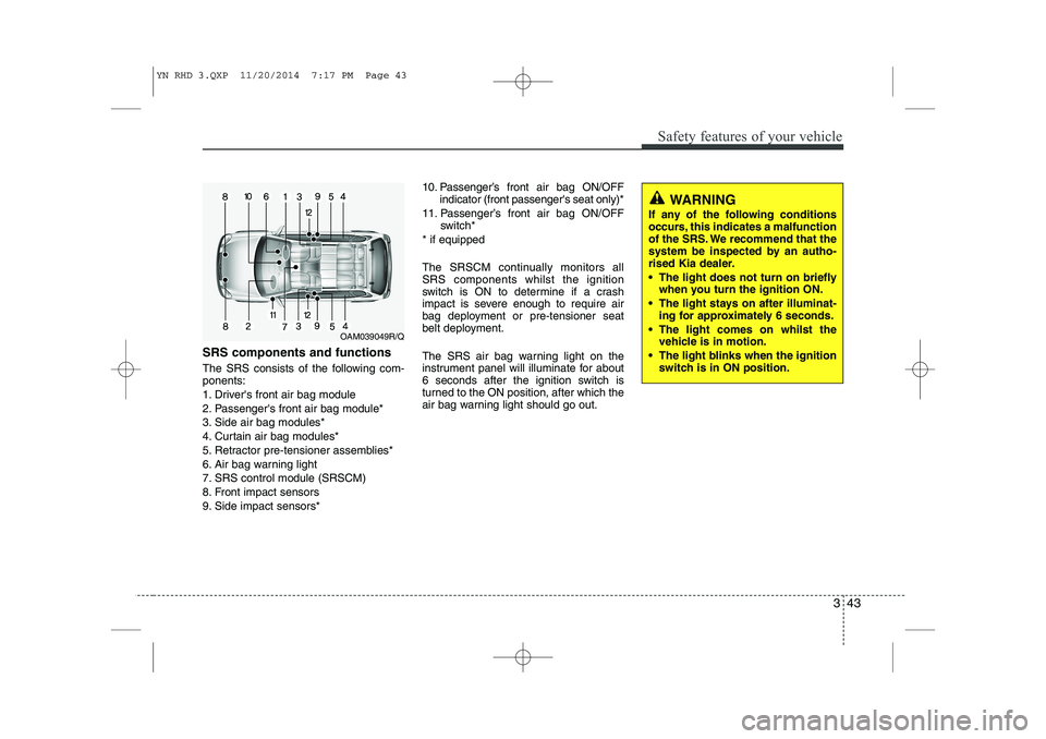
The SRS consists of the following com- ponents:
1. Driver's front air bag module
2. Passenger's front air bag module*
3. Side air bag modules*
4. Curtain air bag modules*
5. Retractor pre-tensioner assemblies*
6. Air bag warning light
7. SRS control module (SRSCM)
8. Front impact sensors
9. Side impact sensors*10. Passenger’s front air bag ON/OFF
indicator (front passenger's seat only)*
11. Passenger’s front air bag ON/OFF switch*
* if equipped
The SRSCM continually monitors all SRS components whilst the ignition
switch is ON to determine if a crash
impact is severe enough to require air
bag deployment or pre-tensioner seat
belt deployment.
The SRS air bag warning light on the
instrument panel will illuminate for about
6 seconds after the ignition switch is
turned to the ON position, after which the
air bag warning light should go out.
WARNING
If any of the following conditions
occurs, this indicates a malfunction
of the SRS. We recommend that the
system be inspected by an autho-
rised Kia dealer.
The light does not turn on briefly when you turn the ignition ON.
The light stays on after illuminat- ing for approximately 6 seconds.
The light comes on whilst the vehicle is in motion.
The light blinks when the ignition switch is in ON position.
OAM039049R/Q
YN RHD 3.QXP 11/20/2014 7:17 PM Page 43