climate control Lancia Delta 2012 Owner handbook (in English)
[x] Cancel search | Manufacturer: LANCIA, Model Year: 2012, Model line: Delta, Model: Lancia Delta 2012Pages: 295, PDF Size: 8.29 MB
Page 65 of 295

1
KNOWING YOUR CAR63
Heated rear window and door mirrors
demisting/defrosting fig. 26
Press button F
(to activate; when this function is acti-
vated, the button LED lights up.
This function is timed and will turn off automatically af-
ter 20 minutes. Press the button
(again to switch the
function off.
IMPORTANT Do not apply stickers on the inside of the
rear window over the heating filaments to avoid damage
that might cause it to stop working properly.
IMPORTANT Press
Tto introduce air from the out-
side (in this case the LED on the button is off).Rapid front window demisting/defrosting
(MAX-DEF function) fig. 26
Press button G
-to automatically activate the timed
operation of all the functions required to rapidly demist/
defrost the windscreen and front side windows.
The functions are:
❍climate control compressor engagement (with an out-
side temperature of above 4 °C);
❍switching off, if previously on, of the interior air re-
circulation (LED on button
Toff);
❍switching on of heated rear window (LED on button
-on) and door mirror heater coils;
❍air temperature set to maximum;
❍activation of air flow.
Page 66 of 295

64KNOWING YOUR CAR
Activation of air recirculation and enablement
of AQS (Air Quality System) fig. 26
Press button
T.
Internal air recirculation is carried out according to three
possible operating modes:
❍automatic control, signalled by the AQS sign on the
display and the LED on button
Tbeing off;
❍permanently off (air recirculation always off with in-
troduction of external air), indicated by the LED on
button
Tbeing off;
❍permanently on (air recirculation always on), sig-
nalled by the LED on button
Tbeing lit up.
When OFF is pressed, the climate control system auto-
matically activates air recirculation (the LED on button
Tis on). It is still possible to activate outside air re-
circulation (LED on the button is off) and vice versa, by
pressing button
T.
With the OFF button pressed (LED on the button is lit
up), it is not possible to enable the AQS (Air Quality Sys-
tem) function.IMPORTANT The internal air recirculation system makes
it possible to reach the required heating or cooling con-
ditions faster. It is not advisable to switch the air recir-
culation on when it is rainy/cold or the windows might
mist up, especially if the climate control is not turned on.
It is advisable to switch the internal air recirculation on
while standing in queues or in tunnels to prevent the in-
troduction of polluted air. Do not use the function for
a long time, particularly if there are many passengers on
board, to prevent the windows from misting up.
Enabling the AQS (Air Quality System) function
The AQS function (AQS appears on the display), auto-
matically activates internal air recirculation when the
outside air is polluted (e.g. in traffic queues and tunnels).
IMPORTANT With the AQS function active, after 15 con-
secutive minutes of the internal air recirculation system
functioning, the climate control system enables the intake
of outside air for approximately 1 minute to change the
air in the passenger compartment. This takes place re-
gardless of the pollution level of the outside air.
Page 67 of 295

1
KNOWING YOUR CAR65
Switching the climate control compressor on/off
I-fig. 26
Press button
❄to switch on the climate control system
compressor.
Compressor engagement
❍the LED on button
❄is lit up;
❍symbol
❄is shown on the display.
Compressor off
❍the LED on button
❄is off;
❍symbol
❄off on the display;
❍internal air recirculation is excluded;
❍the AQS function is disabled.
With the climate control compressor switched off, air can-
not be introduced into the passenger compartment at
a lower temperature than the outside temperature; in this
case the
❄symbol on the display will flash.
The deactivation of the climate control compressor is
memorised even after the engine has stopped. To turn the
climate control compressor back on, press button
❄again
or press AUTO: if you press AUTO, the other manual set-
tings will be cancelled.
EXTERNAL LIGHTS
The left-hand stalk operates most of the external lights.
The ignition key has to be in the MAR position for the ex-
terior lights to come on. The instrument panel and the
various dashboard controls will come on with the exter-
nal lights.
DAYTIME RUNNING LIGHTS (DRL)
(for versions/markets where provided)
With the ignition key turned to MAR and the twist switch
turned to position Othe daytime running lights are au-
tomatically activated; the other lights and interior light-
ing remain off. The automatic operation of the day lights
can be activated/deactivated via the display menu (see
“Display” paragraph in this chapter). If the daytime run-
ning lights are deactivated, no light comes on when the
twist switch is turned to O.
fig. 27L0E0019m
Page 124 of 295
122KNOWING YOUR CAR
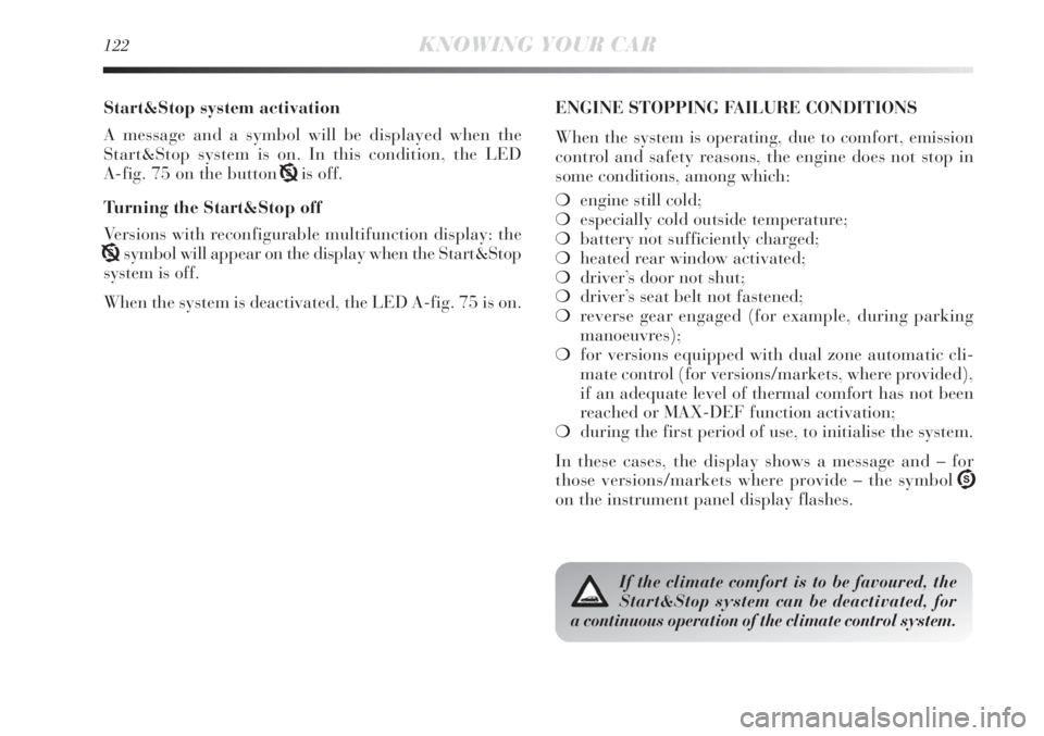
Start&Stop system activation
A message and a symbol will be displayed when the
Start&Stop system is on. In this condition, the LED
A-fig. 75 on the button Tis off.
Turning the Start&Stop off
Versions with reconfigurable multifunction display: the
Tsymbol will appear on the display when the Start&Stop
system is off.
When the system is deactivated, the LED A-fig. 75 is on.ENGINE STOPPING FAILURE CONDITIONS
When the system is operating, due to comfort, emission
control and safety reasons, the engine does not stop in
some conditions, among which:
❍engine still cold;
❍especially cold outside temperature;
❍battery not sufficiently charged;
❍heated rear window activated;
❍driver’s door not shut;
❍driver’s seat belt not fastened;
❍reverse gear engaged (for example, during parking
manoeuvres);
❍for versions equipped with dual zone automatic cli-
mate control (for versions/markets, where provided),
if an adequate level of thermal comfort has not been
reached or MAX-DEF function activation;
❍during the first period of use, to initialise the system.
In these cases, the display shows a message and – for
those versions/markets where provide – the symbol U
on the instrument panel display flashes.
If the climate comfort is to be favoured, the
Start&Stop system can be deactivated, for
a continuous operation of the climate control system.
Page 185 of 295
3
STARTING AND DRIVING183
FUEL SAVINGS
Here are some useful tips to save fuel and minimise harm-
ful emissions of CO
2and other pollutants (nitric oxides,
unburnt hydrocarbons, fine dusts etc…).
GENERAL CONSIDERATIONS
Car maintenance
Have checks and adjustments carried out in accordance
with the “Scheduled Servicing Plan”.
Ty r e s
Check the pressure of the tyres routinely at an interval
of no more than 4 weeks: if the pressure is too low, con-
sumption levels increase as resistance to rolling is higher.
Unnecessary loads
Do not travel with an overloaded boot. The weight of the
car (especially when driving in town) and its ride greatly
affects consumption and stability.Accessories installed on longitudinal bars
Remove accessories like: roof racks, ski racks, luggage
container, etc. from the roof if they are no longer used.
These accessories lower air penetration and adversely af-
fect consumption levels. When transporting particularly
large objects, use a trailer if possible.
Electric devices
Use electric devices only for the amount of time needed.
The heated rear window, additional headlights, wind-
screen wipers and heater fan need a considerable amount
of energy, therefore a higher requirement of current in-
volves an increase of fuel consumption (up to +25%
in the urban cycle).
Climate control system
Air conditioning leads to higher fuel consumption (on av-
erage up to +20%). If the temperature outside permits,
try and use the air vents.
Devices for aerodynamic control
The use of non-certified aerodynamic items may ad-
versely affect air drag and fuel consumption levels.
Page 225 of 295

IN AN EMERGENCY223
4
FUSE SUMMARY TABLE
F12
F12
F13
F13
F31
F33
F34
F35
F36
F37
F38
F39
F40
F417.5
15
7.5
15
5
20
20
5
20
7.5
10
10
30
7.538
38
38
38
38
38
38
38
38
38
38
38
38
38
USERS FUSE AMPS FIGURE
Right dipped beam headlight
Right dipped beam headlight (Xenon gas discharge bulb)
Left dipped beam headlight, headlight alignment corrector
Left dipped beam headlight (Xenon gas discharge bulb)
Climate control system fan relay coil, body computer
Left rear window winder
Right rear window winder
Reversing lights, engine compartment junction unit relay coils,
brake light pedal control (normally closed contact),
water in diesel sensor, air flow meter/control on clutch pedal
and brake servo pressure sensor (1.4 Turbo Multi Air versions)
Central locking system control unit, fuel flap,
dead lock, tailgate release
Third brake light, instrument panel, Adaptive Headlights Node
(1.4 Turbo Multi Air versions excluded), control unit on left hand
gas discharge headlight (1.4 Turbo Multi Air versions excluded)
Front roof lights, rear central roof light, driver side and passenger side sun
visor lights, luggage compartment roof light, glove compartment courtesy
light (Platinum trim level with optional sun roof - excluding MultiAir version)
Radio wiring/Radio/Radio Navigator (excluding MultiAir versions),
Blue&Me
TMNode, alarm siren, alarm system on roof light, climate control
unit, tyre pressure monitoring system control unit, diagnosis socket connector,
rear roof lights, voltage stabiliser (MultiAir versions without optional HI-FI)
Heated rear window
Electric door mirror demisters, demisters on windscreen jets
Page 226 of 295
224IN AN EMERGENCY
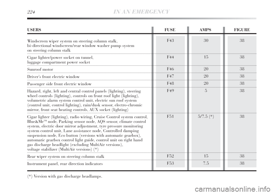
38
38
38
38
38
38
38
38
38F43
F44
F46
F47
F48
F49
F51
F52
F5330
15
20
20
20
5
5/7.5 (*)
15
7.5
USERS FUSE AMPS FIGURE
Windscreen wiper system on steering column stalk,
bi-directional windscreen/rear window washer pump system
on steering column stalk
Cigar lighter/power socket on tunnel,
luggage compartment power socket
Sunroof motor
Driver’s front electric window
Passenger side front electric window
Hazard, right, left and central control panels (lighting), steering
wheel controls (lighting), controls on front roof light (lighting),
volumetric alarm system control unit, electric sun roof system
(control unit, control lighting), rain/dusk sensor, electro-chromic
mirror, front seat heating controls, AUX socket (lighting)
Cigar lighter (lighting), radio wiring, Cruise Control system control,
Blue&Me
TMnode, Parking sensor node, AQS sensor, climate control
system, electric door mirror adjustment, tyre pressure monitoring
system control unit, Lane assistance node, Controlled damping
suspension node, Eco button (versions with automatic gearbox),
automatic gearbox control light guide, control unit on right hand
gas discharge headlight (excluding MultiAir versions),
voltage stabilizer (MultiAir versions) (*)
Rear wiper system on steering column stalk
Instrument panel, rear direction indicators
(*) Version with gas discharge headlamps.
Page 227 of 295
IN AN EMERGENCY225
4
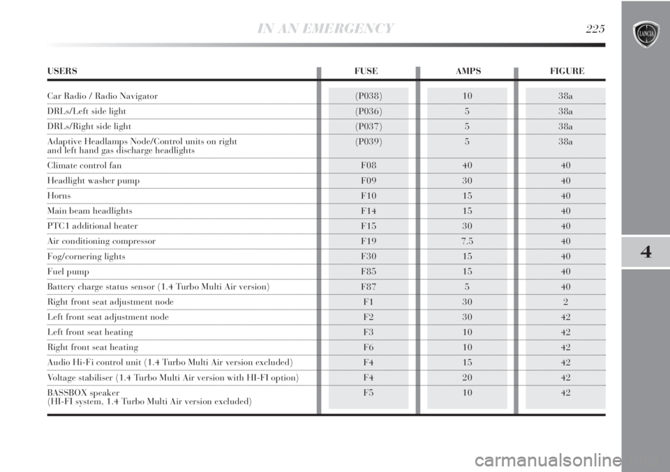
38a
38a
38a
38a
40
40
40
40
40
40
40
40
40
2
42
42
42
42
42
42(P038)
(P036)
(P037)
(P039)
F08
F09
F10
F14
F15
F19
F30
F85
F87
F1
F2
F3
F6
F4
F4
F510
5
5
5
40
30
15
15
30
7.5
15
15
5
30
30
10
10
15
20
10
USERS FUSE AMPS FIGURE
Car Radio / Radio Navigator
DRLs/Left side light
DRLs/Right side light
Adaptive Headlamps Node/Control units on right
and left hand gas discharge headlights
Climate control fan
Headlight washer pump
Horns
Main beam headlights
PTC1 additional heater
Air conditioning compressor
Fog/cornering lights
Fuel pump
Battery charge status sensor (1.4 Turbo Multi Air version)
Right front seat adjustment node
Left front seat adjustment node
Left front seat heating
Right front seat heating
Audio Hi-Fi control unit (1.4 Turbo Multi Air version excluded)
Voltage stabiliser (1.4 Turbo Multi Air version with HI-FI option)
BASSBOX speaker
(HI-FI system, 1.4 Turbo Multi Air version excluded)
Page 234 of 295
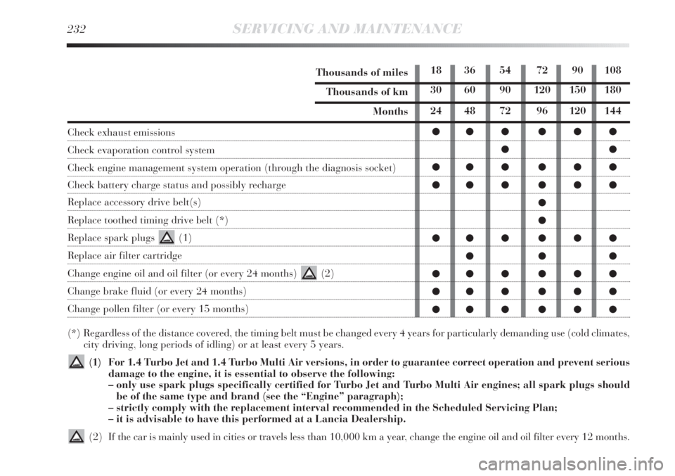
232SERVICING AND MAINTENANCE
Thousands of miles
Thousands of km
Months
Check exhaust emissions
Check evaporation control system
Check engine management system operation (through the diagnosis socket)
Check battery charge status and possibly recharge
Replace accessory drive belt(s)
Replace toothed timing drive belt (*)
Replace spark plugs (1)
Replace air filter cartridge
Change engine oil and oil filter (or every 24 months) (2)
Change brake fluid (or every 24 months)
Change pollen filter (or every 15 months)
(*) Regardless of the distance covered, the timing belt must be changed every 4 years for particularly demanding use (cold climates,
city driving, long periods of idling) or at least every 5 years.
(1) For 1.4 Turbo Jet and 1.4 Turbo Multi Air versions, in order to guarantee correct operation and prevent serious
damage to the engine, it is essential to observe the following:
– only use spark plugs specifically certified for Turbo Jet and Turbo Multi Air engines; all spark plugs should
be of the same type and brand (see the “Engine” paragraph);
– strictly comply with the replacement interval recommended in the Scheduled Servicing Plan;
– it is advisable to have this performed at a Lancia Dealership.
(2) If the car is mainly used in cities or travels less than 10,000 km a year, change the engine oil and oil filter every 12 months.
18 36 54 72 90 108
30 60 90 120 150 180
24 48 72 96 120 144
●●● ●●●
●●
●●● ●●●
●●● ●●●
●
●
●●● ●●●
●●●
●●● ●●●
●●● ●●●
●●● ●●●
Page 281 of 295

TECHNICAL SPECIFICATIONS279
6
FUEL CONSUMPTION
The fuel consumption figures given in the table below are
determined on the basis of the type-approval tests laid
down by specific European Directives.
The procedures below are followed for measuring con-
sumption:
❍urban cycle: cold starting followed by driving that
simulates urban use of the car;
❍extra-urban cycle: frequent accelerations in all gears,
simulating extra-urban use of the vehicle: speed varies
between 0 and 120 km/h;
❍combined consumption: calculated with a weighting
of about 37% of urban cycle consumption and about
63% of extra-urban consumption.IMPORTANT The type of route, traffic situations,
weather conditions, driving style, general conditions of
the car, trim level/equipment/accessories, load, climate
control system, roof rack, other situations that affect air
drag may lead to different fuel consumption levels than
those measured.
FUEL CONSUMPTION ACCORDING TO THE CURRENT EUROPEAN DIRECTIVE (litres/100 km)
1.4 Turbo Jet
120 HP1.4 Turbo
Multi Air1.6 Multijet
105 HP1.6 Multijet
115 HP/120 HP
1.9 Twin Turbo
Multijet2.0 Multijet
Urban8.17.35.87.36.7
Extra-urban5.24.84.04.74.2
6.35.74.75.75.1Combined5.7
3.9
4.6