Lancia Delta 2013 Owner handbook (in English)
Manufacturer: LANCIA, Model Year: 2013, Model line: Delta, Model: Lancia Delta 2013Pages: 295, PDF Size: 8.29 MB
Page 221 of 295

IN AN EMERGENCY219
4
REPLACING FUSES
GENERAL INFORMATION
Fuses protect the electric system: they cut in (i.e. they
blow) in the event of a failure or improper action on the
system. Check the state of the corresponding fuse when
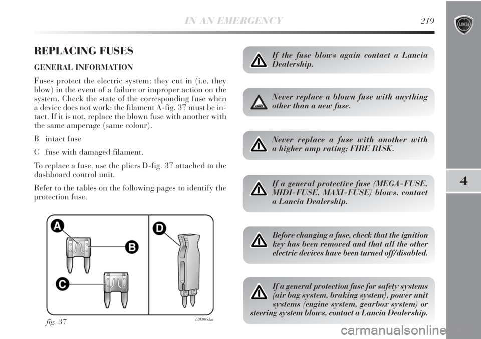
a device does not work: the filament A-fig. 37 must be in-
tact. If it is not, replace the blown fuse with another with
the same amperage (same colour).
B intact fuse
C fuse with damaged filament.
To replace a fuse, use the pliers D-fig. 37 attached to the
dashboard control unit.
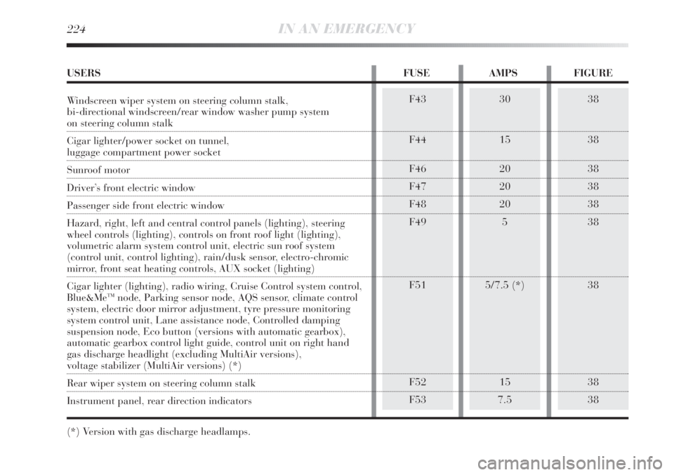
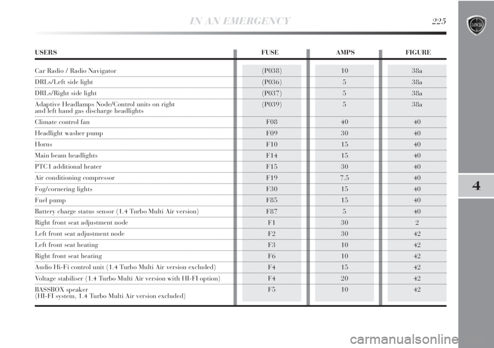
Refer to the tables on the following pages to identify the
protection fuse.
fig. 37L0E0085m
If the fuse blows again contact a Lancia
Dealership.
Never replace a blown fuse with anything
other than a new fuse.
Never replace a fuse with another with
a higher amp rating; FIRE RISK.
If a general protective fuse (MEGA-FUSE,
MIDI-FUSE, MAXI-FUSE) blows, contact
a Lancia Dealership.
Before changing a fuse, check that the ignition
key has been removed and that all the other
electric devices have been turned off/disabled.
If a general protection fuse for safety systems
(air bag system, braking system), power unit
systems (engine system, gearbox system) or
steering system blows, contact a Lancia Dealership.
Page 222 of 295

220IN AN EMERGENCY
fig. 38L0E0209m
FUSE LOCATION
Dashboard fuse box
To access the fuses you must remove the press-fitted cover A. The fuse box shown in fig. 38 is located in the lower
area next to the pedal unit.
Page 223 of 295

IN AN EMERGENCY221
4
Engine compartment fuse box fig. 39 and 40
A second fuse box is located on the right side of the en-
gine compartment, next to the battery. To access this fuse
box release the side tabs and remove cover L. The ID
number of the electrical component corresponding to
each fuse can be found on the back of the cover.
fig. 39L0E0088mfig. 38aL0E0211m
If you need to wash the engine compartment,
take care not to directly hit the engine com-
partment fuse box with the jet of water.
Additional fuses (1.4 Turbo Multi Air versions)
On the 1.4 Turbo Multi Air versions there are four addi-
tional fuses (fig. 38a) next to the dashboard junction unit.
Page 224 of 295

222IN AN EMERGENCY
Luggage compartment fuse box fig. 41 and 42
To gain access to the fuse box located on the left side of
luggage compartment open the relevant inspection lid
fig. 41.
fig. 42L0E0115m
fig. 41L0E0114m
fig. 40L0E0210m
Page 225 of 295

IN AN EMERGENCY223
4
FUSE SUMMARY TABLE
F12
F12
F13
F13
F31
F33
F34
F35
F36
F37
F38
F39
F40
F417.5
15
7.5
15
5
20
20
5
20
7.5
10
10
30
7.538
38
38
38
38
38
38
38
38
38
38
38
38
38
USERS FUSE AMPS FIGURE
Right dipped beam headlight
Right dipped beam headlight (Xenon gas discharge bulb)
Left dipped beam headlight, headlight alignment corrector
Left dipped beam headlight (Xenon gas discharge bulb)
Climate control system fan relay coil, body computer
Left rear window winder
Right rear window winder
Reversing lights, engine compartment junction unit relay coils,
brake light pedal control (normally closed contact),
water in diesel sensor, air flow meter/control on clutch pedal
and brake servo pressure sensor (1.4 Turbo Multi Air versions)
Central locking system control unit, fuel flap,
dead lock, tailgate release
Third brake light, instrument panel, Adaptive Headlights Node
(1.4 Turbo Multi Air versions excluded), control unit on left hand
gas discharge headlight (1.4 Turbo Multi Air versions excluded)
Front roof lights, rear central roof light, driver side and passenger side sun
visor lights, luggage compartment roof light, glove compartment courtesy
light (Platinum trim level with optional sun roof - excluding MultiAir version)
Radio wiring/Radio/Radio Navigator (excluding MultiAir versions),
Blue&Me
TMNode, alarm siren, alarm system on roof light, climate control
unit, tyre pressure monitoring system control unit, diagnosis socket connector,
rear roof lights, voltage stabiliser (MultiAir versions without optional HI-FI)
Heated rear window
Electric door mirror demisters, demisters on windscreen jets
Page 226 of 295

224IN AN EMERGENCY
38
38
38
38
38
38
38
38
38F43
F44
F46
F47
F48
F49
F51
F52
F5330
15
20
20
20
5
5/7.5 (*)
15
7.5
USERS FUSE AMPS FIGURE
Windscreen wiper system on steering column stalk,
bi-directional windscreen/rear window washer pump system
on steering column stalk
Cigar lighter/power socket on tunnel,
luggage compartment power socket
Sunroof motor
Driver’s front electric window
Passenger side front electric window
Hazard, right, left and central control panels (lighting), steering
wheel controls (lighting), controls on front roof light (lighting),
volumetric alarm system control unit, electric sun roof system
(control unit, control lighting), rain/dusk sensor, electro-chromic
mirror, front seat heating controls, AUX socket (lighting)
Cigar lighter (lighting), radio wiring, Cruise Control system control,
Blue&Me
TMnode, Parking sensor node, AQS sensor, climate control
system, electric door mirror adjustment, tyre pressure monitoring
system control unit, Lane assistance node, Controlled damping
suspension node, Eco button (versions with automatic gearbox),
automatic gearbox control light guide, control unit on right hand
gas discharge headlight (excluding MultiAir versions),
voltage stabilizer (MultiAir versions) (*)
Rear wiper system on steering column stalk
Instrument panel, rear direction indicators
(*) Version with gas discharge headlamps.
Page 227 of 295

IN AN EMERGENCY225
4
38a
38a
38a
38a
40
40
40
40
40
40
40
40
40
2
42
42
42
42
42
42(P038)
(P036)
(P037)
(P039)
F08
F09
F10
F14
F15
F19
F30
F85
F87
F1
F2
F3
F6
F4
F4
F510
5
5
5
40
30
15
15
30
7.5
15
15
5
30
30
10
10
15
20
10
USERS FUSE AMPS FIGURE
Car Radio / Radio Navigator
DRLs/Left side light
DRLs/Right side light
Adaptive Headlamps Node/Control units on right
and left hand gas discharge headlights
Climate control fan
Headlight washer pump
Horns
Main beam headlights
PTC1 additional heater
Air conditioning compressor
Fog/cornering lights
Fuel pump
Battery charge status sensor (1.4 Turbo Multi Air version)
Right front seat adjustment node
Left front seat adjustment node
Left front seat heating
Right front seat heating
Audio Hi-Fi control unit (1.4 Turbo Multi Air version excluded)
Voltage stabiliser (1.4 Turbo Multi Air version with HI-FI option)
BASSBOX speaker
(HI-FI system, 1.4 Turbo Multi Air version excluded)
Page 228 of 295

226IN AN EMERGENCY
BATTERY RECHARGING
IMPORTANT The battery recharging procedure is given
as information only. You are advised to go to a Lancia
Dealership to have this operation performed.
Charging should be slow at a low ampere rating for ap-
proximately 24 hours. Charging for a longer time may
damage the battery.
VERSIONS WITHOUT Start&Stop SYSTEM
(for versions/markets, where provided)
Charge the battery as follows:
❍disconnect the negative battery terminal;
❍connect the charger leads to the battery terminals, ob-
serving the polarity;
❍turn on the charger;
❍when you have finished, turn the charger off before
disconnecting the battery;
❍reconnect the negative battery terminal.VERSIONS WITH Start&Stop SYSTEM fig. 43
(for versions/markets, where provided)
To charge, proceed as follows:
❍detach the connector A (by pressing button B) from
sensor C for monitoring the status of the battery in-
stalled on the negative battery pole D;
fig. 43L0E0199m
Page 229 of 295

IN AN EMERGENCY227
4
Battery fluid is poisonous and corrosive:
avoid contact with your skin and eyes. The
battery recharging operation must be per-
formed in a ventilated place, away from naked
flames or possible sources of sparks to avoid the
risk of explosion and fire.
Don’t try to recharge a frozen battery: If the
battery was frozen, have it inspected by
skilled personnel before recharging to check
that the internal elements are not damaged and that
the casing is not cracked, which causes the risk of
leakage of poisonous, corrosive acid.
JACKING THE CAR
If the car is to be lifted, go to a Lancia Dealership which
is equipped with the arm hoist or workshop lift.
TOWING THE CAR
The tow ring, which is provided with the car, is housed
in the tool box, under the boot mat.
FASTENING THE TOW RING fig. 44-45
Proceed as follows:
❍release cap A;
❍take the tow ring B from its housing in the tool sup-
port;
❍screw the ring onto the rear or front threaded pin.
fig. 44L0E0297m
❍connect the positive cable to the positive battery ter-
minal E and the negative terminal to the sensor D as
shown in the figure;
❍turn on the charger. Turn the device off after recharg-
ing;
❍after having disconnected the recharging device, re-
connect the connector A to the sensor C as shown in
the figure.
Page 230 of 295

228IN AN EMERGENCY
When towing, remember that without the
help of the brake servo and electric power
steering, a greater effort is required on the
pedal and steering wheel. Do not use flexible ca-
bles when towing and avoid jerky movements.
While towing, make sure not to damage parts in
contact with the car. When towing the vehicle, it is
compulsory to respect specific highway code reg-
ulations relating to the tow hook and procedures for
towing on the road. Do not start the engine while
towing the car. Before tightening the ring clean the
threaded housing thoroughly. Make sure that the
ring is securely fastened before towing the car.
The front and rear tow hooks must only be
used for emergency situations on the road.
The car may be towed for short distances
when a dedicated device is used in compliance with
the Highway Code (rigid bar), and in order to move
the vehicle on the road in preparation for towing by
a tow truck. Tow hooks MUST NOT be used to tow
vehicles off the road or where there are obstacles
and/or for towing operations using cables or other
non-rigid devices. Respecting the above conditions,
towing must take place with two vehicles (one tow-
ing, the other towed) aligned as much as possible
along the same centre line.
fig. 45L0E0091m
Before towing, turn the ignition key to MAR
and then to STOP without removing it. The
steering column will automatically lock
when the key is removed and the wheels cannot be
steered.