key Lancia Flavia 2012 Owner handbook (in English)
[x] Cancel search | Manufacturer: LANCIA, Model Year: 2012, Model line: Flavia, Model: Lancia Flavia 2012Pages: 233, PDF Size: 2.61 MB
Page 39 of 233
Knee Impact Bolsters
The Knee Impact Bolsters help pro-
tect the knees of the driver and the
front passenger, and position front oc-
cupants for the best interaction with
the Advanced Front Air Bags.
Along with seat belts and pretension-
ers, Advanced Front Air Bags work
with the knee bolsters to provide im-
proved protection for the driver and
front passenger. Side air bags also
work with seat belts to improve occu-
pant protection.
AIR BAG DEPLOYMENT
SENSORS AND CONTROLS
Occupant Restraint Controller
(ORC)
TheORC is part of a regulated safety
system required for this vehicle.
The ORC determines if deployment of
the front and/or side air bags in a
frontal or side collision is required.
Based on the impact sensor's signals,
a central electronic ORC deploys the
Advanced Front Air Bags, Supple-
mental Seat-Mounted Side Air Bags
(SAB), and front seat belt pretension- ers, as required, depending on several
factors, including the severity and
type of impact.
Advanced Front Air Bags are designed
to provide additional protection by
supplementing the seat belts in cer-
tain frontal collisions depending on
several factors, including the severity
and type of collision. Advanced Front
Air Bags are not expected to reduce
the risk of injury in rear, side, or roll-
over collisions.
The Advanced Front Air Bags will not
deploy in all frontal collisions, includ-
ing some that may produce substan-
tial vehicle damage — for example,
some pole collisions, truck under-
rides, and angle offset collisions. On
the other hand, depending on the type
and location of impact, Advanced
Front Air Bags may deploy in crashes
with little vehicle front-end damage
but that produce a severe initial decel-
eration.
The side air bags will not deploy in all
side collisions. Side air bag deploy-
ment will depend on the severity and
type of collision.Because air bag sensors measure ve-
hicle deceleration over time, vehicle
speed and damage by themselves are
not good indicators of whether or not
an air bag should have deployed.
Seat belts are necessary for your pro-
tection in all collisions, and also are
needed to help keep you in position,
away from an inflating air bag.
The ORC monitors the readiness of
the electronic parts of the air bag sys-
tem whenever the ignition switch is in
the START or ON/RUN position. If
the key is in the OFF position, in the
ACC position, or not in the ignition,
the air bag system is not on and the air
bags will not inflate.
The ORC contains a backup power
supply system that may deploy the air
bags even if the battery loses power or
it becomes disconnected prior to de-
ployment.
Also, the ORC turns on the
Air Bag Warning Light in
the instrument panel for
approximately four to eight
seconds for a self-check when the ig-
nition is first turned on. After the self-32
Page 41 of 233
SAB air bags are a supplement to the
seat belt restraint system. Occupants,
including children who are up against
or very close to SAB air bags can be
seriously injured or killed. Occupants,
especially children, should not lean on
or sleep against the door, side win-
dows, or area where the SAB air bags
inflate, even if they are in an infant or
child restraint. Always sit upright as
possible with your back against the
seat back, use the seat belts properly,
and use the appropriate sized child
restraint, infant restraint or booster
seat recommended for the size and
weight of the child.
Front And Side Impact Sensors
In front and side impacts, impact sen-
sors can aid the ORC in determining
appropriate response to impact
events.Enhanced Accident Response
System
In the event of an impact causing air
bag deployment, if the communica-
tion network remains intact, and the
power remains intact, depending on
the nature of the event the ORC will
determine whether to have the En-
hanced Accident Response System
perform the following functions:
Cut off fuel to the engine.
Flash hazard lights as long as the
battery has power or until the igni-
tion key is turned off.
Turn on the interior lights, which remain on as long as the battery has
power or until the ignition key is
removed.
Unlock the doors automatically.
In order to reset the Enhanced Acci-
dent Response System functions after
an event, the ignition switch must be
changed from IGN ON to IGN OFF.
If A Deployment Occurs
The Advanced Front Air Bags are de-
signed to deflate immediately after
deployment. NOTE:
Front and/or side air bags will not
deploy in all collisions. This does
not mean something is wrong with
the air bag system.
If you do have a collision, which de-
ploys the air bags, any or all of the
following may occur:
The nylon air bag material may
sometimes cause abrasions and/or
skin reddening to the driver and
front passenger as the air bags de-
ploy and unfold. The abrasions are
similar to friction rope burns or those
you might get sliding along a carpet
or gymnasium floor. They are not
caused by contact with chemicals.
They are not permanent and nor-
mally heal quickly. However, if you
haven't healed significantly within a
few days, or if you have any blister-
ing, see your doctor immediately.
34
Page 44 of 233

manufacturer, other parties, such as
law enforcement, that have the spe-
cial equipment, can read the informa-
tion if they have access to the vehicle
or the EDR.
CHILD RESTRAINTS
Everyone in your vehicle needs to be
buckled up all the time, including ba-
bies and children.
Children 12 years or younger should
ride properly buckled up in a rear
seat, if available. According to crash
statistics, children are safer when
properly restrained in the rear seats,
rather than in the front.
WARNING!
In a collision, an unrestrainedchild, even a tiny baby, can be-
come a projectile inside the ve-
hicle. The force required to hold
even an infant on your lap could
become so great that you could
not hold the child, no matter how
strong you are. The child and oth-
ers could be badly injured. Any
child riding in your vehicle should
be in a proper restraint for the
child's size.
(Continued)
WARNING!(Continued)
Occupants, especially children,
should not lean on or sleep against
the door, side windows, or area
where the SAB air bags inflate,
even if they are in an infant or
child restraint.
There are different sizes and types of
restraints for children from newborn
size to the child almost large enough
for an adult safety belt. Always check
the child seat owner's manual to en-
sure you have the correct seat for your
child. Use the restraint that is correct
for your child.
Universal Child Seating Position Chart
Mass Group Front PassengerRear Outboard
Group up to 10 kg XU
Group 0+ up to 13 kg XU
Group I 9 to 18 kg XU
Group II 15 to 25 kg XU
Group III 22 to 36 kg XU
Key of letters used in the table above
U = Suitable for “universal” category restraints approved for use in this mass group.
X = Seat position not suitable for children in this mass group.
37
Page 45 of 233

Vehicle ISOFIX Positions Chart
Mass Group Size
Class Fixture Front Pas-
senger Rear Out-
board Rear Cen-
ter Intermedi-
ate Out- board Intermedi-
ate Center Other
Sites
Carrycot F ISO/L1 X **1UF X X X X
G ISO/L2 X **1UF X X X X (1) X X X X X X
0 — up to 10 kg E ISO/R1 X 1UF X X X X
(1) X X X X X X
0+ — up to 13 kg E ISO/R1 X 1UF X X X X
D ISO/R2 X 1UF X X X X C ISO/R3 X *1UF X X X X (1) X X X X X X
I – 9 to 18 kg D ISO/R2 X 1UF X X X X
C ISO/R3 X *1UF X X X X B ISO/F2 X 1UF X X X X
B1 ISO/F2X X 1UF X X X X A ISO/F3 X 1UF X X X X (1) X X X X X X
II – 15 to 25 kg (1) X X X X X X
III – 22 to 36 kg (1) X X X X X X
Key of letters used in the table above
(1) = For the CRS which do not carry the ISO/XX size class identification (A to G), for the applicable mass group, the
car manufacturer shall indicate the vehicle specific ISOFIX child restraint system(s) recommended for each position.
1UF = Suitable for ISOFIX forward child restraint systems of universal category approved for use in the mass group.
X = ISOFIX position not suitable for ISOFIX child restraint systems in this mass group and/or this size class.
*1UF = With the seat in the mid-track position, seat back must be adjusted so that it does not touch the child seat.
**1UF = The Carrycot F & G can only be installed with the convertible top in the down position.
38
Page 60 of 233

CONVERTIBLE TOP
OPERATIONCAUTION!
Failure to follow these cautions may
cause interior water damage, stains
or mildew on the top material:
Avoid high-pressure car washes,as they can damage the top mate-
rial. Also, increased water pres-
sure may force water past the
weather strips.
Remove any standing water from
the top and dry the surface before
opening it. Operating the top,
opening a door or lowering a win-
dow while the top is wet may al-
low water to drip into the vehicles
interior.
Use care when washing the ve-
hicle, water pressure directed at
the weather strip seals may cause
water to leak into the vehicles in-
terior.
WARNING!
The convertible top does not provide
the structural protection that a rein-
forced metal roof does and the fabric
top cannot be expected to prevent
the ejection of the occupants in a
collision. Therefore, it is important
that all occupants wear their seat
belts at all times. Death or serious
injuries could occur if you are
ejected from the vehicle during a
collision.
You can lower or raise the power con-
vertible top from inside the vehicle or
lower the top remotely using the Re-
mote Keyless Entry (RKE) transmit-
ter. Either operation takes approxi-
mately 30 seconds. The entire
process, including unlatching or
latching the top at the windshield
header is automatic.
The top does take up some space in
the trunk when retracted. However,
the trunk will still hold a significant
amount of cargo. When operating the power convert-
ible top, the trunk lid will pivot at the
rear of the vehicle, swing open by the
rear window, and then pivot back-
ward. This allows room for the top to
retract into or unfold from its stowage
area in the trunk.
When lowering the top, the system
extends the hard tonneau cover,
which stows conveniently underneath
the trunk lid. The tonneau cover
closes the area between the rear seats
and the trunk lid to conceal the top
when stowed.
When raising the top, the system re-
tracts the hard tonneau cover back
into its stowage area underneath the
trunk lid.
To complete either operation, the
trunk lid returns to its normal posi-
tion and then latches.
Spring-loaded flipper doors, which
provide clearance for the linkage,
close off notches in the quarter trim
panels when the top is down.
53
Page 64 of 233
POWER CONVERTIBLE
TOP CONTROLS
The power top switch is located on the
front of the center console.
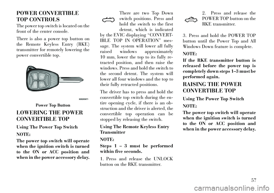
There is also a power top button on
the Remote Keyless Entry (RKE)
transmitter for remotely lowering the
power convertible top.
LOWERING THE POWER
CONVERTIBLE TOP
Using The Power Top Switch
NOTE:
The power top switch will operate
when the ignition switch is turned
to the ON or ACC position and
when in the power accessory delay.There are two Top Down
switch positions. Press and
hold the switch to the first
detent, which is indicated
by the EVIC displaying “CONVERT-
IBLE TOP IN OPERATION” mes-
sage. The system will lower all fully
raised windows approximately
10 mm, lower the top to its fully re-
tracted position, and then raise the
windows. Press and hold the switch to
the second detent. The system will
lower all four windows and the top to
their fully retracted positions.
The driver has to press and hold the
convertible top switch during the en-
tire opening cycle, if there is an ob-
struction and the driver is alerted, the
convertible top operation can be
stopped by releasing the switch.
Using The Remote Keyless Entry
Transmitter
NOTE:
Steps 1 – 3 must be performed
within five seconds.
1. Press and release the UNLOCK
button on the RKE transmitter. 2. Press and release the
POWER TOP button on the
RKE transmitter.
3. Press and hold the POWER TOP
button until the Power Top and All
Windows Down feature is complete.
NOTE:
If the RKE transmitter button is
released before the power top is
completely down steps 1–3 must be
performed again.
RAISING THE POWER
CONVERTIBLE TOP
Using The Power Top Switch
NOTE:
The power top switch will operate
when the ignition switch is turned
to the ON or ACC position and
when in the power accessory delay.
Power Top Button
57
Page 65 of 233
Press and hold the switch in
the Top Up position, “CON-
VERTIBLE TOP IN OP-
ERATION” message is dis-
played in the EVIC at this time. Keep
holding the switch until the operation
of raising the top and latching it is
complete, which is indicated by the
system also raising the windows and
displaying “CONVERTIBLE TOP
COMPLETE” message in the EVIC.
Using The Remote Keyless Entry
Transmitter
You cannot use the power top button
on the RKE transmitter to raise the
power convertible top. You must use
the power top switch inside the ve-
hicle to perform this operation.
Manually Raising
Raising the power convertible top
manually should only be performed
by an authorized dealer. In the event
that you experience a malfunction
when operating the power convertible
top:
1. Read all of the Notes, Cautions,
and Warning found under “Power Convertible Top Usage Precautions”
to verify all operating conditions are
met.
2. Check for Operation and Warning
Messages as described under “Power
Convertible Top Operation and Warn-
ing Messages.” If applicable, perform
the related action to correct the con-
dition present.
3. If Steps 1 and 2 do not resolve the
problem, refer to “Emergency Bypass
Mode”.
WIND STOP
The Wind Stop installs in the backseat
area of the vehicle. The Wind Stop
will not interfere with power top op-
eration. Therefore, it can remain in-
stalled when the top is up. However,
when not in use, the Wind Stop folds
to allow for convenient storage under-
neath the cargo shield in the trunk.
NOTE:
It is recommended that you lower
the convertible top before install-
ing or removing the Wind Stop.
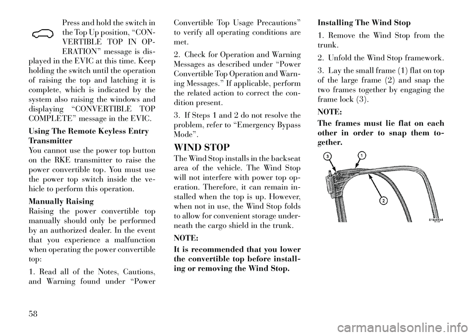
Installing The Wind Stop
1. Remove the Wind Stop from the
trunk.
2. Unfold the Wind Stop framework.
3. Lay the small frame (1) flat on top
of the large frame (2) and snap the
two frames together by engaging the
frame lock (3).
NOTE:
The frames must lie flat on each
other in order to snap them to-
gether.
58
Page 79 of 233
Redial
Press the
button to begin.
After the “Ready” prompt and the following beep, say “Redial”.
The Uconnect™ Phone will call the last number that was dialed from
your mobile phone.
NOTE:
This may not be the last number
dialed from the Uconnect™
Phone.
Call Continuation
Call continuation is the progression of
a phone call on the Uconnect™ Phone
after the vehicle ignition key has been
switched to OFF. Call continuation
functionality available on the vehicle
can be any one of three types:
After the ignition key is switched to OFF, a call can continue on the
Uconnect™ Phone either until the
call ends, or until a vehicle specific
time expires, or until the vehicle
battery condition dictates cessation
of the call on the Uconnect™ Phone
and transfer of the call to the mo-
bile phone. After the ignition key is switched to
OFF, a call can continue on the
Uconnect™ Phone for a certain du-
ration, after which the call is auto-
matically transferred from the
Uconnect™ Phone to the mobile
phone.
An active call is automatically transferred to the mobile phone af-
ter the ignition key is switched to
OFF.
UCONNECT™ PHONE
FEATURES
Language Selection
To change the language that the
Uconnect™ Phone is using:
Press the
button to begin.
After the “Ready” prompt and the following beep, say the name of the
language you wish to switch to
(English, Dutch, French, German,
Italian, or Spanish, if so equipped).
Continue to follow the system prompts to complete language se-
lection. After selecting one of the languages,
all prompts and voice commands will
be in that language.
NOTE:
After every Uconnect™ Phone lan-
guage change operation, only the
language-specific 32-name phone-
book is usable. The paired phone
name is not language-specific and
is usable across all languages.For command translations and alter-
nate commands in supported lan-
guages, refer to “Commands” in
“Voice Command System Operation”.
Emergency Assistance (for
versions/markets, where
provided)
If you are in an emergency and the
mobile phone is reachable:
Pick up the phone and manually
dial the emergency number for
your area.
72
Page 80 of 233

If the phone is not reachable and the
Uconnect™ Phone is operational, you
may reach the emergency number as
follows:
Press the
button to begin.
After the “Ready” prompt and the following beep, say “Emergency”
and the Uconnect™ Phone will in-
struct the paired mobile phone to
call the emergency number.
NOTE:
The default number is 112. The number dialed may not be ap-
plicable with the available mo-
bile service and area.
If supported, this number may be programmable on some sys-
tems. To do this, press the
button and say “Setup”, fol-
lowed by “Emergency”.
The Uconnect™ Phone does slightly lower your chances of
successfully making a phone
call as to that for the mobile
phone directly.
WARNING!
To use your Uconnect™ Phone Sys-
tem in an emergency, your mobile
phone must be:
turned on,
paired to the Uconnect™ System,
and have network coverage.
Breakdown Service (for
versions/markets, where
provided)
If you need Breakdown service:
Press the
button to begin.
After the “Ready” prompt and the following beep, say “Breakdown
service”.
NOTE:
The Breakdown service number
has to be setup before using. To
setup, press the
button and say
“Setup, Breakdown Service” and
follow prompts.
Paging
To learn how to page refer to “Work-
ing with Automated Systems”. Paging
works properly except for pagers of
certain companies which time out a
little too soon to work properly with
the Uconnect™ Phone. Voice Mail Calling
To learn how to access your voice
mail, refer to “Working with Auto-
mated Systems”.
Working With Automated Systems
This method is used in instances
where one generally has to press num-
bers on the mobile phone keypad
while navigating through an auto-
mated telephone system.
You can use your Uconnect™ Phone
to access a voice mail system or an
automated service, such as a paging
service or automated customer ser-
vice. Some services require immediate
response selection. In some instances,
that may be too quick for use of the
Uconnect™ Phone.
When calling a number with your
Uconnect™ Phone that normally re-
quires you to enter in a touch-tone
sequence on your mobile phone key-
pad, you can press the
button
and say the sequence you wish to en-
ter followed by the word “Send”. For
example, if required to enter your PIN
followed with a hash, (3 7 4 6 #), you
can press the
button and say, “3
73
Page 81 of 233
7 4 6 # Send”. Saying a number, or
sequence of numbers, followed by
“Send”, is also to be used for navigat-
ing through an automated customer
service center menu structure, and to
leave a number on a pager.
You can also send stored Uconnect™
Phonebook entries as tones for fast
and easy access to voice mail and
pager entries. To use this feature, dial
the number you wish to call and then
press the
button and say
“Send.” The system will prompt you
to enter the name or number and say
the name of the phonebook entry you
wish to send. The Uconnect™ Phone
will then send the corresponding
phone number associated with the
phonebook entry, as tones over the
phone.
NOTE:
You may not hear all of the tones due to mobile phone network
configurations; this is normal.
Some paging and voice mail sys- tems have system time out set-
tings that are too short and may
not allow the use of this feature. Barge In — Overriding Prompts
The “Voice Command” button can be
used when you wish to skip part of a
prompt and issue your voice com-
mand immediately. For example, if a
prompt is asking “Would you like to
pair a phone, clear a…,” you could
press the
button and say, “Pair
a Phone” to select that option without
having to listen to the rest of the voice
prompt.
Turning Confirmation Prompts
On/Off
Turning confirmation prompts off
will stop the system from confirming
your choices (e.g., the Uconnect™
Phone will not repeat a phone number
before you dial it).
Press thebutton to begin.
After the “Ready” prompt and the following beep, say:
� “Setup Confirmations Prompts On”
� “Setup Confirmations Prompts Off” Phone And Network Status
Indicators
If available on the radio and/or on a
premium display such as the
instru-
ment panel cluster, and supported by
your mobile phone, the Uconnect™
Phone will provide notification to in-
form you of your phone and network
status when you are attempting to
make a phone call using Uconnect™
Phone. The status is given for network
signal strength, phone battery
strength, etc.
Dialing Using The Mobile Phone
Keypad
You can dial a phone number with
your mobile phone keypad and still
use the Uconnect™ Phone (while di-
aling via the mobile phone keypad,
the user must exercise caution and
take precautionary safety measures).
By dialing a number with your paired
Bluetooth® mobile phone, the audio
will be played through your vehicle's
audio system. The Uconnect™ Phone
will work the same as if you dialed the
number using a Voice Command.
74