display Lancia Flavia 2012 Owner handbook (in English)
[x] Cancel search | Manufacturer: LANCIA, Model Year: 2012, Model line: Flavia, Model: Lancia Flavia 2012Pages: 233, PDF Size: 2.61 MB
Page 129 of 233

the headlights will turn on approxi-
mately 10 seconds after the wipers are
turned on. The headlights will also
turn off when the wipers are turned
off if they were turned on by this
feature. To make your selection, press
the SELECT button until ON or OFF
appears.
NOTE:
Turning the headlights on during
the daytime causes the instrument
panel lights to dim. To increase the
brightness, refer to “Lights” in
“Understanding The Features Of
Your Vehicle.”
Key Off Power Delay
When this feature is selected, the
power window switches, radio,
Uconnect™ phone, and power outlets
will remain active for up to 10 min-
utes after the ignition switch is turned
to the LOCK position. Opening either
front vehicle door will cancel this fea-
ture. To make your selection, press the
SELECT button until OFF, 45 sec, 5
min, or 10 min appears.Illumin. Approach
When this feature is selected, the
headlights will activate and remain on
for up to 90 seconds when the doors
are unlocked with the remote keyless
entry transmitter. To make your selec-
tion, press the SELECT button until
“OFF,” “30 sec,” “60 sec,” or
“90 sec” appears.
Display Units In
The EVIC and odometer can be
changed between English and Metric
units of measure. To make your selec-
tion, press and release the SELECT
button until “U.S.” or “METRIC” ap-
pears.
Compass Variance
Refer to “Compass Display” for more
information.
Calibrate Compass
Refer to “Compass Display” for more
information.
SOUND SYSTEMS
Refer to your Sound Systems Booklet.
SETTING THE ANALOG
CLOCK
To set the analog clock, located at the
top center of the instrument panel,
press and hold the button in until the
setting is correct. The clock will adjust
slowly at first and then quicker the
longer the button is held.
Setting The Analog Clock
122
Page 144 of 233

SIX-SPEED AUTOMATIC
TRANSMISSION
The shift lever position display (lo-
cated in the instrument panel cluster)
indicates the transmission gear range.
You must press the brake pedal to
move the shift lever out of the PARK
position (refer to “Brake/
Transmission Shift Interlock System”
in this section). To drive, move the
shift lever from PARK or NEUTRAL
to the DRIVE position.
The electronically-controlled trans-
mission provides a precise shift sched-
ule. The transmission electronics are
self-calibrating; therefore, the first
few shifts on a new vehicle may be
somewhat abrupt. This is a normal
condition, and precision shifts will de-
velop within a few hundred kilome-
ters.
Shifting from DRIVE to PARK or RE-
VERSE should be done only after the
accelerator pedal is released and the
vehicle is stopped. Be sure to keep
your foot on the brake pedal when
moving the shift lever between these
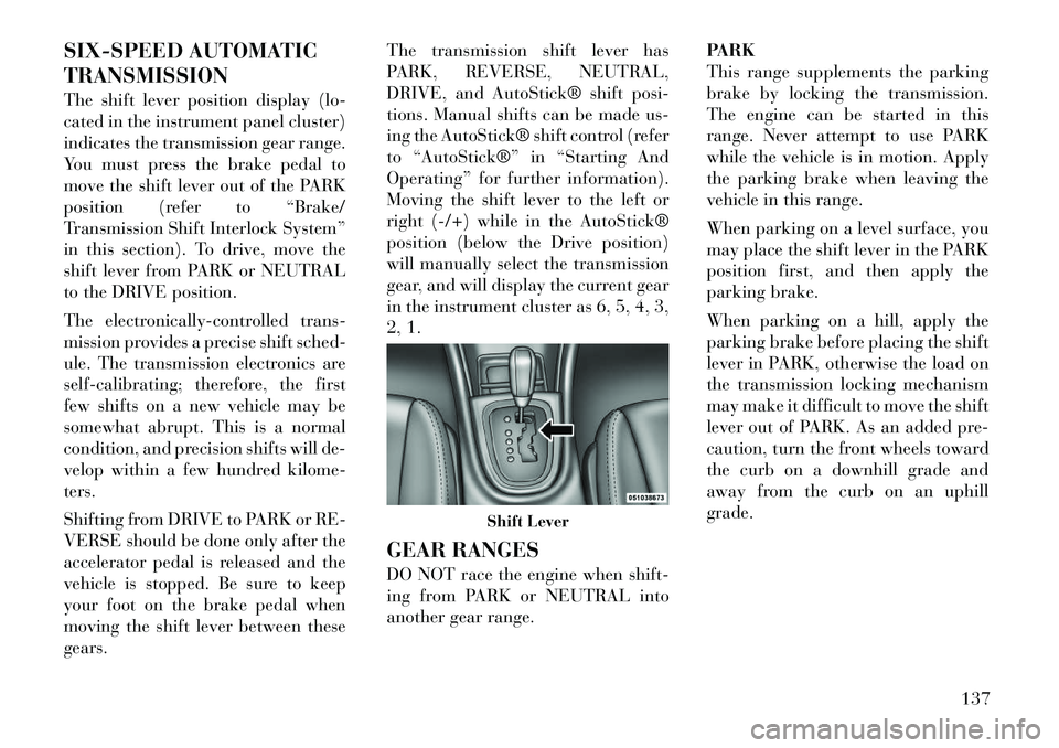
gears.The transmission shift lever has
PARK, REVERSE, NEUTRAL,
DRIVE, and AutoStick® shift posi-
tions. Manual shifts can be made us-
ing the AutoStick® shift control (refer
to “AutoStick®” in “Starting And
Operating” for further information).
Moving the shift lever to the left or
right (-/+) while in the AutoStick®
position (below the Drive position)
will manually select the transmission
gear, and will display the current gear
in the instrument cluster as 6, 5, 4, 3,
2, 1.
GEAR RANGES
DO NOT race the engine when shift-
ing from PARK or NEUTRAL into
another gear range.
PARK
This range supplements the parking
brake by locking the transmission.
The engine can be started in this
range. Never attempt to use PARK
while the vehicle is in motion. Apply
the parking brake when leaving the
vehicle in this range.
When parking on a level surface, you
may place the shift lever in the PARK
position first, and then apply the
parking brake.
When parking on a hill, apply the
parking brake before placing the shift
lever in PARK, otherwise the load on
the transmission locking mechanism
may make it difficult to move the shift
lever out of PARK. As an added pre-
caution, turn the front wheels toward
the curb on a downhill grade and
away from the curb on an uphill
grade.
Shift Lever
137
Page 148 of 233

Torque Converter Clutch
A feature designed to improve fuel
economy has been included in the au-
tomatic transmission on your vehicle.
A clutch within the torque converter
engages automatically at calibrated
speeds. This may result in a slightly
different feeling or response during
normal operation in the upper gears.
When the vehicle speed drops or dur-
ing some accelerations, the clutch au-
tomatically disengages.
NOTE:
The torque converter clutch will
not engage until the transmission
fluid and engine coolant are warm
[usually after 2 to 5 km of driving].
Because the engine speed is higher
when the torque converter clutch
is not engaged, it may seem as if the
transmission is not shifting into
Overdrive when cold. This is nor-
mal. Using the AutoStick® feature,
when the transmission is suffi-
ciently warm, will demonstrate
that the transmission is able to
shift into and out of Overdrive.AUTOSTICK®
AutoStick® is a driver-interactive
feature providing manual shift con-
trol, giving you more control of the
vehicle. AutoStick® allows you to
maximize engine braking, eliminate
undesirable upshifts and downshifts,
and improve overall vehicle perfor-
mance. This system can also provide
you with more control during passing,
city driving, cold slippery conditions,
mountain driving, and many other
situations.
OPERATION
When the shift lever is in the
AutoStick® position (below the
DRIVE position), it can be moved
from side to side. This allows the
driver to manually select the trans-
mission gear being used. Moving the
shift lever to the left (-) triggers a
downshift and to the right (+) an up-
shift. The gear position will display in
the instrument cluster on the trans-
mission range indicator.
NOTE:
In AutoStick® mode, the transmis-
sion will only shift up or down
when the driver moves the shift
lever to the right (+) or left (-), or as
described below.
AutoStick® is deactivated when the
shift lever is moved from the
AutoStick (+/-) position into the
DRIVE position.
GENERAL INFORMATION
You can start out, from a stop, in
any gear except sixth. The system
will ignore attempts to upshift at
too low of a vehicle speed.
If a ratio other than first gear is selected, and the vehicle is brought
to a stop, the transmission control
logic will automatically select the
first gear ratio.
Starting out in second gear is help- ful in snowy or icy conditions. To
select second gear after the vehicle
is brought to a stop, tap the shift
lever to the right (+) once.
Avoid using speed control when AutoStick® is engaged.
141
Page 164 of 233

NOTE:
The TPMS is not intended to re-
place normal tire care and main-
tenance, or to provide warning of
a tire failure or condition. The TPMS should not be used asa tire pressure gauge while ad-
justing your tire pressure.
Driving on a significantly under-
inflated tire causes the tire to
overheat and can lead to tire fail-
ure. Under-inflation also reduces
fuel efficiency and tire tread life,
and may affect the vehicle’s han-
dling and stopping ability.The TPMS is not a substitute for
proper tire maintenance, and it is
the driver’s responsibility to
maintain correct tire pressure us-
ing an accurate tire pressure
gauge, even if under-inflation has
not reached the level to trigger
illumination of the “Tire Pres-
sure Monitoring Telltale Light.” Seasonal temperature changes will affect tire pressure, and the
TPMS will monitor the actual
tire pressure in the tire. PREMIUM SYSTEM
The Tire Pressure Monitor System
(TPMS) uses wireless technology with
wheel rim mounted electronic sensors
to monitor tire pressure levels. Sen-
sors, mounted to each wheel as part of
the valve stem, transmit tire pressure
readings to the Receiver Module.
NOTE:
It is particularly important for you
to check the tire pressure in all of
the tires on your vehicle monthly
and to maintain the proper pres-
sure.
The TPMS consists of the following
components:
Receiver Module
Four Tire Pressure Monitoring Sen-
sors
Three Trigger Modules (mounted in three of the four wheel-wells)
Various Tire Pressure Monitoring System Messages, which display in
the Electronic Vehicle Information
Center (EVIC)
Tire Pressure Monitoring Telltale Light Tire Pressure Monitoring Low
Pressure Warnings
The “Tire Pressure Monitoring
Telltale Light” will illuminate
in the instrument cluster and a
chime will sound when tire pressure is
low in one or more of the four active
road tires. In addition, the Electronic
Vehicle Information Center (EVIC)
will display a graphic showing the
pressure values of each tire with the
low tire pressure values flashing.
Should this occur, you should stop as
soon as possible, and inflate all tires
with low pressure (those flashing in
the EVIC graphic) to the vehicle’s rec-
ommended cold placard pressure
value. Once the system receives the
updated tire pressures, the system will
automatically update, the graphic
display in the EVIC will stop flashing,
and the “Tire Pressure Monitoring
Telltale Light” will turn off. The ve-
hicle may need to be driven for up to
20 minutes above 24 km/h in order
for the TPMS to receive this informa-
tion.
157
Page 165 of 233

Check TPMS Warning
When a system fault is detected, a
chime will sound and the “Tire Pres-
sure Monitoring Telltale Light” will
flash on and off for 75 seconds and
then remain on solid. In addition, the
EVIC will display a "CHECK TPM
SYSTEM" message for a minimum of
five seconds and then display dashes
(- -) in place of the pressure value to
indicate which sensor is not being re-
ceived.
If the ignition key is cycled, this se-
quence will repeat, providing the sys-
tem fault still exists. If the system
fault no longer exists, the “Tire Pres-
sure Monitoring Telltale Light” will
no longer flash, and the "CHECK
TPM SYSTEM" message will no lon-
ger display, and a pressure value will
display in place of the dashes. A sys-
tem fault can occur due to any of the
following:
1. Jamming due to electronic devices
or driving next to facilities emitting
the same Radio Frequencies as the
TPM sensors.2. Installing some form of aftermar-
ket window tinting that affects radio
wave signals.
3. Lots of snow or ice around the
wheels or wheel housings.
4. Using tire chains on the vehicle.
5. Using wheels/tires not equipped
with TPM sensors.
The EVIC will also display a
"CHECK TPM SYSTEM" message
for a minimum of five seconds when a
system fault related to an incorrect
sensor location fault is detected. In
this case, the "CHECK TPM SYS-
TEM" message is then followed with a
graphic display with pressure values
still shown. This indicates that the
pressure values are still being received
from the TPM sensors but they may
not be located in the correct vehicle
position. The system still needs to be
serviced as long as the "CHECK TPM
SYSTEM" message is displayed.
FUEL REQUIREMENTS
All engines are designed to meet all
emissions regulations and provide ex-
cellent fuel economy and performance
when using high quality unleaded
gasoline with a minimum research oc-
tane rating of 91.
Light spark knock at low engine speeds
is not harmful to your engine. How-
ever, continued heavy spark knock at
high speeds can cause damage and im-
mediate service is required. Poor qual-
ity gasoline can cause problems such as
hard starting, stalling, and hesitations.
If you experience these symptoms, try
another brand of gasoline before con-
sidering service for the vehicle.Over 40 auto manufactur
er's world
wide have issued and endorsed con-
sistent gasoline specifications (the
Worldwide Fuel Charter, WWFC)
which define fuel properties necessary
to deliver enhanced emissions, perfor-
mance, and durability for your ve-
hicle. The manufacturer recommends
the use of gasoline that meets the
WWFC specifications if they are
available.
158
Page 168 of 233

NOTE:
If the gas cap is lost or damaged, be
sure the replacement cap is for use
with this vehicle.CAUTION!
Damage to the fuel system oremission control system could r e-
sult from using an improper fuel
tank filler tube cap (gas cap).
A poorly fitting gas cap may cause
the “Malfunction Indicator Light
(MIL)” to turn on.
To avoid fuel spillage and overfill-
ing, do not “top off” the fuel tank
after filling. When the fuel nozzle
“clicks” or shuts off, the fuel tank
is full.WARNING!
Never have any smoking materi-als lit in or near the vehicle when
the gas cap is removed or the tank
is being filled.
(Continued)
WARNING!(Continued)
A fire may result if gasoline is
pumped into a portable container
that is inside of a vehicle. You
could be burned. Always place gas
containers on the ground while
filling.
NOTE:
Tighten the gas cap until you hear a “clicking” sound. This is
an indication that the gas cap is
tightened properly. The MIL in
the instrument cluster may turn
on if the gas cap is not secured
properly. Make sure that the gas
cap is tightened each time the
vehicle is refueled.
When the fuel nozzle “clicks” or shuts off, the fuel tank is full.
LOOSE FUEL FILLER CAP
MESSAGE
If the vehicle diagnostic system deter-
mines that the fuel filler cap is loose,
improperly installed, or damaged, a
“CHECK GAS CAP” message will be
displayed in the EVIC (Electronic Ve-
hicle Information Center). Refer to “Electronic Vehicle Information Cen-
ter” in “Understanding Your Instru-
ment Panel” for further information.
Tighten the fuel filler cap properly
and press the odometer reset button to
turn the message off. If the problem
continues, the message will appear
the next time the vehicle is started.
Refer to “Onboard Diagnostic Sys-
tem” in “Maintaining Your Vehicle”
for further information.
NOTE:
If the gas cap is lost or damaged, be
sure the replacement cap is for use
with this vehicle.
VEHICLE LOADING
VEHICLE CERTIFICATION
LABEL
Your vehicle has a certification label
attached to the rear of the
driver's
door.
The label contains the following infor -
mation:
Name of manufacturer
Month and year of manufacture
161
Page 219 of 233

MAINTENANCE
SCHEDULE
The Scheduled Maintenance services
listed in this manual must be done at
the times or mileages specified to pro-
tect your vehicle warranty and ensure
the best vehicle performance and reli-
ability. More frequent maintenance
may be needed for vehicles in severe
operating conditions, such as dusty
areas and very short trip driving. In-
spection and service should also be
done anytime a malfunction is sus-
pected.
The oil change indicator system will
remind you that it is time to take your
vehicle in for scheduled maintenance.On Electronic Vehicle Information
Center (EVIC) equipped vehicles “Oil
Change Required” will be displayed
in the EVIC and a single chime will
sound, indicating that an oil change is
necessary.
NOTE:
The oil change indicator mes-
sage will not monitor the time
since the last oil change. Change
your vehicles oil if it has been
12 months since your last oil
change even if the oil change in-
dicator message is NOT illumi-
nated. Under no circumstances should
oil change intervals exceed
12 000 km or 12 months, which-
ever comes first.
Your authorized dealer will reset the
oil change indicator message after
completing the scheduled oil change.
CAUTION!
Failure to perform the required
maintenance items may result in
damage to the vehicle.
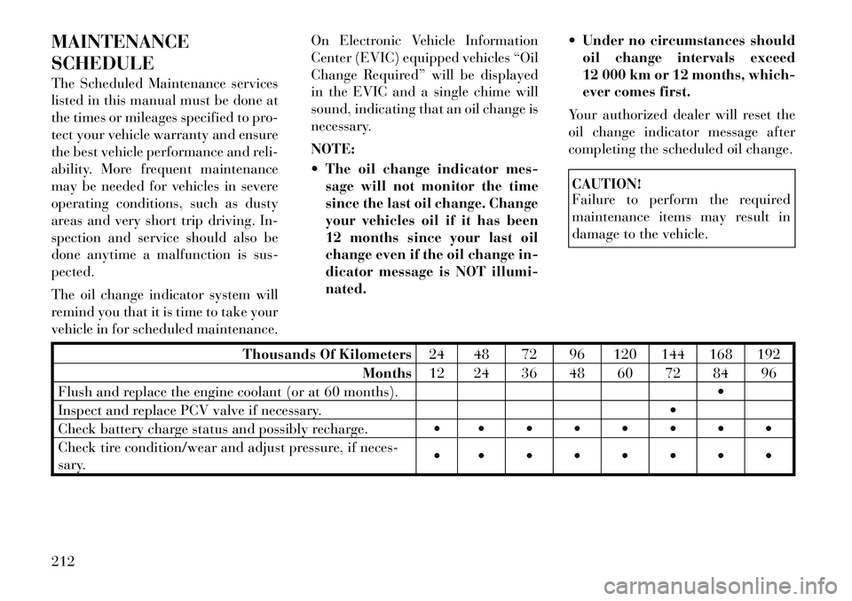
Thousands Of Kilometers 24 48 72 96 120 144 168 192
Months 12 24 36 48 60 72 84 96
Flush and replace the engine coolant (or at 60 months).
Inspect and replace PCV valve if necessary.
Check battery charge status and possibly recharge.
Check tire condition/wear and adjust pressure, if neces-
sary.
212