turn signal bulb Lancia Flavia 2012 Owner handbook (in English)
[x] Cancel search | Manufacturer: LANCIA, Model Year: 2012, Model line: Flavia, Model: Lancia Flavia 2012Pages: 233, PDF Size: 2.61 MB
Page 20 of 233
WARNING!(Continued)
Allowing children to be in a ve-
hicle unattended is dangerous for
a number of reasons. A child or
others could be seriously or fatally
injured. Children should be
warned not to touch the parking
brake, brake pedal or the shift
lever.
Do not leave the key fob in or near
the vehicle, and do not leave the
ignition in the ACC or ON/RUN
position. A child could operate
power windows, other controls, or
move the vehicle.CAUTION!
An unlocked car is an invitation to
thieves. Always remove key from the
ignition and lock all doors when
leaving the vehicle unattended.
KEY-IN-IGNITION
REMINDER
Opening the driver's door when the
key is in the ignition sounds a signal to
remind you to remove the key. NOTE:
The Key-In-Ignition reminder
only sounds when the ignition
key is placed in the LOCK or
ACC position.
With either/both front doors open and a key in the ignition,
the power door lock buttons on
the interior trim panel are dis-
abled. This is an attempt to limit
locking the keys in the vehicle.
LOCKING THE DOORS
WITH THE KEY
There is only one external door lock
cylinder which is located in the driv-
er's door.
You can insert the key with either side
up. To lock the door, turn the key
clockwise. To unlock the door, turn
the key counterclockwise. For door
lock lubrication, see “Maintenance
Procedures” in “Maintaining Your Ve-
hicle” of this manual.
SENTRY KEY®
The Sentry Key® Immobilizer System
prevents unauthorized vehicle opera-
tion by disabling the engine. The sys- tem does not need to be armed or
activated. Operation is automatic, re-
gardless of whether the vehicle is
locked or unlocked.
The system uses ignition keys which
have an embedded electronic chip
(transponder) to prevent unauthor-
ized vehicle operation. Therefore,
only keys that are programmed to the
vehicle can be used to start and oper-
ate the vehicle. The system will shut
the engine off in two seconds if some-
one uses an invalid key to start the
engine.
NOTE:
A key which has not been pro-
grammed is also considered an in-
valid key, even if it is cut to fit the
ignition switch lock cylinder for
that vehicle.
During normal operation, after turn-
ing on the ignition switch, the Vehicle
Security Light will turn on for three
seconds for a bulb check. If the light
remains on after the bulb check, it
indicates that there is a problem with
the electronics. In addition, if the light
begins to flash after the bulb check, it
13
Page 40 of 233
check, the Air Bag Warning Light will
turn off. If the ORC detects a mal-
function in any part of the system, it
turns on the Air Bag Warning Light,
either momentarily or continuously. A
single chime will sound if the light
comes on again after initial startup.
It also includes diagnostics that will
illuminate the instrument cluster Air
Bag Warning Light if a malfunction is
noted that could affect the air bag
system. The diagnostics also record
the nature of the malfunction.WARNING!
Ignoring the Air Bag Warning Light
in your instrument panel could
mean you won't have the air bags to
protect you in a collision. If the light
does not come on as a bulb check
when the ignition is first turned on,
stays on after you start the vehicle,
or if it comes on as you drive, have
an authorized dealer service the air
bag system immediately.Driver And Passenger Advanced
Front Air Bag Inflator Units
The Driver and Passenger Advanced
Front Air Bag Inflator Units are lo-
cated in the center of the steering
wheel and on the right side of the
instrument panel. When the ORC de-
tects a collision requiring the Ad-
vanced Front Air Bags, it signals the
inflator units. A large quantity of non-
toxic gas is generated to inflate the
Advanced Front Air Bags. Different
air bag inflation rates are possible,
based on the collision type and sever-
ity. The steering wheel hub trim cover
and the upper right side of the instru-
ment panel separate and fold out of
the way as the air bags inflate to their
full size. The air bags fully inflate in
about 50 to 70 milliseconds. This is
about half of the time it takes to blink
your eyes. The air bags then quickly
deflate while helping to restrain the
driver and front passenger.
The Advanced Front Air Bag gas is
vented through the vent holes in the
sides of the air bag. In this way, the air
bags do not interfere with your con-
trol of the vehicle. Supplemental Seat-Mounted Side
Air Bag (SAB) Inflator Units
The Supplemental Seat-Mounted
Side Air Bags (SAB) are designed to
activate only in certain side collisions.
The ORC determines if a side collision
requires the side air bags to inflate,
based on several factors, including the
severity and type of collision.
Based on several factors, including
the severity and type of collision, the
side air bag inflator on the crash side
of the vehicle may be triggered, re-
leasing a quantity of non-toxic gas.
The inflating SAB exits through the
seat seam into the space between the
occupant and the door. The SAB fully
inflate in about 10 milliseconds. The
side air bag moves at a very high
speed and with such a high force that
it could injure you if you are not
seated properly, or if items are posi-
tioned in the area where the side air
bag inflates. This especially applies to
children.
33
Page 118 of 233
15. Cruise IndicatorThis indicator shows that
the Electronic Speed Con-
trol System is ON.
16. Odometer/Trip Odometer Reset
Button
Trip Odometer
Press and release this button to
change the display from odometer to
“Trip A.” Press and release it a second
time to change the display to “Trip
B.” Press and release it a third time to
change the display back to the odom-
eter.
To reset the trip odometer, first dis-
play the trip mileage that you want to
reset, “Trip A” or “Trip B.” Then push
and hold the button (approximately
2 seconds) until the display resets to
0 miles (km). The odometer must be
in Trip Mode to reset the trip odom-
eter. 17. Electronic Throttle Control
(ETC) Indicator Light
This light informs you of a
problem with the Electronic
Throttle Control (ETC)
system. If a problem is de-
tected, the light will come on while the
engine is running. If the light remains
lit with the engine running, your ve-
hicle will usually be drivable and not
need towing, however see your autho-
rized dealer for service as soon as pos-
sible.
If the light is flashing when the engine
is running you may experience power
loss, an elevated/rough idle, and in-
creased brake pedal effort, and your
vehicle may require towing. Immedi-
ate service is required.
The light will come on when the igni-
tion switch is first turned on and re-
main on approximately 15 seconds as
a bulb check. This is normal. If the
light does not come on during start-
ing, have the system checked by an
authorized dealer. 18. Park/Headlight ON Indicator
This indicator will illumi-
nate when the park lights or
headlights are turned on.
19. Electronic Stability Control
(ESC) OFF Indicator Light This light indicates the
Electronic Stability Control
system (ESC) has been
turned off by the driver.
20. Turn Signal Indicators The arrows will flash in uni-
son with the exterior turn
signal, when using the turn
signal lever. A chime will
sound if the vehicle is driven more
than 1.6 km with either turn signal
on.
NOTE:
If either indicator flashes at a
rapid rate, check for a defective
outside light bulb.
111
Page 120 of 233
bel. (If your vehicle has tires of a
different size than the size indicated
on the vehicle placard or tire inflation
pressure label, you should determine
the proper tire inflation pressure for
those tires.)
As an added safety feature, your ve-
hicle has been equipped with a Tire
Pressure Monitoring System (TPMS)
that illuminates a low tire pressure
telltale when one or more of your tires
is significantly under-inflated. Ac-
cordingly, when the low tire pressure
telltale illuminates, you should stop
and check your tires as soon as pos-
sible, and inflate them to the proper
pressure. Driving on a significantly
under-inflated tire causes the tire to
overheat and can lead to tire failure.
Under-inflation also reduces fuel effi-
ciency and tire tread life, and may
affect the vehicle’s handling and stop-
ping ability.Please note that the TPMS is not a
substitute for proper tire maintenance,
and it is the driver’s responsibility to
maintain correct tire pressure, even if
under-inflation has not reached thelevel to trigger illumination of the
TPMS low tire pressure telltale.
Your vehicle has also been equipped
with a TPMS malfunction indicator to
indicate when the system is not oper-
ating properly. The TPMS malfunc-
tion indicator is combined with the
low tire pressure telltale. When the
system detects a malfunction, the tell-
tale will flash for approximately one
minute and then remain continuously
illuminated. This sequence will con-
tinue upon subsequent vehicle start-
ups as long as the malfunction exists.
When the malfunction indicator is il-
luminated, the system may not be
able to detect or signal low tire pres-
sure as intended. TPMS malfunctions
may occur for a variety of reasons,
including the installation of replace-
ment or alternate tires or wheels on
the vehicle that prevent the TPMS
from functioning properly. Always
check the TPMS malfunction telltale
after replacing one or more tires or
wheels on your vehicle, to ensure that
the replacement or alternate tires and
wheels allow the TPMS to continue to
function properly.
CAUTION!
The TPMS has been optimized for
the original equipment tires and
wheels. TPMS pressures and warn-
ing have been established for the tire
size equipped on your vehicle. Un-
desirable system operation or sensor
damage may result when using re-
placement equipment that is not of
the same size, type, and/or style.
Aftermarket wheels can cause sensor
damage. Do not use tire sealant from
a can or balance beads if your ve-
hicle is equipped with a TPMS, as
damage to the sensors may result.
26. Malfunction Indicator Light
(MIL) The Malfunction Indicator
Light (MIL) is part of an on-
board diagnostic system
called OBD that monitors
emissions, engine, and automatic
transmission control systems. The
light will illuminate when the key is in
the ON/RUN position before engine
start. If the bulb does not come on
when turning the key from LOCK to
ON/RUN, have the condition checked
promptly.
113
Page 187 of 233

CONVERTIBLE TOP CARE . . . . . . . . . . . . . . 198
WEATHER STRIP CARE – SOFT AND HARDTOP . . . . . . . . . . . . . . . . . . . . . . . . . . . . . . . . 200
FUSES . . . . . . . . . . . . . . . . . . . . . . . . . . . . . . . . 200 INTEGRATED POWER MODULE . . . . . . . . . . 200
VEHICLE STORAGE . . . . . . . . . . . . . . . . . . . . . 203
REPLACEMENT BULBS . . . . . . . . . . . . . . . . . . 203
BULB REPLACEMENT . . . . . . . . . . . . . . . . . . . 203 HEADLAMP . . . . . . . . . . . . . . . . . . . . . . . . . . 203
FRONT TURN SIGNAL . . . . . . . . . . . . . . . . . . 204
FRONT FOG LAMP . . . . . . . . . . . . . . . . . . . . 204
REAR TURN SIGNAL LAMPS . . . . . . . . . . . . 205
BACKUP LAMP . . . . . . . . . . . . . . . . . . . . . . . 205
LICENSE PLATE LAMP . . . . . . . . . . . . . . . . . 205
FLUID CAPACITIES . . . . . . . . . . . . . . . . . . . . . . 206
FLUIDS, LUBRICANTS, AND GENUINE PARTS . . . . . . . . . . . . . . . . . . . . . . . . . . . . . . . . 206
ENGINE . . . . . . . . . . . . . . . . . . . . . . . . . . . . . 206
CHASSIS . . . . . . . . . . . . . . . . . . . . . . . . . . . . 207
180
Page 210 of 233
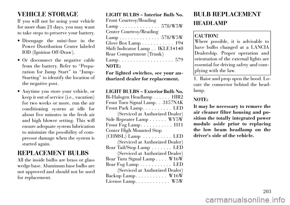
VEHICLE STORAGE
If you will not be using your vehicle
for more than 21 days, you may want
to take steps to preserve your battery.
Disengage the mini-fuse in thePower Distribution Center labeled
IOD (Ignition Off-Draw).
Or disconnect the negative cable from the battery. Refer to “Prepa-
ration for Jump Start” in “Jump-
Starting” to identify the location of
the negative post.
Anytime you store your vehicle, or keep it out of service (i.e., vacation)
for two weeks or more, run the air
conditioning system at idle for
about five minutes in the fresh air
and high blower setting. This will
ensure adequate system lubrication
to minimize the possibility of com-
pressor damage when the system is
started again.
REPLACEMENT BULBS
All the inside bulbs are brass or glass
wedge base. Aluminum base bulbs are
not approved and should not be used
for replacement. LIGHT BULBS – Interior Bulb No.
Front Courtesy/Reading
Lamp . . . . . . . . . . . . . . 578/W5W
Center Courtesy/Reading
Lamp . . . . . . . . . . . . . . 578/W5W
Glove Box Lamp . . . . . . . . . . . 194
Shift Indicator Lamp . . IKLE14140
Rear Compartment (Trunk)
Lamp . . . . . . . . . . . . . . . . . . . 579
NOTE:
For lighted switches, see your au-
thorized dealer for replacement.
LIGHT BULBS – Exterior Bulb No.
Bi-Halogen Headlamp . . . . . . HIR2
Front Turn Signal Lamp . . 3157NAKFront Park Lamp . . . . . . . . . . LED
(Serviced at Authorized Dealer)
Side Repeater Lamp . . . . . . WY5W
Front Fog Lamp . . . . . . . . . . . H11
Center High Mounted Stop
(CHMSL) Lamp . . . . . . . . . . LED
(Serviced at Authorized Dealer)
Rear Tail/Stop Lamp . . . . . . . LED
(Serviced at Authorized Dealer)
Rear Turn Signal Lamp . . . . W16W
Rear Fog Lamp . . . . . . . . . . . LED
(Serviced at Authorized Dealer)
Backup Lamp . . . . . . . . . . . W16W
License Lamp. . . . . . . . . . . . W5W BULB REPLACEMENT
HEADLAMP
CAUTION!
Where possible, it is advisable to
have bulbs changed at a LANCIA
Dealership. Proper operation and
orientation of the external lights are
essential for driving safety and com-
plying with the law.
1. Raise and prop open the hood. Lo-
cate the connector behind the head-
lamp.
NOTE:
It may be necessary to remove the
air cleaner filter housing and po-
sition the totally integrated power
module aside prior to replacing
the low beam headlamp on the
driver's side of the vehicle.
203
Page 211 of 233

2. Reach into engine compartment
and from behind the lamp assembly
and grasp the connector.
3. Rotate bulb and connector one-
quarter turn and pull outward from
assembly.CAUTION!
Do not touch the new bulb with your
fingers. Oil contamination will se-
verely shorten bulb life.
4. Pull the bulb out of the socket and
replace the bulb. 5. If the bulb comes in contact with
any oily surface, clean the bulb with
rubbing alcohol.
6. Reinsert the bulb and socket as-
sembly and rotate clockwise one-
quarter turn to secure.
FRONT TURN SIGNAL
1. Raise and prop open the hood.
2. Rotate the
bulb's electrical con-
nector one-quarter turn counter-
clockwise and remove it from the
headlamp housing.
3. Remove the bulb from the connec-
tor socket and install the replacement
bulb.
4. Install the bulb and connector as-
sembly into the headlamp housing
and rotate the connector one-quarter
turn clockwise to lock it in place. FRONT FOG LAMP
NOTE:
Access to the lamps through the
lower fascia cutout is limited. We
recommend you access the lamps
by turning the steering wheel to
allow access and remove the inner
fender shield.
1. Rotate the
bulb's electrical con-
nector one-quarter turn counter-
clockwise and remove it from the fog
lamp housing.
2. Remove the bulb from the connec-
tor socket and install the replacement
bulb.
CAUTION!
Do not touch the new bulb with your
fingers. Oil contamination will se-
verely shorten bulb life. If the bulb
comes in contact with an oily sur-
face, clean the bulb with rubbing
alcohol.
3. Install the bulb and connector as-
sembly into the fog lamp housing and
rotate the connector one-quarter turn
clockwise to lock it in place.
204
Page 212 of 233

REAR TURN SIGNAL
LAMPS
1. Open the trunk and gently pull
back the trunk liner behind the tail
lamp (requires removal of a push pin
holding the trunk trim in place near
the tail lamp).
2. Remove the two plastic wing nuts
from the tail lamp housing.
NOTE:
Placing a small flat head screw-
driver or similar tool between the
lamp outboard ball stud and plas-
tic grommet from inside the trunk
can help to disengage the outboard
edge of the tail lamp.
3. Grasp the tail lamp by both the
outboard and inboard sides, and pull
firmly to disengage the tail lamp from
the vehicle.NOTE:
It is normal to hear a loud sound
when the lower tail lamp area un-
snaps from the vehicle mounting
bracket during tail lamp removal.
4. Twist and remove socket from
lamp.
5. Remove bulb from socket and re-
place.
6. Reinstall the tail lamp, fasteners,
and trunk liner.
BACKUP LAMP
1. Remove four push pins from the
bottom of the lower valance (from left
to right: 1st, 3rd, 6th & 8th) and two
push pins from the rear of the bracket.
2. Remove bracket by pulling for-
ward of vehicle.
3. Remove socket from housing with
a counter-clockwise
1�4turn.
4. Remove bulb from socket by pull-
ing directly out (do not turn/twist)
and install replacement bulb.
5. Insert socket back into the housing
with a clockwise
1�4turn.
6. Return bracket into position.
7. Snap the six (6) push pins back
into place.
LICENSE PLATE LAMP
1. Using a small screwdriver, press
inward the locking tab on the side of
the lamp assembly and pull down on
the lamp assembly for removal.
2. Remove bulb socket by twisting
out of lamp assembly.
3. Pull bulb from socket, replace, and
reinstall the bulb socket into lamp
assembly.
4. Install lamp assembly to lightbar
ensuring the locking tab is secure.
205
Page 226 of 233
Gas Cap (Fuel Filler Cap) . . . . 160
Gasoline (Fuel) . . . . . . . . . . . 158
Gasoline, Clean Air . . . . . . . . 159
GaugesCoolant Temperature . . . . . 107
Fuel . . . . . . . . . . . . . . . . . 107
Odometer . . . . . . . . . . . . . 109
Tachometer . . . . . . . . . . . . 109
Gear Ranges . . . . . . . . . . . . . 137
Gear Select Lever Override . . . 175
General Information . . . . . . . . 14
General Maintenance . . . . . . . 182
Glass Cleaning . . . . . . . . . . . . 197
Gross Axle Weight Rating . . . . 162
Gross Vehicle Weight Rating . . 162
GVWR . . . . . . . . . . . . . . . . . 162
Hands-Free Phone
(Uconnect™) . . . . . . . . . . . . . 65
Hazard Driving Through Flowing,
Rising, or Shallow Standing
Water . . . . . . . . . . . . . . . . 142
Hazard Warning Flasher . . . . . 166
Head Restraints . . . . . . . . . . . . 88
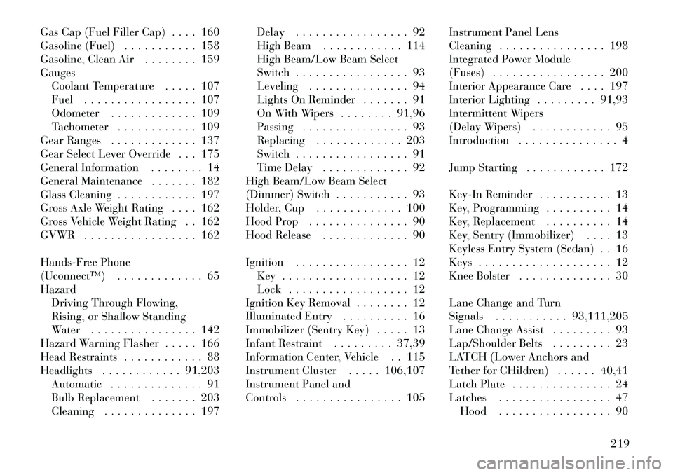
Headlights . . . . . . . . . . . . 91,203 Automatic . . . . . . . . . . . . . . 91
Bulb Replacement . . . . . . . 203
Cleaning . . . . . . . . . . . . . . 197 Delay . . . . . . . . . . . . . . . . . 92
High Beam . . . . . . . . . . . . 114
High Beam/Low Beam Select
Switch . . . . . . . . . . . . . . . . . 93
Leveling . . . . . . . . . . . . . . . 94
Lights On Reminder . . . . . . . 91
On With Wipers . . . . . . . . 91,96
Passing . . . . . . . . . . . . . . . . 93
Replacing . . . . . . . . . . . . . 203
Switch . . . . . . . . . . . . . . . . . 91
Time Delay . . . . . . . . . . . . . 92
High Beam/Low Beam Select
(Dimmer) Switch . . . . . . . . . . . 93
Holder, Cup . . . . . . . . . . . . . 100
Hood Prop . . . . . . . . . . . . . . . 90
Hood Release . . . . . . . . . . . . . 90
Ignition . . . . . . . . . . . . . . . . . 12 Key . . . . . . . . . . . . . . . . . . . 12
Lock . . . . . . . . . . . . . . . . . . 12
Ignition Key Removal . . . . . . . . 12
Illuminated Entry . . . . . . . . . . 16
Immobilizer (Sentry Key) . . . . . 13
Infant Restraint . . . . . . . . . 37,39
Information Center, Vehicle . . 115
Instrument Cluster . . . . . 106,107
Instrument Panel and
Controls . . . . . . . . . . . . . . . . 105 Instrument Panel Lens
Cleaning . . . . . . . . . . . . . . . . 198
Integrated Power Module
(Fuses) . . . . . . . . . . . . . . . . . 200
Interior Appearance Care . . . . 197
Interior Lighting . . . . . . . . . 91,93
Intermittent Wipers
(Delay Wipers) . . . . . . . . . . . . 95
Introduction . . . . . . . . . . . . . . . 4
Jump Starting . . . . . . . . . . . . 172
Key-In Reminder . . . . . . . . . . . 13
Key, Programming . . . . . . . . . . 14
Key, Replacement . . . . . . . . . . 14
Key, Sentry (Immobilizer) . . . . 13
Keyless Entry System (Sedan) . . 16
Keys . . . . . . . . . . . . . . . . . . . . 12
Knee Bolster . . . . . . . . . . . . . . 30
Lane Change and Turn
Signals . . . . . . . . . . . 93,111,205
Lane Change Assist . . . . . . . . . 93
Lap/Shoulder Belts . . . . . . . . . 23
LATCH (Lower Anchors and
Tether for CHildren) . . . . . . 40,41
Latch Plate . . . . . . . . . . . . . . . 24
Latches . . . . . . . . . . . . . . . . . 47
Hood . . . . . . . . . . . . . . . . . 90
219
Page 227 of 233
Lead Free Gasoline . . . . . . . . 158
Leaks, Fluid . . . . . . . . . . . . . . 47
Leveling, Headlight . . . . . . . . . 94
Life of Tires . . . . . . . . . . . . . 153
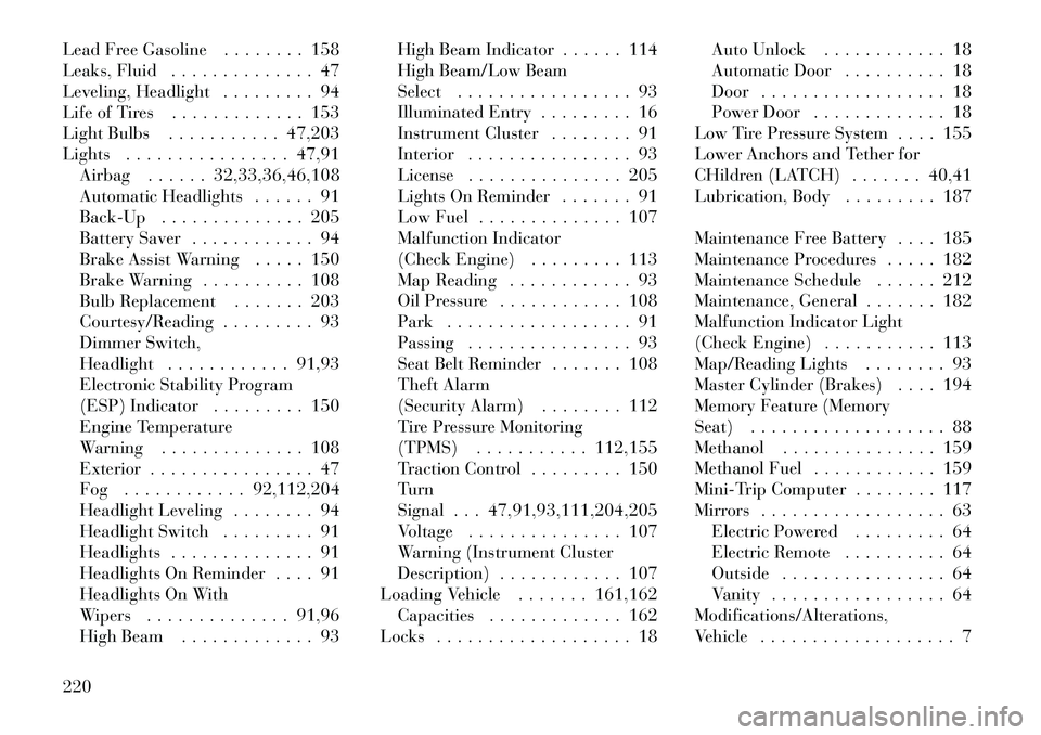
Light Bulbs . . . . . . . . . . . 47,203
Lights . . . . . . . . . . . . . . . . 47,91Airbag . . . . . . 32,33,36,46,108
Automatic Headlights . . . . . . 91
Back-Up . . . . . . . . . . . . . . 205
Battery Saver . . . . . . . . . . . . 94
Brake Assist Warning . . . . . 150
Brake Warning . . . . . . . . . . 108
Bulb Replacement . . . . . . . 203
Courtesy/Reading . . . . . . . . . 93
Dimmer Switch,
Headlight . . . . . . . . . . . . 91,93
Electronic Stability Program
(ESP) Indicator . . . . . . . . . 150
Engine Temperature
Warning . . . . . . . . . . . . . . 108
Exterior . . . . . . . . . . . . . . . . 47
Fog . . . . . . . . . . . . 92,112,204
Headlight Leveling . . . . . . . . 94
Headlight Switch . . . . . . . . . 91
Headlights . . . . . . . . . . . . . . 91
Headlights On Reminder . . . . 91
Headlights On With
Wipers . . . . . . . . . . . . . . 91,96
High Beam . . . . . . . . . . . . . 93 High Beam Indicator . . . . . . 114
High Beam/Low Beam
Select . . . . . . . . . . . . . . . . . 93
Illuminated Entry . . . . . . . . . 16
Instrument Cluster . . . . . . . . 91
Interior . . . . . . . . . . . . . . . . 93
License . . . . . . . . . . . . . . . 205
Lights On Reminder . . . . . . . 91
Low Fuel . . . . . . . . . . . . . . 107
Malfunction Indicator
(Check Engine) . . . . . . . . . 113
Map Reading . . . . . . . . . . . . 93
Oil Pressure . . . . . . . . . . . . 108
Park . . . . . . . . . . . . . . . . . . 91
Passing . . . . . . . . . . . . . . . . 93
Seat Belt Reminder . . . . . . . 108
Theft Alarm
(Security Alarm) . . . . . . . . 112
Tire Pressure Monitoring
(TPMS) . . . . . . . . . . . 112,155
Traction Control . . . . . . . . . 150
Turn
Signal . . . 47,91,93,111,204,205
Voltage . . . . . . . . . . . . . . . 107
Warning (Instrument Cluster
Description) . . . . . . . . . . . . 107
Loading Vehicle . . . . . . . 161,162 Capacities . . . . . . . . . . . . . 162
Locks . . . . . . . . . . . . . . . . . . . 18 Auto Unlock . . . . . . . . . . . . 18
Automatic Door . . . . . . . . . . 18
Door . . . . . . . . . . . . . . . . . . 18
Power Door . . . . . . . . . . . . . 18
Low Tire Pressure System . . . . 155
Lower Anchors and Tether for
CHildren (LATCH) . . . . . . . 40,41
Lubrication, Body . . . . . . . . . 187
Maintenance Free Battery . . . . 185
Maintenance Procedures . . . . . 182
Maintenance Schedule . . . . . . 212
Maintenance, General . . . . . . . 182
Malfunction Indicator Light
(Check Engine) . . . . . . . . . . . 113
Map/Reading Lights . . . . . . . . 93
Master Cylinder (Brakes) . . . . 194
Memory Feature (Memory
Seat) . . . . . . . . . . . . . . . . . . . 88
Methanol . . . . . . . . . . . . . . . 159
Methanol Fuel . . . . . . . . . . . . 159
Mini-Trip Computer . . . . . . . . 117
Mirrors . . . . . . . . . . . . . . . . . . 63 Electric Powered . . . . . . . . . 64
Electric Remote . . . . . . . . . . 64
Outside . . . . . . . . . . . . . . . . 64
Vanity . . . . . . . . . . . . . . . . . 64
Modifications/Alterations,
Vehicle . . . . . . . . . . . . . . . . . . . 7
220