set clock Lancia Musa 2008 Owner handbook (in English)
[x] Cancel search | Manufacturer: LANCIA, Model Year: 2008, Model line: Musa, Model: Lancia Musa 2008Pages: 218, PDF Size: 3.68 MB
Page 23 of 218
22
SAFETY
DEVICES
STARTING
AND
DRIVING
WARNING
LIGHTS AND
MESSAGES
IN AN
EMERGENCY
MAINTENANCE
AND CARE
TECHNICALSPECIFICATIONS
INDEX
DASHBOARD
AND CONTROLS
MULTIFUNCTIONAL
DISPLAY
(on two-line modal
panel)
The car can be equipped with a multi-
function display that shows useful in-
formation for car driving according to
the settings made. ENGINE COOLANT
TEMPERATURE GAUGE fig. 25
Warning light Aturns on to indicate
that the temperature of the engine
coolant has remarkably increased. In
this case, stop the engine and go to a
Lancia Dealership. This shows the tem-
perature of the engine coolant fluid and
starts working when the fluid temper-
ature exceeds approx. 50°C. In regular
operating conditions the needle moves
to the different positions allowed inside
the gauge according to the car operat-
ing conditions and management of the
engine cooling system.
IMPORTANT If the needle gets posi-
tioned at the beginning of the scale
(temperature low) and the warning
lightAis on, a failure has occurred in
the system. If this is the case, go to a
Lancia Dealership to have the system
checked.
If the needle indicating the
engine coolant temperature
reaches the red area, stop
the engine immediately and
contact a Lancia Dealership.
fig. 26L0D0027m
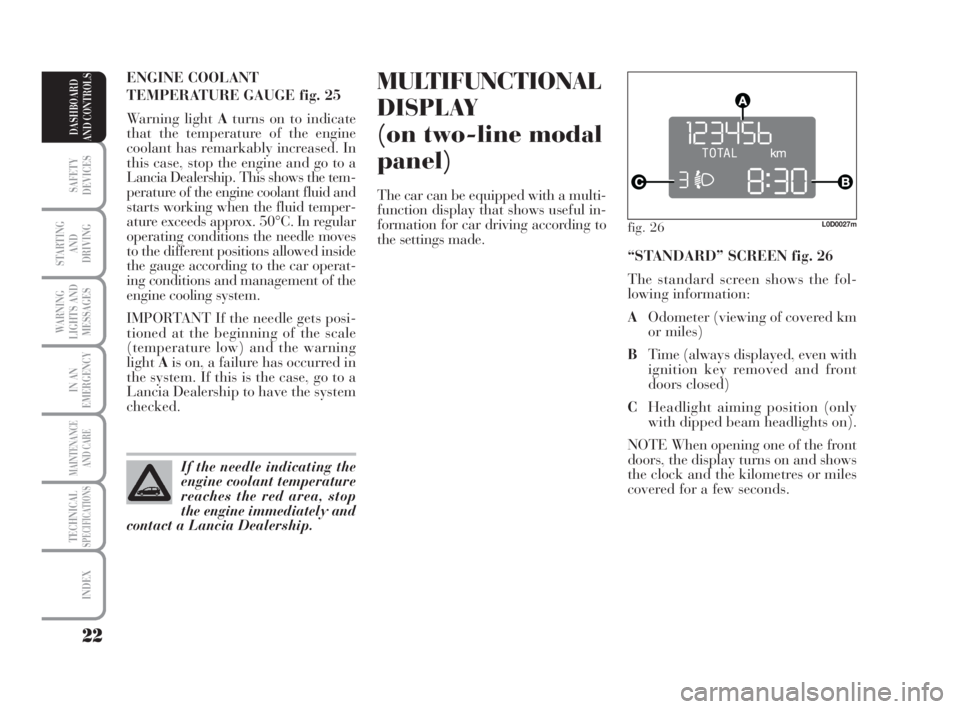
“STANDARD” SCREEN fig. 26
The standard screen shows the fol-
lowing information:
AOdometer (viewing of covered km
or miles)
BTime (always displayed, even with
ignition key removed and front
doors closed)
CHeadlight aiming position (only
with dipped beam headlights on).
NOTE When opening one of the front
doors, the display turns on and shows
the clock and the kilometres or miles
covered for a few seconds.
007-037 MUSA 3ed GB 12-11-2007 11:33 Pagina 22
Page 24 of 218
23
SAFETY
DEVICES
STARTING
AND
DRIVING
WARNING
LIGHTS AND
MESSAGES
IN AN
EMERGENCY
MAINTENANCE
AND CARE
TECHNICALSPECIFICATIONS
INDEX
DASHBOARD
AND CONTROLS
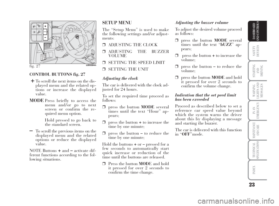
CONTROL BUTTONS fig. 27
+To scroll the next items on the dis-
played menu and the related op-
tions or increase the displayed
value.
MODEPress briefly to access the
menu and/or go to next
screen or confirm the re-
quired menu option.
Hold pressed to go back to
the standard screen.
–To scroll the previous items on the
displayed menu and the related
options or reduce the displayed
value.
NOTE Buttons
+and–activate dif-
ferent functions according to the fol-
lowing situations.Adjusting the buzzer volume
To adjust the desired volume proceed
as follows:
❒press the button MODEseveral
times until the text “bUZZ” ap-
pears;
❒press the button +to increase the
volume;
❒press the button –to reduce the
volume;
❒press the button MODEand hold
it pressed for over 2 seconds to
confirm the volume change.
Indication that the set peed limit
has been exceeded
Proceed as described below to set a
reference car speed value beyond
which the system warns the driver
about this by displaying a message
and starting the buzzer.
The car is delivered with this function
in “OFF”mode.
SETUP MENU
The “Setup Menu” is used to make
the following settings and/or adjust-
ments:
❒ADJUSTING THE CLOCK
❒ADJUSTING THE BUZZER
VOLUME
❒SETTING THE SPEED LIMIT
❒SETTING THE UNIT
Adjusting the clock
The car is delivered with the clock ad-
justed for 24 hours.
To set the required time proceed as
follows:
❒press the button MODEseveral
times until the text “Hour” ap-
pears;
❒press the button +to increase the
time by one minute;
❒press the button –to reduce the
time by one minute;
Hold the buttons +or–pressed for a
few seconds to automatically start
quick increase or reduction of the
time until the buttons are released.
❒Press the button MODE and hold
it pressed for over 2 seconds to
confirm the time change.
fig. 27L0D0384m
007-037 MUSA 3ed GB 12-11-2007 11:33 Pagina 23
Page 26 of 218
25
SAFETY
DEVICES
STARTING
AND
DRIVING
WARNING
LIGHTS AND
MESSAGES
IN AN
EMERGENCY
MAINTENANCE
AND CARE
TECHNICALSPECIFICATIONS
INDEX
DASHBOARD
AND CONTROLS
fig. 29L0D09000m
MULTIFUNCTIONAL
DISPLAY
(on three-line
comfort panel)
The car can be equipped with a mul-
tifunction display that shows useful
information for car driving according
to the settings made.
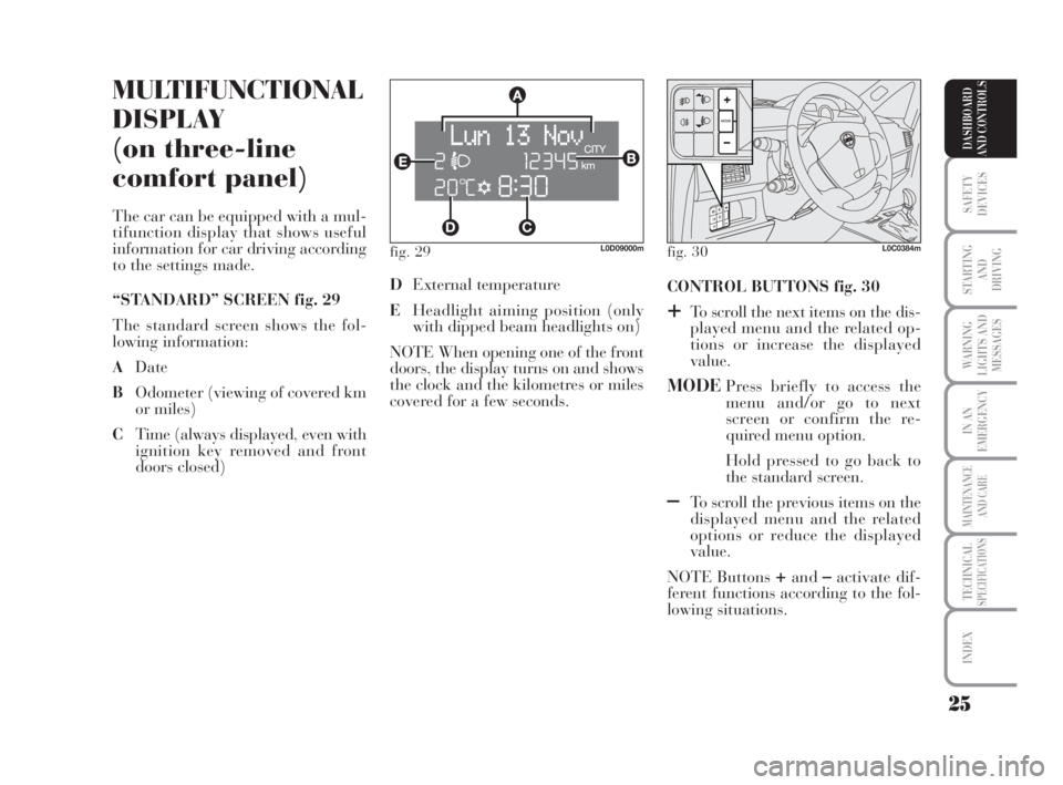
“STANDARD” SCREEN fig. 29
The standard screen shows the fol-
lowing information:
ADate
BOdometer (viewing of covered km
or miles)
CTime (always displayed, even with
ignition key removed and front
doors closed)CONTROL BUTTONS fig. 30
+To scroll the next items on the dis-
played menu and the related op-
tions or increase the displayed
value.
MODEPress briefly to access the
menu and/or go to next
screen or confirm the re-
quired menu option.
Hold pressed to go back to
the standard screen.
–To scroll the previous items on the
displayed menu and the related
options or reduce the displayed
value.
NOTE Buttons
+and–activate dif-
ferent functions according to the fol-
lowing situations. DExternal temperature
EHeadlight aiming position (only
with dipped beam headlights on)
NOTE When opening one of the front
doors, the display turns on and shows
the clock and the kilometres or miles
covered for a few seconds.
fig. 30L0C0384m
007-037 MUSA 3ed GB 12-11-2007 11:33 Pagina 25
Page 28 of 218
27
SAFETY
DEVICES
STARTING
AND
DRIVING
WARNING
LIGHTS AND
MESSAGES
IN AN
EMERGENCY
MAINTENANCE
AND CARE
TECHNICALSPECIFICATIONS
INDEX
DASHBOARD
AND CONTROLS
Day
YearMonth Example:
EXITING THE MENUSPEED BEEP.CLOCK SETTING
LIGHT SENS.TRIP B
CLOCK MODE
SETTING THE DATE
KEY
DIST. UNIT
VOL. BUTTONS
VOL. BUZZER SERVICE
LANGUAGETEMP. UNIT
Example:
– +
+– – –
+ +
–
–
+
+++
–––
+ +
–
MODE
brief button
pressing
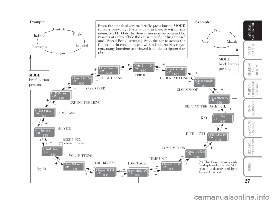
From the standard screen, briefly press button MODE
to start browsing. Press +or–to browse within the
menu. NOTE Only the short menu may be accessed for
reasons of safety while the car is moving (“Brightness”
and “Speed Beep” settings). Stop the car to access the
full menu. In cars equipped with a Connect Nav+ sys-
tem, many functions are viewed from the navigator dis-
play.
–
+ +
–
MODE
brief button
pressing
Deutsch
English
Español
Italiano
Português
Français
(*) This function may only
be displayed after the SBR
system is deactivated by a
Lancia Dealership.
fig. 31
+
– +
–+
–
+
–
+
–
CONSUMPTION BAG. PASS.
BELT BUZZ.
(*) where provided
007-037 MUSA 3ed GB 12-11-2007 11:33 Pagina 27
Page 30 of 218
29
SAFETY
DEVICES
STARTING
AND
DRIVING
WARNING
LIGHTS AND
MESSAGES
IN AN
EMERGENCY
MAINTENANCE
AND CARE
TECHNICALSPECIFICATIONS
INDEX
DASHBOARD
AND CONTROLS
Adjusting the sensitivity of the
automatic headlight sensor
(Light sensor) (where provided)
This function is used to adjust the
dusk sensor sensitivity according to
three levels (level 1 = minimum, level
2 = medium, level 3 = maximum); the
higher the sensitivity, the lower the
quantity of external light needed to
switch the headlights on. The car is
delivered with this function set to level
“2”.
To change this setting:
– briefly press button MODE: the pre-
viously set level flashes on the display;
– press button +or–for selecting the
desired level;
– briefly press button MODEto go
back to the menu screen or press the
button for a prolonged time to go back
to the standard screen without storing
the settings.Trip B On/Off (Trip B)
Through this option it is possible to
activate (On) or deactivate (Off) the
Trip B (partial trip) display.
For further information see section
“Trip computer”.
For activation / deactivation, proceed
as follows:
– briefly press button MODE: ON or
OFF flashes on the display (according
to previous setting);
– press button +or–for selecting the
desired value;
– briefly press button MODEto go
back to the menu screen or press the
button for a prolonged time to go back
to the standard screen without storing
the settings.Setting the clock (Set time)
This function enables setting of the
clock.
To set the clock proceed as follows:
– briefly press button MODE: the dis-
play shows the “hours” flashing;
– press button +or–to set the clock;
– briefly press button MODE: “min-
utes”starts flashing on the display;
– press button +or–to set the clock.
NOTE The setting increases or de-
creases by one unit each time button
+or–is pressed. Hold the button
pressed to automatically start a quick
increase/decrease of the set value.
Complete the setting by briefly press-
ing the button when the required set-
ting is approached.
– briefly press button MODEto go
back to the menu screen or press the
button for a prolonged time to go
back to the standard screen without
storing the settings.
007-037 MUSA 3ed GB 12-11-2007 11:33 Pagina 29
Page 31 of 218
30
SAFETY
DEVICES
STARTING
AND
DRIVING
WARNING
LIGHTS AND
MESSAGES
IN AN
EMERGENCY
MAINTENANCE
AND CARE
TECHNICALSPECIFICATIONS
INDEX
DASHBOARD
AND CONTROLS
Release of doors and tailgate (Key)
This function enables the release of
the front and rear doors, the release
of the driver's door only or the release
of all the doors including the tailgate.
To set the function, proceed as fol-
lows:
– press the MODEbutton for a short
time, the display shows “Open doors”,
“Op. drv.door” and “Open all”.
– press +or–to select; the selected
item will flash.
– Press MODEfor a short time to re-
turn to the menu screen or press the
button for a longer time to return to
the standard screen without confirm-
ing the selection. – briefly press button MODE: the
month starts flashing on the display;
– press button +or–to set the month;
– briefly press button MODE: the day
starts flashing on the display;
– press button +or–to set the day.
NOTE The setting increases or de-
creases by one unit each time button
+or–is pressed. Hold the button
pressed to start automatic quick in-
crease/decrease of the setting. Com-
plete the setting by briefly pressing
the button when the required setting
is approached.
– briefly press button MODEto go
back to the menu screen or press the
button for a prolonged time to go back
to the standard screen without storing
the settings. 12h/24h clock mode
(Clock mode)
This function enables setting the
screen to either 12 or 24 hour mode.
Proceed as follows:
– briefly press button MODE: 12h or
24h starts flashing on the display (de-
pending on the previously set para-
meter);
– press button +or–for selecting the
desired value;
– briefly press button MODEto go
back to the menu screen or press the
button for a prolonged time to go back
to the standard screen without storing
the settings.
Setting the date (Set Date)
This function enables updating the
date (year - month - day).
To update the date proceed as follows:
– briefly press button MODE: the
year starts flashing on the display;
– briefly press button +or–to set the
year;
007-037 MUSA 3ed GB 12-11-2007 11:33 Pagina 30
Page 52 of 218

51
SAFETY
DEVICES
STARTING
AND
DRIVING
WARNING
LIGHTS AND
MESSAGES
IN AN
EMERGENCY
MAINTENANCE
AND CARE
TECHNICALSPECIFICATIONS
INDEX
DASHBOARD
AND CONTROLS
DEMISTING/DEFROSTING
OF REAR WINDOW DEMISTER
AND ELECTRICAL DOOR
MIRRORS (where provided)
Press button C-fig. 61to enable this
function. When the function is active,
a led on the button goes on.
This is a timed function, which is au-
tomatically disabled by the system af-
ter a preset time. Press button C
again to disable the function in ad-
vance.
IMPORTANT Do not affix decals on
the inside of the rear window over the
heating filaments to avoid damage
that might cause it to stop working
properly.Regulating cooling
Proceed as follows:
❒stop internal air recirculation by
placing knob F-fig. 61on
Ú;
❒turn the rotating knurled ring B
clockwise to increase the temper-
ature;
❒turn knob Aanticlockwise to re-
duce the fan speed.
SERVICING THE SYSTEM
Run the climate control system for at
least 10 minutes every month during
the winter. Have the system inspected
at a Lancia Dealership before the
summer. CLIMATE CONTROL
(cooling and de-humidification)
Proceed as follows:
❒position the rotating knurled ring
B-fig. 61on the blue section to
select the required temperature;
❒turn knob Ato the required speed;
❒position the knurled ring Eon
«;
❒position the knob Fon
…;
❒press button D
√(the LED on the
button goes on).
038-094 MUSA 3ed GB 12-11-2007 11:35 Pagina 51
Page 56 of 218

55
SAFETY
DEVICES
STARTING
AND
DRIVING
WARNING
LIGHTS AND
MESSAGES
IN AN
EMERGENCY
MAINTENANCE
AND CARE
TECHNICALSPECIFICATIONS
INDEX
DASHBOARD
AND CONTROLS
The function is enabled when the pas-
senger compartment needs to be
heated as quickly as possible, thus us-
ing the system operating capacity at
best. This function uses the heating
fluid at max. temperature; air distri-
bution and fan speed are managed by
the system based on the existing con-
ditions.
Specifically, if the heating fluid is not
sufficiently warm, the fan will not
start up at the maximum speed im-
mediately to limit introduction of ex-
cessively cool air into the passenger
compartment.
All manual settings will be allowed
when this function is on.
To switch the function off, simply turn
the temperature knob anticlockwise
and set the required temperature.
❒FunctionLO(max. cooling):
select by turning the temperature
knob anticlockwise under the mini-
mum value (16 °C). This function is
activated from either the driver’s or
front passenger’s side or both (even by
selecting function MONO). This function has been included to
make temperature regulation easier
inside the passenger compartment
when the driver is the only passenger.
For separate management of temper-
atures and air distribution in the two
different areas of the passenger com-
partment, turn knobs Hor press but-
tonA-MONOagain when the LED on
the button is on.
Turn the knobs either all the way
right or left to the extreme HIorLO
position to use the maximum heating
or maximum cooling functions:
❒FunctionHI(max. heating):
select by turning the temperature
knob clockwise over the maximum
value (32 °C). This function is acti-
vated from either the driver’s or front
passenger’s side or both (even by se-
lecting function MONO). CONTROLS
Air temperature
adjusting knobs
H - N
Rotate the knobs
clockwise or anti-
clockwise to lift or
lower the air temper-
ature in the front left
area (knob N) and
right left area (knob
H) of the passenger
compartment respec-
tively.
As the system manages two zones in
the passenger compartment, the driver
and front passenger can set different
temperature values with a maximum
difference of 7 °C.
The temperature values set are high-
lighted on the display near the knobs.
Press button A(MONO) to automat-
ically align the temperature of the air
in the front passenger’s area and that
on the driver’s side. This means that
the same temperature can be set in
the two areas by turning knob Non
the driver’s side.
038-094 MUSA 3ed GB 12-11-2007 11:35 Pagina 55
Page 57 of 218
56
SAFETY
DEVICES
STARTING
AND
DRIVING
WARNING
LIGHTS AND
MESSAGES
IN AN
EMERGENCY
MAINTENANCE
AND CARE
TECHNICALSPECIFICATIONS
INDEX
DASHBOARD
AND CONTROLS
˙
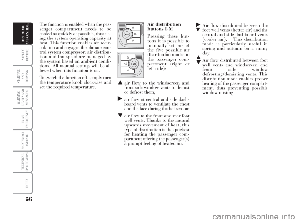
▼Air flow distributed between the
foot well vents (hotter air) and the
central and side dashboard vents
(cooler air). This distribution
mode is particularly useful in
spring and autumn on a sunny
day.
▲
▼Air flow distributed between foot
well vents and windscreen and
front side window
defrosting/demisting vents. This
distribution mode enables proper
heating of the passenger compart-
ment, thus preventing possible
window misting. The function is enabled when the pas-
senger compartment needs to be
cooled as quickly as possible, thus us-
ing the system operating capacity at
best. This function enables air recir-
culation and engages the climate con-
trol system compressor; air distribu-
tion and fan speed are managed by
the system based on ambient condi-
tions. All manual settings will be al-
lowed when this function is on.
To switch the function off, simply turn
the temperature knob clockwise and
set the required temperature.Air distribution
buttons I-M
Pressing these but-
tons it is possible to
manually set one of
the five possible air
distribution modes to
the passenger com-
partment (right or
left side):
▲air flow to the windscreen and
front side window vents to demist
or defrost them;
˙air flow at central and side dash-
board vents to ventilate the chest
and the face during the hot season;
▼air flow to the front and rear foot
well vents. Thanks to the natural
upwards movement of heat, this
type of distribution is the quickest
for heating the passenger com-
partment offering the passenger(s)
a prompt feeling of heated air.
038-094 MUSA 3ed GB 12-11-2007 11:35 Pagina 56
Page 78 of 218
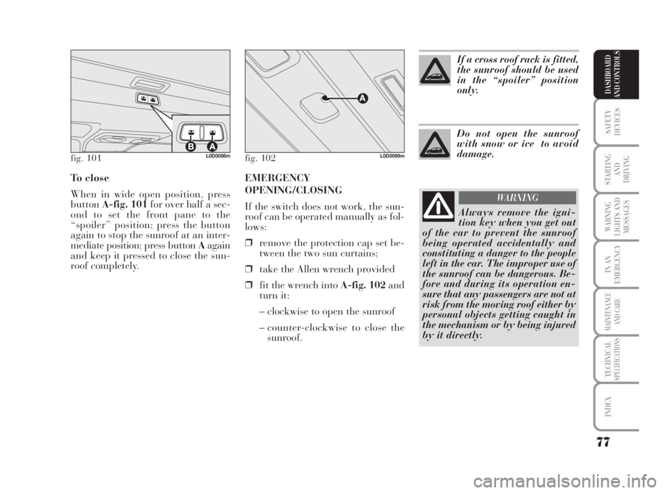
EMERGENCY
OPENING/CLOSING
If the switch does not work, the sun-
roof can be operated manually as fol-
lows:
❒remove the protection cap set be-
tween the two sun curtains;
❒take the Allen wrench provided
❒fit the wrench into A-fig. 102and
turn it:
– clockwise to open the sunroof
– counter-clockwise to close the
sunroof. To close
When in wide open position, press
buttonA-fig. 101for over half a sec-
ond to set the front pane to the
“spoiler” position; press the button
again to stop the sunroof at an inter-
mediate position; press button Aagain
and keep it pressed to close the sun-
roof completely.
77
SAFETY
DEVICES
STARTING
AND
DRIVING
WARNING
LIGHTS AND
MESSAGES
IN AN
EMERGENCY
MAINTENANCE
AND CARE
TECHNICALSPECIFICATIONS
INDEX
DASHBOARD
AND CONTROLS
fig. 101L0D0098mfig. 102L0D0099m
If a cross roof rack is fitted,
the sunroof should be used
in the “spoiler” position
only.
Do not open the sunroof
with snow or ice to avoid
damage.
Always remove the igni-
tion key when you get out
of the car to prevent the sunroof
being operated accidentally and
constituting a danger to the people
left in the car. The improper use of
the sunroof can be dangerous. Be-
fore and during its operation en-
sure that any passengers are not at
risk from the moving roof either by
personal objects getting caught in
the mechanism or by being injured
by it directly.
WARNING
038-094 MUSA 3ed GB 12-11-2007 11:35 Pagina 77