key Lancia Musa 2009 Owner handbook (in English)
[x] Cancel search | Manufacturer: LANCIA, Model Year: 2009, Model line: Musa, Model: Lancia Musa 2009Pages: 218, PDF Size: 3.7 MB
Page 21 of 218
20
SAFETY
DEVICES
STARTING
AND
DRIVING
WARNING
LIGHTS AND
MESSAGES
IN AN
EMERGENCY
MAINTENANCE
AND CARE
TECHNICALSPECIFICATIONS
INDEX
DASHBOARD
AND CONTROLS
IGNITION DEVICE
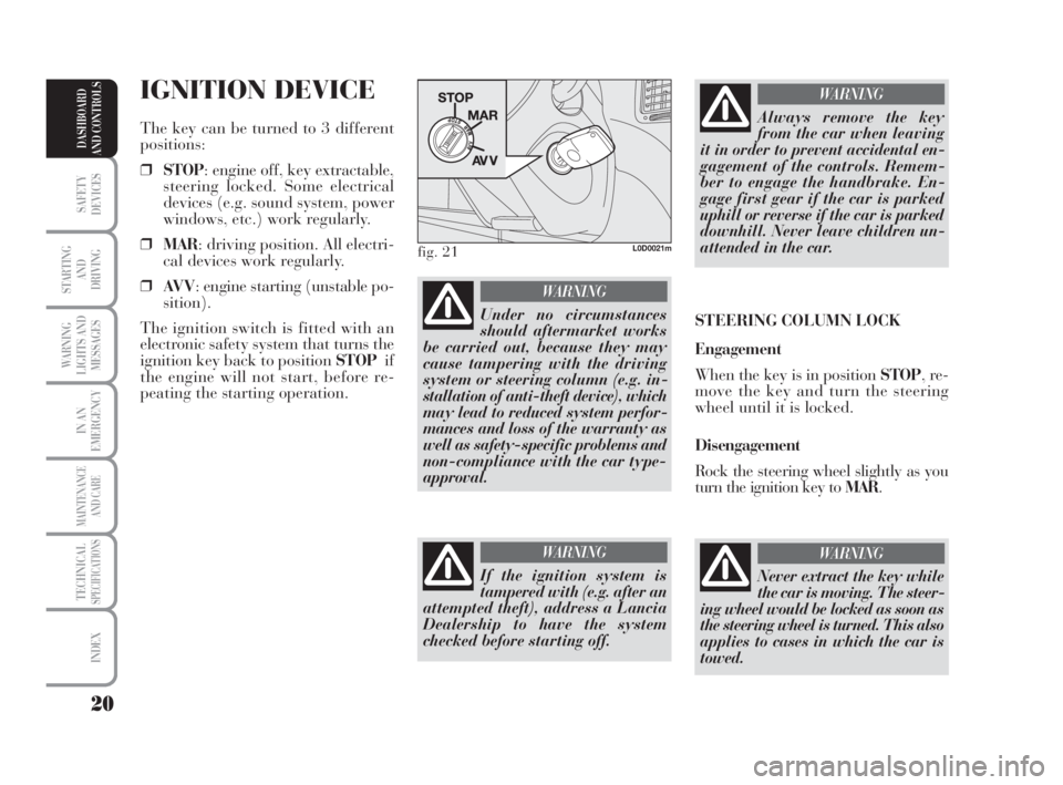
The key can be turned to 3 different
positions:
❒STOP: engine off, key extractable,
steering locked. Some electrical
devices (e.g. sound system, power
windows, etc.) work regularly.
❒MAR: driving position. All electri-
cal devices work regularly.
❒AV V: engine starting (unstable po-
sition).
The ignition switch is fitted with an
electronic safety system that turns the
ignition key back to position STOPif
the engine will not start, before re-
peating the starting operation.
Under no circumstances
should aftermarket works
be carried out, because they may
cause tampering with the driving
system or steering column (e.g. in-
stallation of anti-theft device), which
may lead to reduced system perfor-
mances and loss of the warranty as
well as safety-specific problems and
non-compliance with the car type-
approval.
WARNING
fig. 21L0D0021m
If the ignition system is
tampered with (e.g. after an
attempted theft), address a Lancia
Dealership to have the system
checked before starting off.
WARNING
Always remove the key
from the car when leaving
it in order to prevent accidental en-
gagement of the controls. Remem-
ber to engage the handbrake. En-
gage first gear if the car is parked
uphill or reverse if the car is parked
downhill. Never leave children un-
attended in the car.
WARNING
STEERING COLUMN LOCK
Engagement
When the key is in position STOP, re-
move the key and turn the steering
wheel until it is locked.
Disengagement
Rock the steering wheel slightly as you
turn the ignition key to MAR.
Never extract the key while
the car is moving. The steer-
ing wheel would be locked as soon as
the steering wheel is turned. This also
applies to cases in which the car is
towed.
WARNING
007-037 MUSA 1ed GB 10-07-2008 9:36 Pagina 20
Page 23 of 218
22
SAFETY
DEVICES
STARTING
AND
DRIVING
WARNING
LIGHTS AND
MESSAGES
IN AN
EMERGENCY
MAINTENANCE
AND CARE
TECHNICALSPECIFICATIONS
INDEX
DASHBOARD
AND CONTROLS
MULTIFUNCTIONAL
DISPLAY
(on two-line modal
panel)
The car can be equipped with a multi-
function display that shows useful in-
formation for car driving according to
the settings made. ENGINE COOLANT
TEMPERATURE GAUGE fig. 25
Warning light Aturns on to indicate
that the temperature of the engine
coolant has remarkably increased. In
this case, stop the engine and go to a
Lancia Dealership. This shows the tem-
perature of the engine coolant fluid and
starts working when the fluid temper-
ature exceeds approx. 50°C. In regular
operating conditions the needle moves
to the different positions allowed inside
the gauge according to the car operat-
ing conditions and management of the
engine cooling system.
IMPORTANT If the needle gets posi-
tioned at the beginning of the scale
(temperature low) and the warning
lightAis on, a failure has occurred in
the system. If this is the case, go to a
Lancia Dealership to have the system
checked.
If the needle indicating the
engine coolant temperature
reaches the red area, stop the
engine immediately and con-
tact a Lancia Dealership.
fig. 26L0D0027m
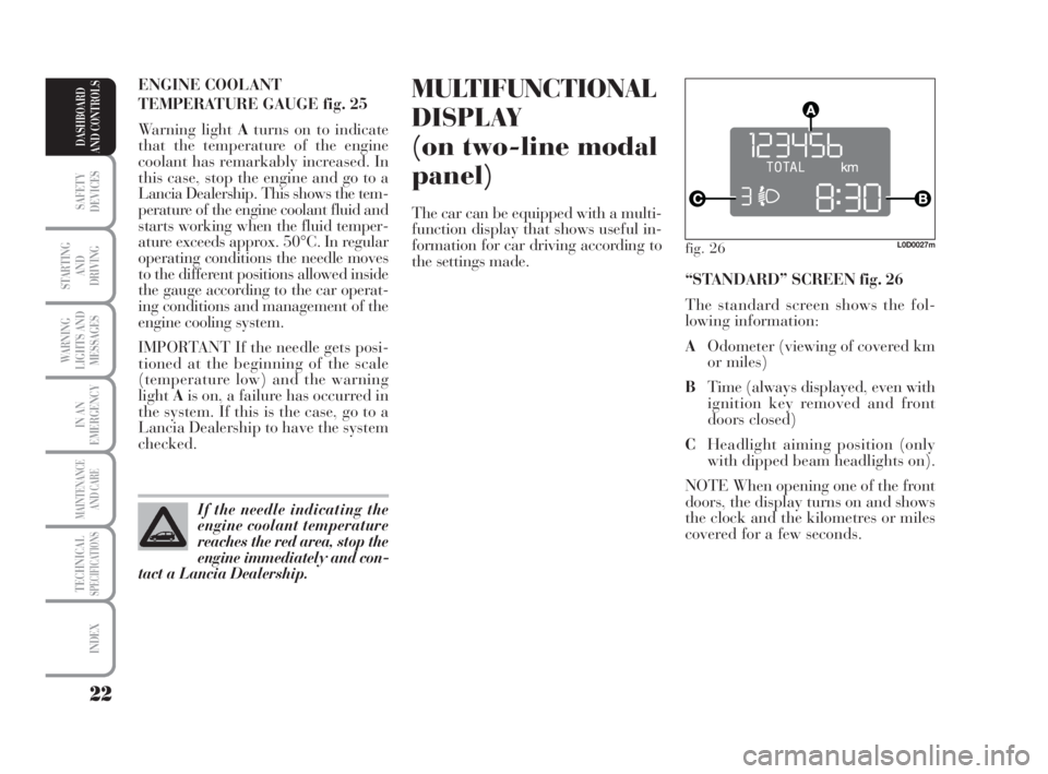
“STANDARD” SCREEN fig. 26
The standard screen shows the fol-
lowing information:
AOdometer (viewing of covered km
or miles)
BTime (always displayed, even with
ignition key removed and front
doors closed)
CHeadlight aiming position (only
with dipped beam headlights on).
NOTE When opening one of the front
doors, the display turns on and shows
the clock and the kilometres or miles
covered for a few seconds.
007-037 MUSA 1ed GB 10-07-2008 9:36 Pagina 22
Page 26 of 218
25
SAFETY
DEVICES
STARTING
AND
DRIVING
WARNING
LIGHTS AND
MESSAGES
IN AN
EMERGENCY
MAINTENANCE
AND CARE
TECHNICALSPECIFICATIONS
INDEX
DASHBOARD
AND CONTROLS
fig. 29L0D09000m
MULTIFUNCTIONAL
DISPLAY
(on three-line
comfort panel)
The car can be equipped with a mul-
tifunction display that shows useful
information for car driving according
to the settings made.
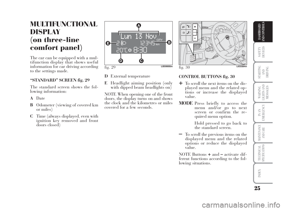
“STANDARD” SCREEN fig. 29
The standard screen shows the fol-
lowing information:
ADate
BOdometer (viewing of covered km
or miles)
CTime (always displayed, even with
ignition key removed and front
doors closed)CONTROL BUTTONS fig. 30
+To scroll the next items on the dis-
played menu and the related op-
tions or increase the displayed
value.
MODEPress briefly to access the
menu and/or go to next
screen or confirm the re-
quired menu option.
Hold pressed to go back to
the standard screen.
–To scroll the previous items on the
displayed menu and the related
options or reduce the displayed
value.
NOTE Buttons
+and–activate dif-
ferent functions according to the fol-
lowing situations. DExternal temperature
EHeadlight aiming position (only
with dipped beam headlights on)
NOTE When opening one of the front
doors, the display turns on and shows
the clock and the kilometres or miles
covered for a few seconds.
fig. 30L0C0384m
007-037 MUSA 1ed GB 10-07-2008 9:36 Pagina 25
Page 28 of 218
27
SAFETY
DEVICES
STARTING
AND
DRIVING
WARNING
LIGHTS AND
MESSAGES
IN AN
EMERGENCY
MAINTENANCE
AND CARE
TECHNICALSPECIFICATIONS
INDEX
DASHBOARD
AND CONTROLS
Day
YearMonth Example:
EXITING THE MENUSPEED BEEP.CLOCK SETTING
LIGHT SENS.TRIP B
CLOCK MODE
SETTING THE DATE
KEY
DIST. UNIT
VOL. BUTTONS
VOL. BUZZER SERVICE
LANGUAGETEMP. UNIT
Example:
– +
+– – –
+ +
–
–
+
+++
–––
+ +
–
MODE
brief button
pressing
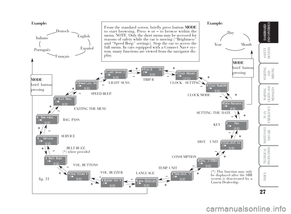
From the standard screen, briefly press button MODE
to start browsing. Press +or–to browse within the
menu. NOTE Only the short menu may be accessed for
reasons of safety while the car is moving (“Brightness”
and “Speed Beep” settings). Stop the car to access the
full menu. In cars equipped with a Connect Nav+ sys-
tem, many functions are viewed from the navigator dis-
play.
–
+ +
–
MODE
brief button
pressing
Deutsch
English
Español
Italiano
Português
Français
(*) This function may only
be displayed after the SBR
system is deactivated by a
Lancia Dealership.
fig. 31
+
– +
–+
–
+
–
+
–
CONSUMPTION BAG. PASS.
BELT BUZZ.
(*) where provided
007-037 MUSA 1ed GB 10-07-2008 9:36 Pagina 27
Page 31 of 218
30
SAFETY
DEVICES
STARTING
AND
DRIVING
WARNING
LIGHTS AND
MESSAGES
IN AN
EMERGENCY
MAINTENANCE
AND CARE
TECHNICALSPECIFICATIONS
INDEX
DASHBOARD
AND CONTROLS
Release of doors and tailgate (Key)
This function enables the release of
the front and rear doors, the release
of the driver's door only or the release
of all the doors including the tailgate.
To set the function, proceed as fol-
lows:
– press the MODEbutton for a short
time, the display shows “Open doors”,
“Op. drv.door” and “Open all”.
– press +or–to select; the selected
item will flash.
– Press MODEfor a short time to re-
turn to the menu screen or press the
button for a longer time to return to
the standard screen without confirm-
ing the selection. – briefly press button MODE: the
month starts flashing on the display;
– press button +or–to set the month;
– briefly press button MODE: the day
starts flashing on the display;
– press button +or–to set the day.
NOTE The setting increases or de-
creases by one unit each time button
+or–is pressed. Hold the button
pressed to start automatic quick in-
crease/decrease of the setting. Com-
plete the setting by briefly pressing
the button when the required setting
is approached.
– briefly press button MODEto go
back to the menu screen or press the
button for a prolonged time to go back
to the standard screen without storing
the settings. 12h/24h clock mode
(Clock mode)
This function enables setting the
screen to either 12 or 24 hour mode.
Proceed as follows:
– briefly press button MODE: 12h or
24h starts flashing on the display (de-
pending on the previously set para-
meter);
– press button +or–for selecting the
desired value;
– briefly press button MODEto go
back to the menu screen or press the
button for a prolonged time to go back
to the standard screen without storing
the settings.
Setting the date (Set Date)
This function enables updating the
date (year - month - day).
To update the date proceed as follows:
– briefly press button MODE: the year
starts flashing on the display;
– briefly press button +or–to set the
year;
007-037 MUSA 1ed GB 10-07-2008 9:36 Pagina 30
Page 34 of 218
33
SAFETY
DEVICES
STARTING
AND
DRIVING
WARNING
LIGHTS AND
MESSAGES
IN AN
EMERGENCY
MAINTENANCE
AND CARE
TECHNICALSPECIFICATIONS
INDEX
DASHBOARD
AND CONTROLS
Adjusting the button volume
(Button Vol.)
This function enables setting the vol-
ume of the roger-beep accompanying
the activation of buttons MODE,+
and–according to 8 levels.
To adjust the desired volume proceed
as follows:
– briefly press button MODE: the pre-
viously set volume “level” starts flash-
ing on the display;
– press button +or–to set the volume
level;
– briefly press button MODEto go
back to the menu screen or press the
button for a prolonged time to go
back to the standard screen without
storing the settings.
S.B.R. buzzer reactivation
(Belt Buzzer) (where provided)
This function can only be displayed
after Lancia Dealership has deacti-
vated the S.B.R. system (see para-
graph “S.B.R. system” in section
“Safety devices”).The indications will appear more fre-
quently when there are 200 km left.
For 1.3 Multijet versions refer to the
instructions provided in the “Sched-
uled Servicing Plan” in section “Car
Maintenance” for air filter, engine oil
and engine oil filter replacement. The
indication will appear in kilometres or
miles according to the unit settings.
When the next scheduled servicing is
near, the message “Service” will ap-
pear on the display followed by the
number of kilometres or miles or days
left before servicing when the key is
turned to MAR. The “Scheduled Ser-
vicing” message shows information in
either kilometres (km) or miles (mi)
or in days (dd) depending on the
deadline showing up first. Go to the
Lancia Dealership where the servic-
ing operations envisaged in the
“Scheduled Service Plan” or “Yearly
Inspection Plan” will be performed
and the message will be reset. Scheduled Servicing (Service)
This function enables viewing of in-
formation on proper car servicing de-
pending on the kilometres travelled or
daily intervals.
This information is consulted as fol-
lows:
– briefly press button MODE: the dis-
play shows service requirements in
km or mi according to the previous
setting (see paragraph “Distance
unit”);
– press button +or–to view the ser-
vice interval in days;
– briefly press button MODEto go
back to the menu screen or press the
button for a prolonged time to go back
to the standard screen.
NOTE According to the “Scheduled
Servicing Plan” the car must be ser-
viced every 20,000 km (or equivalent
mileage) or on a yearly basis. This
message appears automatically when
the key is positioned on MARafter
travelling for 2,000 km (or equivalent
mileage) or 30 days after the dead-
line. It appears every 200 km (or
equivalent mileage) or 3 days.
007-037 MUSA 1ed GB 10-07-2008 9:36 Pagina 33
Page 36 of 218
35
SAFETY
DEVICES
STARTING
AND
DRIVING
WARNING
LIGHTS AND
MESSAGES
IN AN
EMERGENCY
MAINTENANCE
AND CARE
TECHNICALSPECIFICATIONS
INDEX
DASHBOARD
AND CONTROLS
Exiting the Menu
This is the last function that closes the
setting cycle listed in the initial menu
screen.
Briefly press button MODEto go back
to the standard screen without storing
the settings.
Press button +to return to the first
menu option (Speed Beep).Both functions can be reset (to start a
new trip).
The “General Trip” function is used
to display information relating to:
– Range
– Trip distance
– Average consumption
– Instant consumption
– Average speed
– Travel time (driving time).
The “Trip B” function is used to dis-
play information relating to:
– Trip distance B
– Average consumption B
– Average speed B
– Travel time B (driving time).
NOTE “Trip B” functions may be dis-
abled (see “Trip B on”). “Range” and
“Instantaneous consumption” cannot
be reset.TRIP COMPUTER
(where provided)
General features
The “Trip computer” is used to dis-
play information on car operation
when the key is turned to MAR. This
function includes a “General trip”
system that monitors the “entire mis-
sion” (trip) of the car and the “Trip
B” system that monitors the partial
mission of the car. The former func-
tion is part of the entire mission (as il-
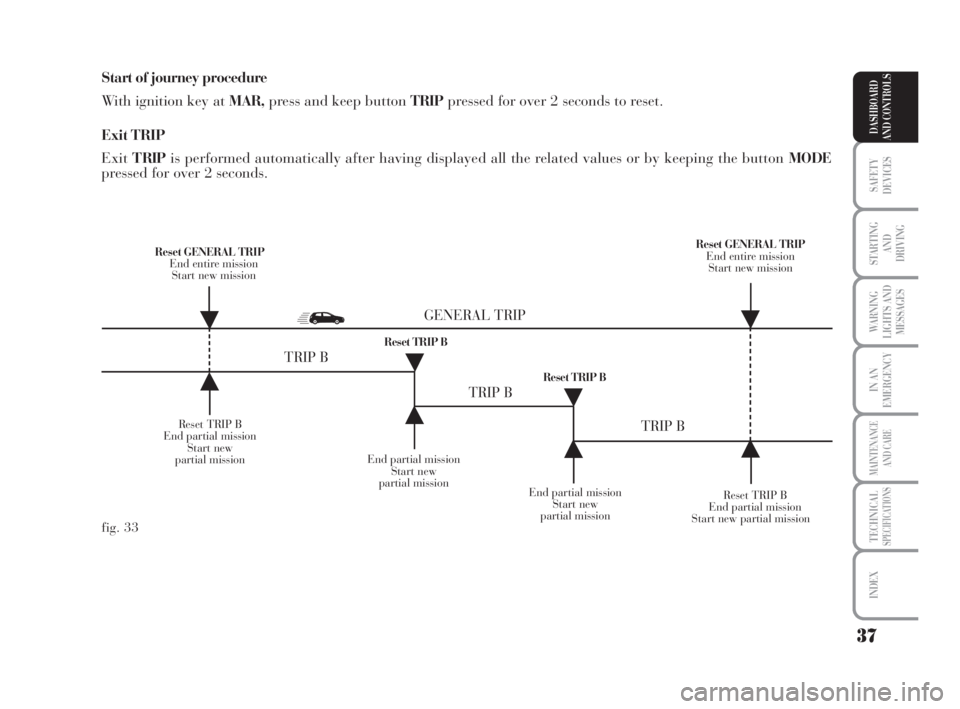
lustrated in fig. 33).
007-037 MUSA 1ed GB 10-07-2008 9:36 Pagina 35
Page 37 of 218
36
SAFETY
DEVICES
STARTING
AND
DRIVING
WARNING
LIGHTS AND
MESSAGES
IN AN
EMERGENCY
MAINTENANCE
AND CARE
TECHNICALSPECIFICATIONS
INDEX
DASHBOARD
AND CONTROLS
New mission
The new mission begins after:
– “manual” resetting by the user, by
pressing the relevant button;
– “automatic” resetting, when the
“Trip distance” reaches 9999.9 km or
when the “Travel time” reaches 99.59
(99 hours and 59 minutes);
– disconnection/reconnection of the
battery.
IMPORTANT The reset operations
performed after the “General Trip”
message appears are used to also re-
set the “Trip B”, which, on its turn, is
used to reset the values of the corre-
sponding function. Travel time
This value shows the time elapsed
since the start of a new mission.
IMPORTANT If information is not
available, the message “----” will ap-
pear instead of the Trip Computer
values. Displaying of the values will
be resumed regularly when normal
operation is restored without resetting
the values displayed before the failure
nor starting a new mission.
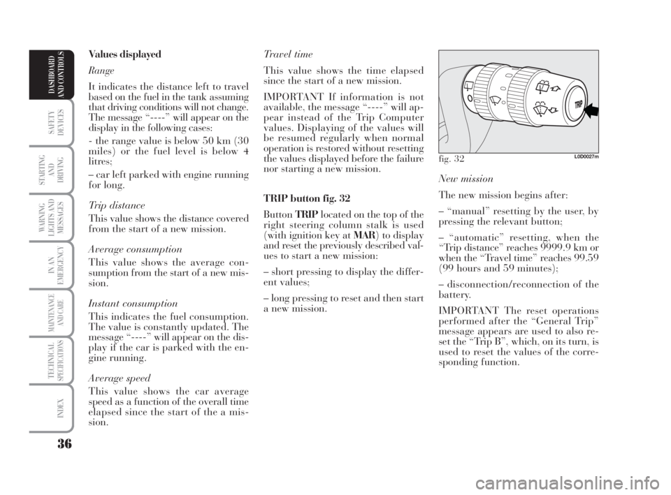
TRIP button fig. 32
ButtonTRIPlocated on the top of the
right steering column stalk is used
(with ignition key at MAR) to display
and reset the previously described val-
ues to start a new mission:
– short pressing to display the differ-
ent values;
– long pressing to reset and then start
a new mission. Values displayed
Range
It indicates the distance left to travel
based on the fuel in the tank assuming
that driving conditions will not change.
The message “----” will appear on the
display in the following cases:
- the range value is below 50 km (30
miles) or the fuel level is below 4
litres;
– car left parked with engine running
for long.
Trip distance
This value shows the distance covered
from the start of a new mission.
Average consumption
This value shows the average con-
sumption from the start of a new mis-
sion.
Instant consumption
This indicates the fuel consumption.
The value is constantly updated. The
message “----” will appear on the dis-
play if the car is parked with the en-
gine running.
Average speed
This value shows the car average
speed as a function of the overall time
elapsed since the start of the a mis-
sion.
fig. 32L0D0027m
007-037 MUSA 1ed GB 10-07-2008 9:36 Pagina 36
Page 38 of 218
37
SAFETY
DEVICES
STARTING
AND
DRIVING
WARNING
LIGHTS AND
MESSAGES
IN AN
EMERGENCY
MAINTENANCE
AND CARE
TECHNICALSPECIFICATIONS
INDEX
DASHBOARD
AND CONTROLS
Start of journey procedure
With ignition key at MAR,press and keep button TRIPpressed for over 2 seconds to reset.
Exit TRIP
ExitT RIPis performed automatically after having displayed all the related values or by keeping the button MODE
pressed for over 2 seconds.
Reset TRIP B
End partial mission
Start new
partial missionEnd partial mission
Start new
partial mission
Reset TRIP B
End partial mission
Start new partial mission Reset GENERAL TRIP
End entire mission
Start new missionReset GENERAL TRIP
End entire mission
Start new mission
End partial mission
Start new
partial mission Reset TRIP B
Reset TRIP B
TRIP B
TRIP B
TRIP B GENERAL TRIP
˙
˙
˙
˙
˙
˙˙
˙
fig. 33
007-037 MUSA 1ed GB 10-07-2008 9:36 Pagina 37
Page 47 of 218
46
SAFETY
DEVICES
STARTING
AND
DRIVING
WARNING
LIGHTS AND
MESSAGES
IN AN
EMERGENCY
MAINTENANCE
AND CARE
TECHNICALSPECIFICATIONS
INDEX
DASHBOARD
AND CONTROLS
Adjust the mirrors after the car has
been stopped and the hand brake en-
gaged.
The electric demisting device of the
mirrors is automatically engaged
when the rear window demister is ac-
tivated.
Folding
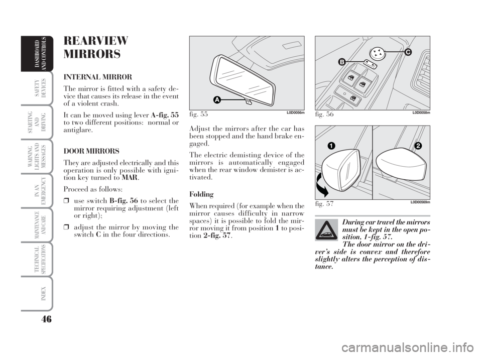
When required (for example when the
mirror causes difficulty in narrow
spaces) it is possible to fold the mir-
ror moving it from position 1to posi-
tion2-fig. 57.
REARVIEW
MIRRORS
INTERNAL MIRROR
The mirror is fitted with a safety de-
vice that causes its release in the event
of a violent crash.
It can be moved using lever A-fig. 55
to two different positions: normal or
antiglare.
DOOR MIRRORS
They are adjusted electrically and this
operation is only possible with igni-
tion key turned to MAR.
Proceed as follows:
❒use switch B-fig. 56to select the
mirror requiring adjustment (left
or right);
❒adjust the mirror by moving the
switchCin the four directions.
fig. 55L0D0056m
During car travel the mirrors
must be kept in the open po-
sition, 1-fig. 57.
The door mirror on the dri-
ver’s side is convex and therefore
slightly alters the perception of dis-
tance.
fig. 56L0D0058m
fig. 57L0D00569m
038-094 MUSA 1ed GB 11-07-2008 14:10 Pagina 46