sensor Lancia Musa 2009 Owner handbook (in English)
[x] Cancel search | Manufacturer: LANCIA, Model Year: 2009, Model line: Musa, Model: Lancia Musa 2009Pages: 218, PDF Size: 3.7 MB
Page 4 of 218
USE OF ENVIRONMENT-FRIENDLY MATERIALS
None of the components installed on LANCIA Musa contains asbestos. The padding and air conditioning system are
CFC-free (Chlorofluorocarbons), these gases being reliable for the depletion of the ozone layer. Dying agents and anti-
corrosion coating of the bolts and screws no longer contain cadmium, which pollutes the air and waterbeds.
EMISSION-REDUCING DEVICES (petrol engines)
Three-way catalytic converter (catalytic converter)
The exhaust system features a catalyst made with alloys of noble metals. It is installed in a stainless steel housing which
is resistant to high operating temperatures.
The catalyst converts the unburnt hydrocarbons, carbon oxide and nitrogen oxides that are present in the exhaust gases
(although in small quantities thanks to electronic injection ignition systems) into non-polluting compounds.
As the catalytic converter reaches high temperatures during car operation, we recommend that the car should not be
parked on materials that may pose a risk of flammability (e.g. paper, fuel oils, dry grass or leaves, etc.).
Lambda sensors
These sensors (Lambda) detect the oxygen content in the exhaust gases. Lambda sensors produce a signal which is
used by the electronic control unit of the injection and ignition system for regulating the air-fuel mix.
Fuel evaporation system
Even when the engine is not running, it is not possible to prevent the formation of petrol vapours. For this reason, a
system has been developed to “catch” these vapours in a special activated carbon vessel.
While the engine is running, these vapours are aspirated and delivered to combustion.
001-006 MUSA 1ed GB 10-07-2008 9:36 Pagina 3
Page 8 of 218
7
SAFETY
DEVICES
STARTING
AND
DRIVING
WARNING
LIGHTS AND
MESSAGES
IN AN
EMERGENCY
MAINTENANCE
AND CARE
TECHNICALSPECIFICATIONS
INDEX
DASHBOARD
AND CONTROLSDASHBOARD ........................................................ 8
INSTRUMENT PANEL.......................................... 10
SYMBOLS ............................................................. 11
THE LANCIA CODE SYSTEM .............................. 11
THE KEY AND DOOR LOCKING KIT ................. 13
IGNITION DEVICE .............................................. 20
INSTRUMENTS ................................................... 21
MULTIFUNCTIONAL DISPLAY
(on two-line modal panel) ...................................... 22
MULTIFUNCTIONAL DISPLAY
(on three-line modal panel).................................... 25
ADJUSTING THE SEATS ..................................... 38
HEAD RESTRAINTS ............................................ 44
ADJUSTING THE STEERING WHEEL ............... 45
REARVIEW MIRRORS .......................................... 46
HEATING/CLIMATE CONTROL SYSTEM .......... 47
MANUAL CLIMATE CONTROL SYSTEM ........... 48
AUTOMATIC CLIMATE CONTROL
SYSTEM (TWO-ZONE) ....................................... 52
EXTERNAL LIGHTS ........................................... 62
WINDOW WASHING ............................................ 64
CRUISE CONTROL ............................................. 67CEILING LIGHTS ................................................. 69
LIGHT CONTROL BUTTONS .............................. 71
FUEL CUT-OFF INERTIAL SWITCH ................... 72
INTERNAL EQUIPMENT .................................... 73
SMOKERS KIT ...................................................... 75
SUN VISORS ......................................................... 76
SUNROOF ............................................................ 76
POWER WINDOWS ............................................. 78
BOOT .................................................................... 80
BONNET ............................................................... 82
ROOF BARS .......................................................... 83
HEADLIGHTS ...................................................... 84
ABS SYSTEM ....................................................... 85
EOBD SYSTEM .................................................... 86
SOUND SYSTEM .................................................. 87
ACCESSORIES PURCHASED BY THE OWNER .. 88
“DUALDRIVE” ELECTRIC POWER
STEERING SYSTEM ............................................ 89
PARKING SENSORS ............................................ 90
REFUELLING ...................................................... 92
ENVIRONMENTAL PROTECTION ..................... 94
DASHBOARD AND CONTROLS
007-037 MUSA 1ed GB 10-07-2008 9:36 Pagina 7
Page 27 of 218
26
SAFETY
DEVICES
STARTING
AND
DRIVING
WARNING
LIGHTS AND
MESSAGES
IN AN
EMERGENCY
MAINTENANCE
AND CARE
TECHNICALSPECIFICATIONS
INDEX
DASHBOARD
AND CONTROLS
Adjustment of
headlight aiming device (only with
dipped beam headlights on)
- when the standard screen is enabled,
the headlight aiming device can be
regulated (refer to paragraph “Head-
lights” in this section).
Setup menu
- to scroll the previous and next items
in the menu;
- to increase or decrease values dur-
ing setting operations.
SETUP MENU fig. 31
The menu comprises a series of func-
tions arranged in a cycle which can be
selected through buttons
+and–to
access the different “select” opera-
tions and settings (setup) described in
the following paragraphs.
The setup menu is activated by press-
ing briefly button MODE.
Intermittent pressing of buttons
+and–enables scrolling of the setup menu
options.
Handling modes are different accord-
ing to the characteristic of the option
selected.Selecting the “Set Date”
and “Set time”
– Briefly press button MODEto select
the first value to be changed (e.g.
hours /minutes or year / month /
day).
– Press buttons
+and–(by single
pressing) to select the new setting.
– Briefly press button MODEto store
the new setting and at the same time
go to the next setup menu option. If
the processed option is the last one,
the system brings you back to the pre-
viously selected option of the main
menu.
Prolonged pressing of the
button MODE enables:
– exiting the setup menu page and
saving of the changes already stored
by the driver (and confirmed by
briefly pressing the button MODE).
The setup menu page is timed. Only
the changes saved by the user by
briefly pressing MODEare saved
when the menu is automatically
closed. NOTE If the Connect Nav+ system is
installed, only the following functions
can be adjusted/set from the Instru-
ment Panel: “Brightness”, “Speed
Beep”, Light Sensors” (where pro-
vided), “Seat belt Buzzer” and “Pas-
senger’s Airbag”. The other functions
are displayed on the Connect Nav+
system which is used to adjust/set
them.
Selecting a menu option
– Briefly press button MODEto select
the menu option that needs to be
changed.
– Press buttons
+and–(by single
pressing) to select the new setting.
– Briefly press button MODEto store
the new setting and at the same time
go back to the previously selected
menu option.
007-037 MUSA 1ed GB 10-07-2008 9:36 Pagina 26
Page 30 of 218
29
SAFETY
DEVICES
STARTING
AND
DRIVING
WARNING
LIGHTS AND
MESSAGES
IN AN
EMERGENCY
MAINTENANCE
AND CARE
TECHNICALSPECIFICATIONS
INDEX
DASHBOARD
AND CONTROLS
Adjusting the sensitivity of the
automatic headlight sensor (Light
sensor) (where provided)
This function is used to adjust the
dusk sensor sensitivity according to
three levels (level 1 = minimum, level
2 = medium, level 3 = maximum); the
higher the sensitivity, the lower the
quantity of external light needed to
switch the headlights on. The car is
delivered with this function set to level
“2”.
To change this setting:
– briefly press button MODE: the pre-
viously set level flashes on the display;
– press button +or–for selecting the
desired level;
– briefly press button MODEto go
back to the menu screen or press the
button for a prolonged time to go back
to the standard screen without storing
the settings.Trip B On/Off (Trip B)
Through this option it is possible to
activate (On) or deactivate (Off) the
Trip B (partial trip) display.
For further information see section
“Trip computer”.
For activation / deactivation, proceed
as follows:
– briefly press button MODE: ON or
OFF flashes on the display (according
to previous setting);
– press button +or–for selecting the
desired value;
– briefly press button MODEto go
back to the menu screen or press the
button for a prolonged time to go back
to the standard screen without storing
the settings.Setting the clock (Set time)
This function enables setting of the
clock.
To set the clock proceed as follows:
– briefly press button MODE: the dis-
play shows the “hours” flashing;
– press button +or–to set the clock;
– briefly press button MODE: “min-
utes”starts flashing on the display;
– press button +or–to set the clock.
NOTE The setting increases or de-
creases by one unit each time button
+or–is pressed. Hold the button
pressed to automatically start a quick
increase/decrease of the set value.
Complete the setting by briefly press-
ing the button when the required set-
ting is approached.
– briefly press button MODEto go
back to the menu screen or press the
button for a prolonged time to go
back to the standard screen without
storing the settings.
007-037 MUSA 1ed GB 10-07-2008 9:36 Pagina 29
Page 64 of 218
63
SAFETY
DEVICES
STARTING
AND
DRIVING
WARNING
LIGHTS AND
MESSAGES
IN AN
EMERGENCY
MAINTENANCE
AND CARE
TECHNICALSPECIFICATIONS
INDEX
DASHBOARD
AND CONTROLS
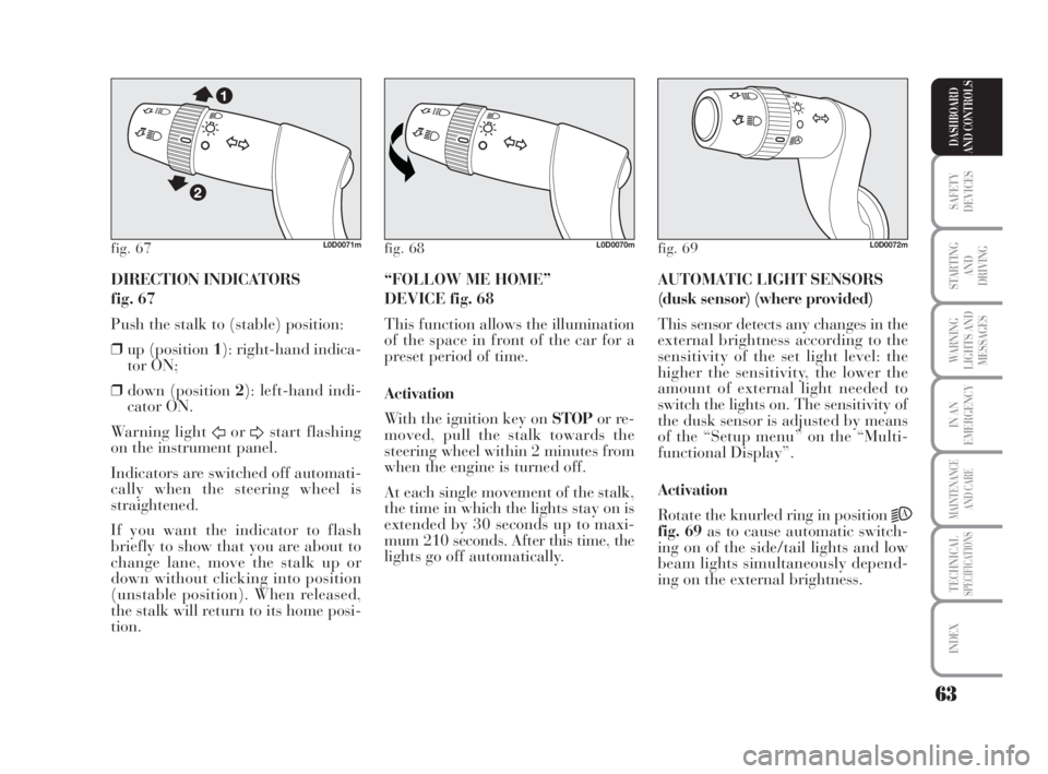
DIRECTION INDICATORS
fig. 67
Push the stalk to (stable) position:
❒up (position 1): right-hand indica-
tor ON;
❒down (position 2): left-hand indi-
cator ON.
Warning light
ForDstart flashing
on the instrument panel.
Indicators are switched off automati-
cally when the steering wheel is
straightened.
If you want the indicator to flash
briefly to show that you are about to
change lane, move the stalk up or
down without clicking into position
(unstable position). When released,
the stalk will return to its home posi-
tion.AUTOMATIC LIGHT SENSORS
(dusk sensor) (where provided)
This sensor detects any changes in the
external brightness according to the
sensitivity of the set light level: the
higher the sensitivity, the lower the
amount of external light needed to
switch the lights on. The sensitivity of
the dusk sensor is adjusted by means
of the “Setup menu” on the “Multi-
functional Display”.
Activation
Rotate the knurled ring in position
2A
fig. 69as to cause automatic switch-
ing on of the side/tail lights and low
beam lights simultaneously depend-
ing on the external brightness. “FOLLOW ME HOME”
DEVICE fig. 68
This function allows the illumination
of the space in front of the car for a
preset period of time.
Activation
With the ignition key on STOPor re-
moved, pull the stalk towards the
steering wheel within 2 minutes from
when the engine is turned off.
At each single movement of the stalk,
the time in which the lights stay on is
extended by 30 seconds up to maxi-
mum 210 seconds. After this time, the
lights go off automatically.
fig. 67L0D0071mfig. 68L0D0070mfig. 69L0D0072m
038-094 MUSA 1ed GB 11-07-2008 14:10 Pagina 63
Page 65 of 218
64
SAFETY
DEVICES
STARTING
AND
DRIVING
WARNING
LIGHTS AND
MESSAGES
IN AN
EMERGENCY
MAINTENANCE
AND CARE
TECHNICALSPECIFICATIONS
INDEX
DASHBOARD
AND CONTROLS
WINDOW
WASHING
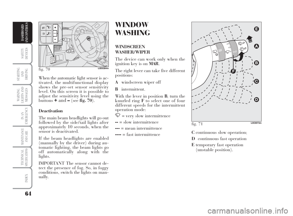
WINDSCREEN
WASHER/WIPER
The device can work only when the
ignition key is on MAR.
The right lever can take five different
positions:
Awindscreen wiper off
Bintermittent.
With the lever in position B, turn the
knurled ring Fto select one of four
different speeds for the intermittent
operation mode:
,= very slow intermittence
--= slow intermittence
---= mean intermittence
----= fast intermittence When the automatic light sensor is ac-
tivated, the multifunctional display
shows the pre-set sensor sensitivity
level. On this screen it is possible to
adjust the sensitivity level using the
buttons
+and–(seefig. 70).
Deactivation
The main beam headlights will go out
followed by the side/tail lights after
approximately 10 seconds, when the
sensor is deactivated.
If the beam headlights are enabled
(manually by the driver) during au-
tomatic lighting, the beam lights go
off automatically along with the
lights.
IMPORTANT The sensor cannot de-
tect the presence of fog. So, in foggy
conditions, switch the lights on man-
ually.
fig. 70L0D0384m
fig. 71L0C0073m
Ccontinuous slow operation;
Dcontinuous fast operation
Etemporary fast operation
(unstable position).
038-094 MUSA 1ed GB 11-07-2008 14:10 Pagina 64
Page 66 of 218
65
SAFETY
DEVICES
STARTING
AND
DRIVING
WARNING
LIGHTS AND
MESSAGES
IN AN
EMERGENCY
MAINTENANCE
AND CARE
TECHNICALSPECIFICATIONS
INDEX
DASHBOARD
AND CONTROLS
Operation in position Eis limited to
the time during which the lever is
kept in that position manually..
When released, the stalk will return
to position Aand the wiper will be
automatically stopped.
IMPORTANT Replace wiper blades
as specified in section “Car
maintenance”.RAIN SENSOR
(where provided)
The rain sensor is located behind the
driving mirror in contact with the
windscreen and has the purpose of
automatically adjust the frequency of
the windscreen wiper strokes as to the
rain intensity.
IMPORTANT Keep the window clean
in the sensor area.
Activation
Move the right lever down by one
click.
The activation of the rain sensor is
signalled by a control acquisition
“stroke”.
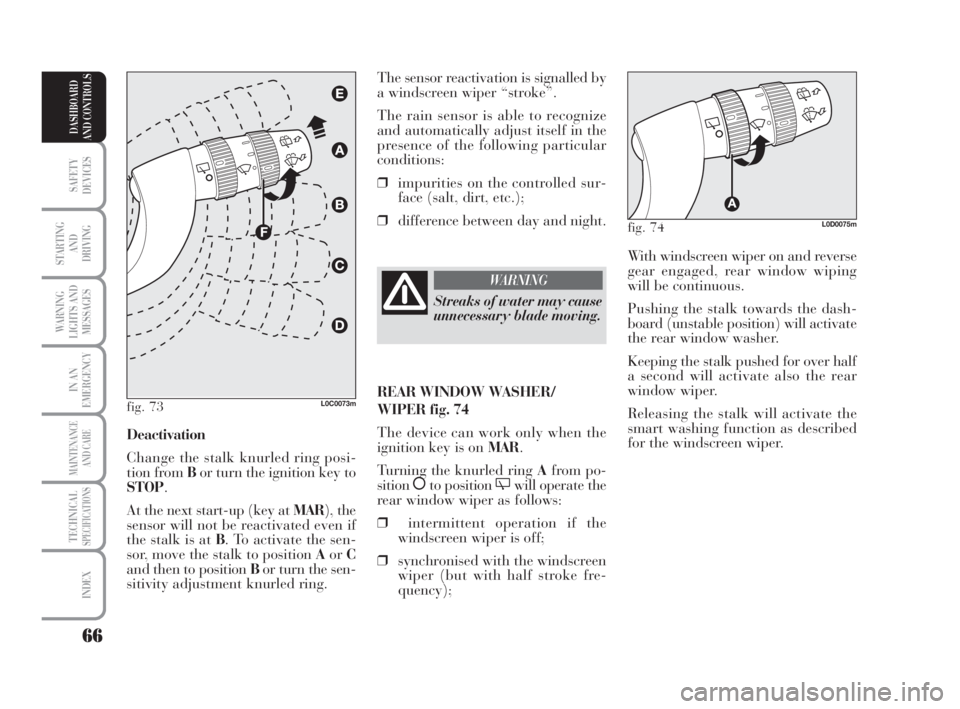
Turn the knurled ring F-fig. 73to in-
crease the rain sensor sensitivity.
The increase of the sensitivity of the
rain sensor is signalled by a control
and acquisition “stroke”.
By operating the windscreen washer
with the rain sensor enabled, a smart
washing cycle is carried out, without
the additional stroke after 5 seconds;
once completed, the sensor resumes its
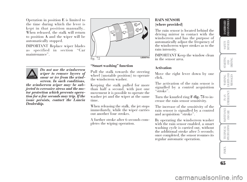
regular automatic operation. “Smart washing” function
Pull the stalk towards the steering
wheel (unstable position) to operate
the windscreen washer.
Keeping the stalk pulled for more
than half a second, with just one
movement it is possible to operate the
washer jet and the wiper at the same
time.
When releasing the stalk, the jet stops
immediately, while the wiper carries
out another four strokes.
A further stroke after 6 seconds com-
pletes the wiping operation. Do not use the windscreen
wiper to remove layers of
snow or ice from the wind-
screen. In such conditions,
the windscreen wiper may be sub-
jected to excessive stress and the mo-
tor protection which prevents opera-
tion for a few seconds may trip. If the
issue persists, contact the Lancia
Dealership.
fig. 72L0D0074m
038-094 MUSA 1ed GB 11-07-2008 14:10 Pagina 65
Page 67 of 218
66
SAFETY
DEVICES
STARTING
AND
DRIVING
WARNING
LIGHTS AND
MESSAGES
IN AN
EMERGENCY
MAINTENANCE
AND CARE
TECHNICALSPECIFICATIONS
INDEX
DASHBOARD
AND CONTROLS
With windscreen wiper on and reverse
gear engaged, rear window wiping
will be continuous.
Pushing the stalk towards the dash-
board (unstable position) will activate
the rear window washer.
Keeping the stalk pushed for over half
a second will activate also the rear
window wiper.
Releasing the stalk will activate the
smart washing function as described
for the windscreen wiper. The sensor reactivation is signalled by
a windscreen wiper “stroke”.
The rain sensor is able to recognize
and automatically adjust itself in the
presence of the following particular
conditions:
❒impurities on the controlled sur-
face (salt, dirt, etc.);
❒difference between day and night.
Deactivation
Change the stalk knurled ring posi-
tion from Bor turn the ignition key to
STOP.
At the next start-up (key at MAR), the
sensor will not be reactivated even if
the stalk is at B. To activate the sen-
sor, move the stalk to position AorC
and then to position Bor turn the sen-
sitivity adjustment knurled ring.
fig. 73L0C0073m
Streaks of water may cause
unnecessary blade moving.
WARNING
REAR WINDOW WASHER/
WIPER fig. 74
The device can work only when the
ignition key is on MAR.
Turning the knurled ring Afrom po-
sition
åto position 'will operate the
rear window wiper as follows:
❒intermittent operation if the
windscreen wiper is off;
❒synchronised with the windscreen
wiper (but with half stroke fre-
quency);
fig. 74L0D0075m
038-094 MUSA 1ed GB 11-07-2008 14:10 Pagina 66
Page 91 of 218
90
SAFETY
DEVICES
STARTING
AND
DRIVING
WARNING
LIGHTS AND
MESSAGES
IN AN
EMERGENCY
MAINTENANCE
AND CARE
TECHNICALSPECIFICATIONS
INDEX
DASHBOARD
AND CONTROLS
IMPORTANT When making ma-
noeuvres requiring maximum steering
efforts, the steering wheel may be-
come hard to turn; this is normal and
is due to the intervention of the steer-
ing control electric motor overheating
protection system. No repairs are,
therefore, required. The power steer-
ing system will return to normal op-
eration the next time the car is used.PARKING SENSORS
(where provided)
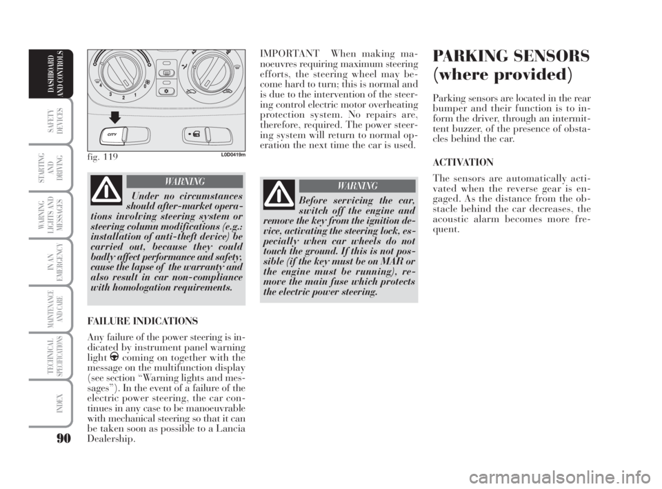
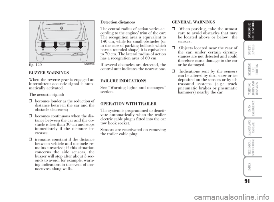
Parking sensors are located in the rear
bumper and their function is to in-
form the driver, through an intermit-
tent buzzer, of the presence of obsta-
cles behind the car.
ACTIVATION
The sensors are automatically acti-
vated when the reverse gear is en-
gaged. As the distance from the ob-
stacle behind the car decreases, the
acoustic alarm becomes more fre-
quent.
fig. 119L0D0419m
Under no circumstances
should after-market opera-
tions involving steering system or
steering column modifications (e.g.:
installation of anti-theft device) be
carried out, because they could
badly affect performance and safety,
cause the lapse of the warranty and
also result in car non-compliance
with homologation requirements.
WARNING
FAILURE INDICATIONS
Any failure of the power steering is in-
dicated by instrument panel warning
light
gcoming on together with the
message on the multifunction display
(see section “Warning lights and mes-
sages”). In the event of a failure of the
electric power steering, the car con-
tinues in any case to be manoeuvrable
with mechanical steering so that it can
be taken soon as possible to a Lancia
Dealership.
Before servicing the car,
switch off the engine and
remove the key from the ignition de-
vice, activating the steering lock, es-
pecially when car wheels do not
touch the ground. If this is not pos-
sible (if the key must be on MAR or
the engine must be running), re-
move the main fuse which protects
the electric power steering.
WARNING
038-094 MUSA 1ed GB 11-07-2008 14:11 Pagina 90
Page 92 of 218
91
SAFETY
DEVICES
STARTING
AND
DRIVING
WARNING
LIGHTS AND
MESSAGES
IN AN
EMERGENCY
MAINTENANCE
AND CARE
TECHNICALSPECIFICATIONS
INDEX
DASHBOARD
AND CONTROLS
Detection distances
The central radius of action varies ac-
cording to the engine/ trim of the car:
The recognition area is equivalent to
140 cm, while for small obstacles (or
in the case of parking bollards which
have a rounded shape) it is equivalent
to 70 cm. The lateral radius of action
has a recognition area of 60 cm.
If several obstacles are detected, the
control unit indicates the nearest one.
FAILURE INDICATIONS
See “Warning lights and messages”
section.
OPERATION WITH TRAILER
The system is programmed to deacti-
vate automatically when the trailer
electric cable plug is fitted into the car
tow hook socket.
Sensors are reactivated on removing
the trailer cable plug. BUZZER WARNINGS
When the reverse gear is engaged an
intermittent acoustic signal is auto-
matically activated.
The acoustic signal:
❒becomes louder as the reduction of
distance between the car and the
obstacle decreases;
❒becomes continuous when the dis-
tance between the car and the ob-
stacle is less than 30 cm and stops
immediately if the distance in-
creases;
❒iremains constant if the distance
between vehicle and obstacle re-
mains unvaried; if this situation
concerns the side sensors, the
buzzer will stop after about 3 sec-
onds to avoid, for example, warn-
ing indications in the event of ma-
noeuvres along walls.
fig. 120L0D0395m
GENERAL WARNINGS
❒When parking, take the utmost
care to avoid obstacles that may
be located above or below the
sensors.
❒Objects located near the rear of
the car, under certain circum-
stances are not detected and could
therefore cause damage to the car
or be damaged.
❒Indications sent by the sensors
can be altered by dirt, snow or ice
deposited on the sensors or by ul-
trasound systems (e.g.: truck
pneumatic brakes or pneumatic
hammers) nearby the car.
038-094 MUSA 1ed GB 11-07-2008 14:11 Pagina 91