Side rear light Lancia Musa 2010 Owner handbook (in English)
[x] Cancel search | Manufacturer: LANCIA, Model Year: 2010, Model line: Musa, Model: Lancia Musa 2010Pages: 218, PDF Size: 3.71 MB
Page 14 of 218
13
SAFETY
STARTING
AND DRIVING
WARNING
LIGHTS AND
MESSAGES
IN AN
EMERGENCY
MAINTENANCE
AND CARE
TECHNICAL
SPECIFICA-
TIONS
INDEX
DASHBOARD
AND
CONTROLS
KEY KIT AND
DOOR LOCKING
SYSTEM
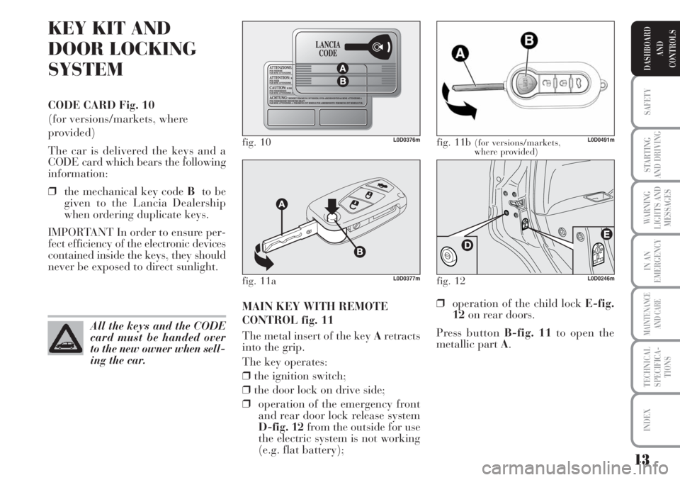
CODE CARD Fig. 10
(for versions/markets, where
provided)
The car is delivered the keys and a
CODE card which bears the following
information:
❒the mechanical key code Bto be
given to the Lancia Dealership
when ordering duplicate keys.
IMPORTANT In order to ensure per-
fect efficiency of the electronic devices
contained inside the keys, they should
never be exposed to direct sunlight.
MAIN KEY WITH REMOTE
CONTROL fig. 11
The metal insert of the key Aretracts
into the grip.
The key operates:
❒the ignition switch;
❒the door lock on drive side;
❒operation of the emergency front
and rear door lock release system
D-fig. 12from the outside for use
the electric system is not working
(e.g. flat battery);
fig. 10L0D0376m
All the keys and the CODE
card must be handed over
to the new owner when sell-
ing the car.
fig. 11b (for versions/markets,
where provided)L0D0491m
❒operation of the child lock E-fig.
12on rear doors.
Press button B-fig. 11to open the
metallic part A.
fig. 12L0D0246mfig. 11aL0D0377m
Page 17 of 218
16
SAFETY
STARTING
AND DRIVING
WARNING
LIGHTS AND
MESSAGES
IN AN
EMERGENCY
MAINTENANCE
AND CARE
TECHNICAL
SPECIFICA-
TIONS
INDEX
DASHBOARD
AND
CONTROLS
Request for additional remote
controls
The system may recognise up to 8 re-
mote controls. Should a new remote
control be necessary, contact a Lancia
Dealership, taking with you the
CODE card, a personal identity doc-
ument and the car’s ownership docu-
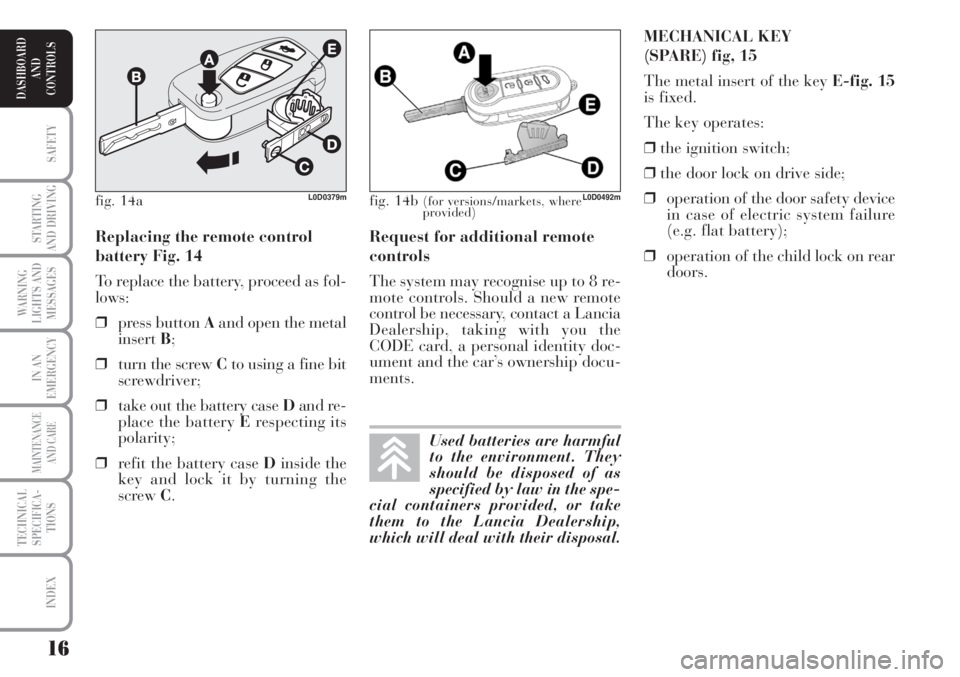
ments.MECHANICAL KEY
(SPARE) fig, 15
The metal insert of the key E-fig. 15
is fixed.
The key operates:
❒the ignition switch;
❒the door lock on drive side;
❒operation of the door safety device
in case of electric system failure
(e.g. flat battery);
❒operation of the child lock on rear
doors. Replacing the remote control
battery Fig. 14
To replace the battery, proceed as fol-
lows:
❒press button Aand open the metal
insertB;
❒turn the screw Cto using a fine bit
screwdriver;
❒take out the battery case Dand re-
place the battery Erespecting its
polarity;
❒refit the battery case Dinside the
key and lock it by turning the
screw C.
fig. 14b (for versions/markets, where
provided)L0D0492m
Used batteries are harmful
to the environment. They
should be disposed of as
specified by law in the spe-
cial containers provided, or take
them to the Lancia Dealership,
which will deal with their disposal.
fig. 14aL0D0379m
Page 20 of 218
19
SAFETY
STARTING
AND DRIVING
WARNING
LIGHTS AND
MESSAGES
IN AN
EMERGENCY
MAINTENANCE
AND CARE
TECHNICAL
SPECIFICA-
TIONS
INDEX
DASHBOARD
AND
CONTROLS
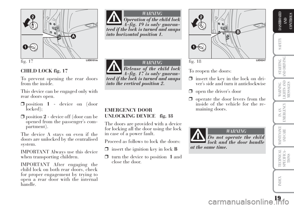
CHILD LOCK fig. 17
To prevent opening the rear doors
from the inside.
This device can be engaged only with
rear doors open.
❒position1- device on (door
locked);
❒position2- device off (door can be
opened from the passenger’s com-
partment).
The device A stays on even if the
doors are unlocked by the centralised
system.
IMPORTANT Always use this device
when transporting children.
IMPORTANT After engaging the
child lock on both rear doors, check
for proper engagement by trying to
open a rear door with the internal
handle.To reopen the doors:
❒insert the key in the lock on dri-
ver’s side and turn it anticlockwise
❒open the driver’s door
❒operate the door levers from the
inside of the vehicle for the re-
maining doors.
fig. 17L0D0101m
Operation of the child lock
A-fig. 19 is only guaran-
teed if the lock is turned and snaps
into horizontal position 1.
WARNING
Release of the child lock
A-fig. 17 is only guaran-
teed if the lock is turned and snaps
into the vertical position 2.
WARNING
EMERGENCY DOOR
UNLOCKING DEVICE fig. 18
The doors are provided with a device
for locking all the door using the lock
in case of a power fault.
Proceed as follows to lock the doors:
❒insert the ignition key in lock B
❒turn the device to position 1and
close the door.
fig. 18L0D0247
Do not operate the child
lock and the door handle
at the same time.
WARNING
Page 31 of 218
30
SAFETY
STARTING
AND DRIVING
WARNING
LIGHTS AND
MESSAGES
IN AN
EMERGENCY
MAINTENANCE
AND CARE
TECHNICAL
SPECIFICA-
TIONS
INDEX
DASHBOARD
AND
CONTROLS
Unlocking the doors and the
tailgate (key)
This function is used to: unlock the
front and rear doors, unlock the dri-
ver’s side door or all the doors includ-
ing the tailgate.
Proceed as follows to set:
– briefly press button MODE: “Open
doors”, “Open driver”, “Open all”;
– press button +or–to select. The se-
lected item will blink.
– briefly press button MODEto go
back to the menu screen or hold the
button pressed to go back to the stan-
dard screen without storing the set-
tings. – briefly press MODE: “month” will
start flashing on the display;
– press button +or–to set;
– briefly press button MODE: “day”
will start flashing on the display;
– press button +or–to set.
Note The setting will increase or de-
crease by one unit each time +or–is
pressed. Hold the button pressed to in-
crease/decrease the setting rapidly.
Complete the setting by briefly press-
ing the button when you approach the
required setting.
– briefly press button MODEto go
back to the menu screen or hold the
button pressed to go back to the stan-
dard screen without storing the set-
tings. 12h/24h clock mode
This function is used to select 12h or
24 h display.
To carry out the adjustment, proceed
as follows:
–briefly pressMODE: either 12h or
24h will start flashing on the display
(according to the previous setting);
– press button +or–for setting;
– briefly press button MODEto go
back to the menu screen or hold the
button pressed to go back to the stan-
dard screen without storing the set-
tings.
Set date
This function is used to set the date
(year – month – day).
Proceed as follows to update:
– briefly press button MODE: “year”
will start flashing on the display;
– press +or–to adjust;
Page 41 of 218
40
SAFETY
STARTING
AND DRIVING
WARNING
LIGHTS AND
MESSAGES
IN AN
EMERGENCY
MAINTENANCE
AND CARE
TECHNICAL
SPECIFICA-
TIONS
INDEX
DASHBOARD
AND
CONTROLS
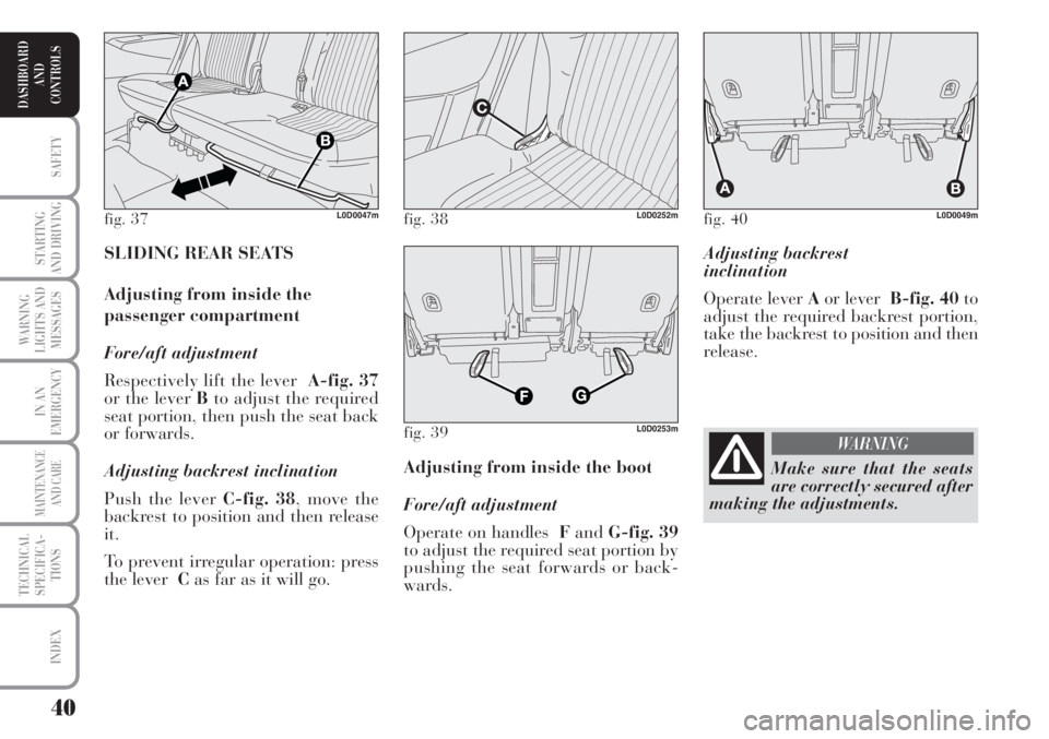
Adjusting backrest
inclination
Operate lever Aor leverB-fig. 40to
adjust the required backrest portion,
take the backrest to position and then
release.
Adjusting from inside the boot
Fore/aft adjustment
Operate on handles FandG-fig. 39
to adjust the required seat portion by
pushing the seat forwards or back-
wards. SLIDING REAR SEATS
Adjusting from inside the
passenger compartment
Fore/aft adjustment
Respectively lift the lever A-fig. 37
or the lever Bto adjust the required
seat portion, then push the seat back
or forwards.
Adjusting backrest inclination
Push the lever C-fig. 38, move the
backrest to position and then release
it.
To prevent irregular operation: press
the lever Cas far as it will go.
fig. 37L0D0047mfig. 38L0D0252m
fig. 39L0D0253m
fig. 40L0D0049m
Make sure that the seats
are correctly secured after
making the adjustments.
WARNING
Page 43 of 218
42
SAFETY
STARTING
AND DRIVING
WARNING
LIGHTS AND
MESSAGES
IN AN
EMERGENCY
MAINTENANCE
AND CARE
TECHNICAL
SPECIFICA-
TIONS
INDEX
DASHBOARD
AND
CONTROLS
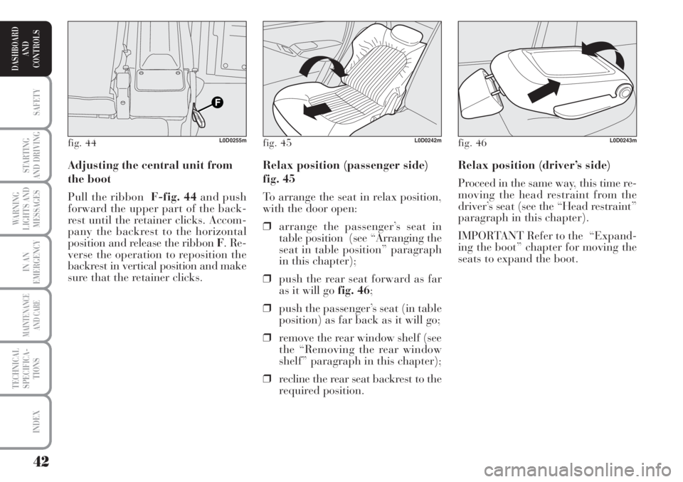
Relax position (driver’s side)
Proceed in the same way, this time re-
moving the head restraint from the
driver’s seat (see the “Head restraint”
paragraph in this chapter).
IMPORTANT Refer to the “Expand-
ing the boot” chapter for moving the
seats to expand the boot. Relax position (passenger side)
fig. 45
To arrange the seat in relax position,
with the door open:
❒arrange the passenger’s seat in
table position (see “Arranging the
seat in table position” paragraph
in this chapter);
❒push the rear seat forward as far
as it will go fig. 46;
❒push the passenger’s seat (in table
position) as far back as it will go;
❒remove the rear window shelf (see
the “Removing the rear window
shelf” paragraph in this chapter);
❒recline the rear seat backrest to the
required position. Adjusting the central unit from
the boot
Pull the ribbonF-fig. 44and push
forward the upper part of the back-
rest until the retainer clicks. Accom-
pany the backrest to the horizontal
position and release the ribbon F. Re-
verse the operation to reposition the
backrest in vertical position and make
sure that the retainer clicks.
fig. 44L0D0255mfig. 45L0D0242mfig. 46L0D0243m
Page 45 of 218
44
SAFETY
STARTING
AND DRIVING
WARNING
LIGHTS AND
MESSAGES
IN AN
EMERGENCY
MAINTENANCE
AND CARE
TECHNICAL
SPECIFICA-
TIONS
INDEX
DASHBOARD
AND
CONTROLS
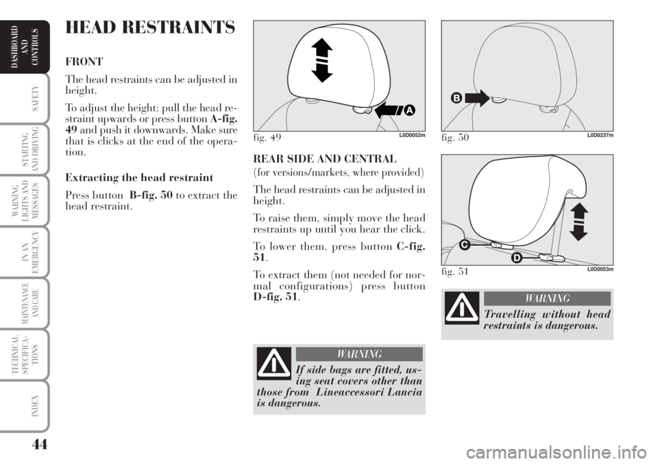
REAR SIDE AND CENTRAL
(for versions/markets, where provided)
The head restraints can be adjusted in
height.
To raise them, simply move the head
restraints up until you hear the click.
To lower them, press button C-fig.
51.
To extract them (not needed for nor-
mal configurations) press button
D-fig. 51.
HEAD RESTRAINTS
FRONT
The head restraints can be adjusted in
height.
To adjust the height: pull the head re-
straint upwards or press button A-fig.
49and push it downwards. Make sure
that is clicks at the end of the opera-
tion.
Extracting the head restraint
Press button B-fig. 50to extract the
head restraint.
fig. 49L0D0052mfig. 50L0D0237m
If side bags are fitted, us-
ing seat covers other than
those from Lineaccessori Lancia
is dangerous.
WARNING
fig. 51L0D0053m
Travelling without head
restraints is dangerous.
WARNING
Page 48 of 218
47
SAFETY
STARTING
AND DRIVING
WARNING
LIGHTS AND
MESSAGES
IN AN
EMERGENCY
MAINTENANCE
AND CARE
TECHNICAL
SPECIFICA-
TIONS
INDEX
DASHBOARD
AND
CONTROLS
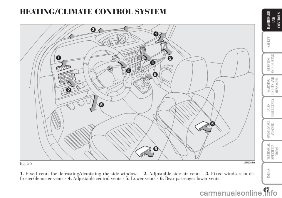
HEATING/CLIMATE CONTROL SYSTEM
fig. 56
1.Fixed vents for defrosting/demisting the side windows - 2.Adjustable side air vents - 3.Fixed windscreen de-
froster/demister vents - 4.Adjustable central vents - 5.Lower vents - 6.Rear passenger lower vents.
L0D0383m
Page 49 of 218
48
SAFETY
STARTING
AND DRIVING
WARNING
LIGHTS AND
MESSAGES
IN AN
EMERGENCY
MAINTENANCE
AND CARE
TECHNICAL
SPECIFICA-
TIONS
INDEX
DASHBOARD
AND
CONTROLS
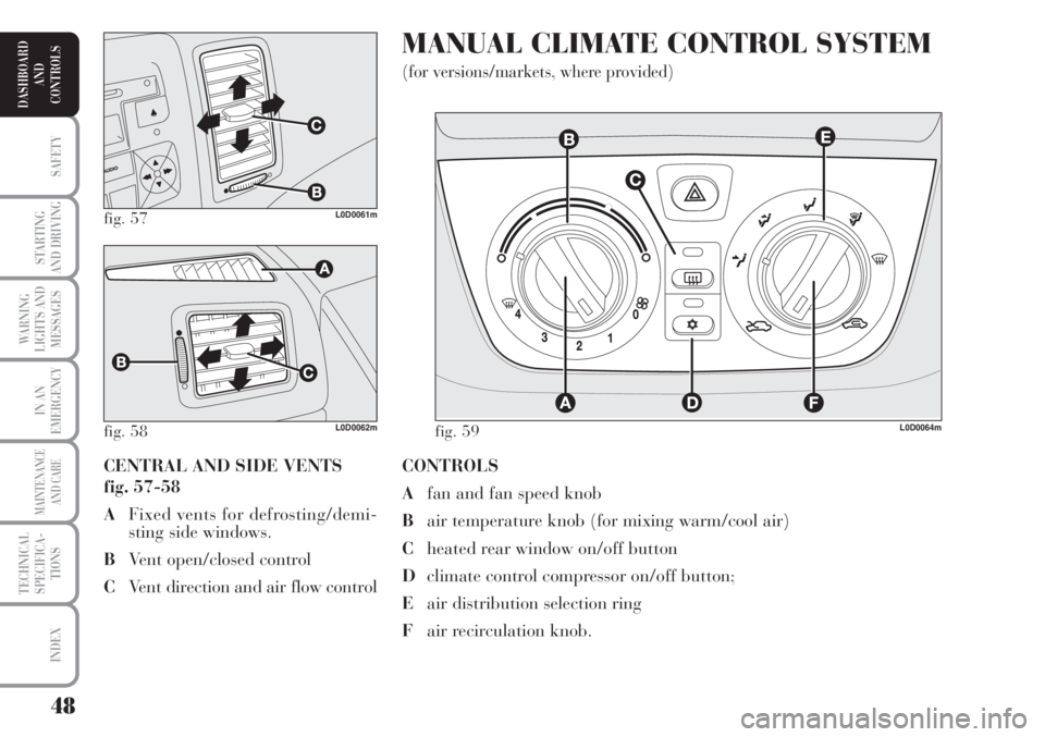
CONTROLS
Afan and fan speed knob
Bair temperature knob (for mixing warm/cool air)
Cheated rear window on/off button
Dclimate control compressor on/off button;
Eair distribution selection ring
Fair recirculation knob.
MANUAL CLIMATE CONTROL SYSTEM
(for versions/markets, where provided)
CENTRAL AND SIDE VENTS
fig. 57-58
AFixed vents for defrosting/demi-
sting side windows.
BVent open/closed control
CVent direction and air flow control
fig. 57L0D0061m
fig. 58 fig. 59L0D0062mL0D0064m
Page 52 of 218
51
SAFETY
STARTING
AND DRIVING
WARNING
LIGHTS AND
MESSAGES
IN AN
EMERGENCY
MAINTENANCE
AND CARE
TECHNICAL
SPECIFICA-
TIONS
INDEX
DASHBOARD
AND
CONTROLS
HEATED REAR WINDOW AND
DOOR MIRROR
DEMISTING/DEFROSTING
(for versions/markets, where provided)
Press button C-fig. 59to activate the
function. The LED in the button will
light up when the function is on.
The function is timed and automati-
cally deactivated by the system after
a given time. Press Cagain to switch
it off before.
IMPORTANT Do not apply stickers
on the inside of the rear window over
the heating filaments to avoid dam-
age that might cause it to stop work-
ing properly.Cooling
Proceed as follows:
❒stop internal air recirculation by
turning knob F-fig. 59to
Ú.
❒turn ring Bclockwise to increase
the temperature;
❒turn knob Aanticlockwise to re-
duce the fan speed.
LOOKING AFTER THE SYSTEM
Run the climate control system for at
least 10 minutes every month during
the winter. Have the system inspected
at a Lancia Dealership before the
summer. AIR CONDITIONING
(cooling and dehumidifying)
Proceed as follows:
❒turn the ring B-fig. 59to the blue
sector to select the temperature;
❒turn knob Ato the required speed;
❒turn the ring Eto
«;
❒turn the knob Fto
….
❒press button D
√(the LED on the
button will light up).